Advertisement
Quick Links
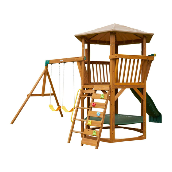
JUNGLE JOURNEY
PLAYSET
OBSTACLE FREE SAFETY ZONE - 318 5/8" x 306 1/2" (8.09m x 7.79m) area requires Protective Surfacing. See page 4.
MAXIMUM VERTICAL FALL HEIGHT - 6'4"(1.93m).
CAPACITY - 9 Users Maximum, Ages 3 to 10; Weight Limit 110 lbs. (50 kg) per child.
RESIDENTAL HOME USE ONLY. Not intended for public areas such as multi-unit residences, schools, churches, nurseries,
day cares or parks.
INSTALLATION AND OPERATING INSTRUCTIONS
FOR 24/7 ONLINE PARTS REPLACEMENT
parts.kidkraft.com
KidKraft, Inc.
4630 Olin Road
Dallas, Texas 75244
USA
customerservice@kidkraft.com
1.800.933.0771
972.385.0100
parts.kidkraft.eu
KidKraft Netherlands BV
Olympisch Stadion 8
1076 DE Amsterdam
The Netherlands
europecustomerservice@kidkraft.com
+31 20 305 8620
M-F from 09:00 to 17:30 (GMT+1)
306 1/2"
162.99"
7785
4140
9409355
Rev 07/25/2022
TWO-PERSON
ASSEMBLY TIME
ASSEMBLY
10 - 14 HOURS
WARNING
To reduce the risk of serious injury or death, please read and follow
these instructions. Keep and refer to instructions as needed and
pass along to any future owners of this item.
172.96"
4393.1
318 5/8"
8093.5
115.72"
2939.2
WARNING. ONLY
FOR OUTDOOR
DOMESTIC USE
Advertisement

Subscribe to Our Youtube Channel
Related Manuals for KidKraft JUNGLE


Summary of Contents for KidKraft JUNGLE
- Page 1 JUNGLE JOURNEY PLAYSET OBSTACLE FREE SAFETY ZONE - 318 5/8″ x 306 1/2″ (8.09m x 7.79m) area requires Protective Surfacing. See page 4. MAXIMUM VERTICAL FALL HEIGHT - 6’4”(1.93m). CAPACITY - 9 Users Maximum, Ages 3 to 10; Weight Limit 110 lbs. (50 kg) per child.
- Page 2 Congratulations on purchasing a KidKraft product! Our items are made of high-quality, durable Cunninghamia Lanceolata wood from the cypress family. Lumber from these trees are known for their light weight and excellent strength. The porosity of this wood allows the moisture to absorb and evaporate in the fibers, resisting rot and bugs.
-
Page 3: Warnings And Safe Play Instructions
Warnings and Safe Play Instructions CONTINUOUS ADULT SUPERVISION REQUIRED. Most serious injuries and deaths on playground equipment have occurred while children were unsupervised! Our products are designed to meet mandatory and voluntary safety standards. Complying with all warnings and recommendations in these instructions will reduce the risk of serious or fatal injury to children using this play system. - Page 4 Protective Surfacing - Reducing Risk of Serious Head Injury From Falls One of the most important things you can do to reduce the likelihood of serious head injuries is to install shock-absorbing protective surfacing under and around your play equipment. The protective surfacing should be applied to a depth that is suitable for the equipment height in accordance with ASTM F1292.
-
Page 5: Instructions For Proper Maintenance
Instructions for Proper Maintenance Your KidKraft Play System is designed and constructed of quality materials with your child’s safety in mind. As with all outdoor products used by children, it will weather and wear. To maximize the enjoyment, safety and life of your Play Set, it is important that you, the owner, properly maintain it. - Page 6 About Our Wood KidKraft Premium Play Systems uses only premium playset lumber, ensuring the safest product for your children’s use. Although we take great care in selecting the best quality lumber available, wood is still a product of nature and susceptible to weathering which can change the appearance of your set.
- Page 7 KidKraft Limited Warranty MISSING OR DAMAGED PARTS: KidKraft will replace any parts within 90 days from date of purchase found to be missing from or damaged in the original packaging. See Fig.1 Fig. 1 Product Age (All Parts) Consumer Pays...
-
Page 8: Keys To Assembly Success
Keys to Assembly Success Tools Required • Tape Measure • #1 Phillips, #2 Robertson • Open End Wrench • 3/16” Hex Key • Carpenters Level and Screwdriver (1/2” & 7/16”) • 8’ Step Ladder • Carpenters Square • Ratchet with extension •... - Page 9 Part Identification (Reduced Size) 1x - 10070 - 31.8 x 76.2 x 1564.2 mm - 37110070 1 1/4" X 3" X 61 9/16" 2x - 10071 - 31.8 x 76.2 x 1564.2 mm - 37110071 1 1/4" X 3" X 61 9/16" 4x - 10040 - 31.8 x 31.8 x 750 mm - 37110040 1 1/4"...
- Page 10 Part Identification (Reduced Size) 6x - 10050 - 939.8 x 76.2 x 31.8 mm - 37110050 1 1/4" X 3" X 37" 4x - 10051 - 31.8 x 76.2 x 263 mm - 37110051 1 1/4" X 3" X 10 3/8" 2x - 10053 - 31.8 x 76.2 x 976.5 mm - 37110053 1 1/4"...
- Page 11 Part Identification (Reduced Size) 12x - 10061 - 31.8 x 76.2 x 152.4 mm - 37110061 1 1/4" X 3" X 6" 6x - 10062 - 15.9 x 88.9 x 1118.8 mm - 37110062 5/8" X 3 1/2" X 44 1/16" 1x - 10063 - 15.9 x 76.2 x 865.1 mm - 37110063 5/8"...
- Page 12 Part Identification (Reduced Size) 1 3/8" x 2 1/2" x 57 53/64" 1x - 9054 - 34.9 x 63.5 x 1468.8mm - 3719054 1 3/8" x 2 1/2" x 57 53/64" 1x - 9055 - 34.9 x 63.5 x 1468.8mm - 3719055 1 3/8"...
- Page 13 Part Identification (Reduced Part Size) 1 1/4" x 23 3/8" x 71" 1 1/4" x 19" x 57 3/8" 1x - 9361 - 31.8 x 594 x 1803 mm - 37719361 2x - 9362 - 31.8 x 482 x 1458 mm - 37719362...
- Page 14 Part Identification (Reduced Part Size) If you need to order parts, 1x - SW Wall 9363 1x - - SW Wall please order below part # 2 9/16" x 38 1/4" x 92" 2 9/16" x 38 1/4" x 92" 65.7 x 971.2 x 2336.8mm 65.7 x 971.2 x 2336.8mm - 37719363 37719355 - SW Wall Left - 1pc...
- Page 15 Part Identification (Reduced Part Size) 1x - Rock Wall 1x - 9364 - Rock Wall 2 9/16" x 38 1/4" x 92" 2 9/16" x 38 1/4" x 92" If you need to order parts, 65.7 x 971.2 x 2336.8mm 65.7 x 971.2 x 2336.8mm - 37719364 please order below part # 37719357 - Rock Wall Left - 1pc...
- Page 16 Part Identification (Reduced Part Size) If you need to order parts, 1x - Slide Wall 1x - 9365 - Slide Wall please order below part # 2 9/16" x 38 1/4" x 92" 2 9/16" x 38 1/4" x 92" 65.7 x 971.2 x 2336.8mm 65.7 x 971.2 x 2336.8mm - 37719365 37719359 - Slide Wall Left - 1pc...
- Page 17 Part Identification (Reduced Part Size) 1x - (5pk) 7x - (9290318) 1x - (9320374) 1x - (3320161) 1x - 9200143 4x - 9200106 1x - 9200144 2x - (9200149) 1x - (3200143) 1x - (3320122) 2x - (3724943) 1x - (3322809)
- Page 18 Hardware Identification (Actual Size) 110x FW2 - 5/16" (7.9mm) 5x FW0 - 3/16" (4.8mm) 5x LW1 - 1/4" (6.4mm) 72x LW2 - 5/16" (7.9mm) - 51103300 - 51103100 - 51303200 - 51303300 63x TN2 - 5/16" (7.9mm) 5x BN1 - 1/4" (6.4mm) 24x FW3 - #8 54503300 2x FW1 - 1/4"...
- Page 19 Hardware Identification (Actual Size) 5/16 x 2-1/8" 5/16 x 1-3/8" 31x WB2 - 4x WB9 - (7.9 x 53.9mm) - 53613324 (7.9 x 34.9mm) - 53613316 5/16 x 3" 8x WB7 - (7.9 x 76.2mm) - 53613330 5/16 x 2-5/8" 8x WB10 - (7.9 x 66.7mm) - 53613329 5/16 x 2"...
-
Page 20: Order Replacement Parts
Inventory Parts - Read This Before Starting Assembly STOP STOP STOP STOP Inventory should be completed before starting installation. KidKraft will not cover costs of any additional installation trip due to missing or damaged pieces. This is the time for you to inventory all your hardware, wood and accessories, referencing the parts identification sheets. - Page 21 Step 2 9363 9364 9365 Wood Parts 65.7 x 971.2 x 2336.8mm (2-9/16 x 38-1/4 x 92”) 9363 65.7 x 971.2 x 2336.8mm (2-9/16 x 38-1/4 x 92”) 9364 65.7 x 971.2 x 2336.8mm (2-9/16 x 38-1/4 x 92”) 9365...
-
Page 22: Top View
Step 3 Flush 9365 9363 Flush 9364 Flush Top View Flush 9363 9365 9364 Rock Wall Side (BACK) Hardware 42 x #8 x 63.5 mm (#8 x 2-1/2”) - Page 23 Step 4 Note: Install T-Nut first! 10040 WB10 10040 WB10 WB10 10040 WB10 WB10 WB10 10040 Rock Wall Side (Back) 10040 5/8” (15.9mm) 10040 WB10 WB10 Wood Parts Hardware 31.8 x 31.8 x 750 mm (1-1/4 x 1-1/4 x 29”) 7.9mm x 66.6 mm (5/16 x 2-5/8”)(FW2, LW2, TN2) WB10 10040...
- Page 24 Step 5 Note: Install T-Nut first! 10071 10071 10071 Top View 10071 10071 Wood Parts Hardware Hardware 7.9mm x 76.2mm (5/16 x 3”) (FW2, LW2, TN2) 31.8 x 76.2 x 1564.2 mm (1-1/4 x 3 x 61-9/16”) 10071...
- Page 25 Step 6 10070 5/8” (15.9mm) 10070 10070 Wood Parts Hardware 31.8 x 76.2 x 1564.2 mm (1-1/4 x 3 x 61-9/16”) #8 x 76.2mm (#8 x 3”) 10070...
- Page 26 Step 7 9054 9058 10063 Flush Flush 9058 10063 Flush Wood Parts Hardware 34.9 x 63.5 x 1468.8 mm (1-3/8 x 2-1/2 x 57-53/64”) #8 x 35mm (#8 x 1-3/8”) 9054 34.9 x 63.5 x 1468.8 mm (1-3/8 x 2-1/2 x 57-53/64”) 9058 31.8 x 939.8 x 2336.8 mm (5/8 x 3 x 34-1/16”) 10063...
- Page 27 Step 8 9055 10067 10067 10067 9055 Flush Flush Flush Wood Parts Hardware 34.9 x 63.5 x 1468.8 mm (1-3/8 x 2-1/2 x 57-53/64”) #8 x 35mm (#8 x 1-3/8”) 9055 15.9 x 82.6 x 450mm (5/8 x 3-1/4 x 17-11/16”) 10067...
- Page 28 Step 9 10064 10064 10064 10064 10064 Hardware Wood Parts 16 x #8 x 64mm (#8 x 2-1/2”) 23.8 x 82.6 x 417.2 mm (15/16 x 3-1/4 x 16-7/16”) 10064...
- Page 29 Step 10 IMPORTANT! Follow hole pattern Pre-drill holes using a 1/8” drill bit. 10066 10066 10066 10066 10066 10065 10066 10066 Hardware Wood Parts 15.9 x 133.4 x 444.8 mm (5/8 x 5-1/4 x 17-1/2”) 24 x #12 x 50.8mm (#12 x 2”) 10065 15.9 x 133.4 x 444.8 mm (5/8 x 5-1/4 x 17-1/2”) 10066...
- Page 30 Step 11 Note: Make sure all hardware is used to properly secure each rock. choose the image you like best, they are the same 3320267 Hardware Other Parts 7.9mm x 32 mm (5/16 x 1-1/4”) (FW0, LW1, BN1) 3320267 (5pk) #8 x 25.4 mm (#8 x 1”)
- Page 31 Step 12 9365 9364 9363 9363 Rock Wall Side (BACK) 9364 Hardware #8 x 35mm (#8 x 1-3/8”)
- Page 32 Step 13 Pre-drill holes using a 1/8” drill bit. 10065 Wood Parts Hardware 15.9 x 133.4 x 444.8 mm (5/8 x 5-1/4 x 17-1/2”) #12 x 50.8mm (#12 x 2”) 10065 #8 x 44.5mm (#8 x 1-3/4”)
- Page 33 Step 14 9200222 Pre-drill each hole using a 1/8” drill bit. 9200222 Hardware Other Parts 6.4 x 35 mm (1/4 x 1-3/8”) (FW1) 9200222...
- Page 34 Step 15 Note: Align all floor panels before securing with 9362 hardware. 9361 9362 Top half of structure removed for clarity. x 53 9362 9362 9361 9362 Hardware Wood Parts 53 x #8 x 38.1mm (#8 x 1-1/2”) 31.8 x 482.6 x 1458 mm (1-1/4 x 19 x 57-3/8”) 9362 31.8 x 594 x 18030 mm (1-1/4 x 23-3/8 x 71”) 9361...
- Page 35 Step 16 x 5 Note: Install T-nuts first! 10048 10050 10049 10050 10050 10049 10048 Wood Parts Hardware Hardware 10 x 7.9mm x 34.9mm (5/16 x 1-3/8”) (FW2, LW2, TN2) 31.8 x 49 x 406.4 mm (1-1/4 x 1-15/16 x 16”) 10048 31.8 x 85.7 x 406.4 mm (1-1/4 x 3-3/8 x 16”) 10049...
- Page 36 Step 17 Note: Install T-nuts first! 10050 10048 10047 10050 10050 10047 10048 Wood Parts Hardware 7.9mm x 34.9mm (5/16 x 1-3/8”) (FW2, LW2, TN2) 31.8 x 85.7 x 406.4 mm (1-1/4 x 3-3/8 x 16”) 10047 31.8 x 50.8 x 406.4 mm (1-1/4 x 2 x 16”) 10048 31.8 x 76.2 x 939.8 mm (1-1/4 x 3 x 37”) 10050...
- Page 37 Step 18 Note: Install T-Nuts first! 10047 10049 10047 SW Wall Hardware 7.9mm x 34.9mm (5/16 x 1-3/8”) (FW2, LW2, TN2) #8 x 64mm (#8 x 2-1/2”)
- Page 38 Step 19 Note: Install T-Nuts first! 10049 Hardware 7.9mm x 34.9mm (5/16 x 1-3/8”) (FW2, LW2, TN2) #8 x 64mm (#8 x 2-1/2”)
- Page 39 Step 20 Note: Install T-Nuts first! 10049 Hardware 7.9mm x 34.9mm (5/16 x 1-3/8”) (FW2, LW2, TN2) #8 x 64mm (#8 x 2-1/2”)
- Page 40 Step 21 Hardware #8 x 64mm (#8 x 2-1/2”)
- Page 41 Step 22 Slide Wall Left 10046 10046 10046 10046 10046 10046 10046 Hardware Wood Parts 10 x 31.8 x 76.2 x 431.8 mm (1-1/4 x 3 x 17”) 20 x #8 x 64mm (#8 x 2-1/2”) 10046...
- Page 42 Step 23 10043 10043 10043 10043 10043 Hardware Wood Parts 31.8 x 76.2 x 139.7 mm (1-1/4 x 3 x 5-1/2”) 24 x #8 x 38.1mm (#8 x 1-1/2”) 10043...
- Page 43 Step 24 10055 10055 10055 Flush 10055 10055 Flush Hardware Wood Parts 31.8 x 63.5 x 800.0 mm (1-1/4 x 2-1/2 x 31-1/2”) 12 x #10 x 101.6mm (#10 x 4”) 10055...
- Page 44 Step 25 Note: Install T-Nuts first! 10068 10068 Wood Parts Hardware 7.9mm x 76.2mm (5/16 x 3”) (FW2, TN2) 76.2 x 85.0 x 406.4 mm (3 x 3-3/8 x 16”) 10068...
- Page 45 Step 26 10051 10051 10056 10056 Wood Parts Hardware 31.8 x 76.2 x 263.0 mm (1-1/4 x 3 x 10-3/8”) 7.9 x 54 mm (5/16 x 2-1/8”) (FW2, TN2) 10051 31.8 x 76.2 x 654.1 mm (1-1/4 x 3 x 25-3/4”) 10056...
- Page 46 Step 27 10056 10051 Flush Hardware 20 x #8 x 50.8 mm (#8 x 2”)
- Page 47 Step 28 x 4 10057 10045 Wood Parts Hardware 25.4 x 31.8 x 183.7 mm (1 x 1-1/4 x 7-1/4”) #8 x 50.8 mm (#8 x 2”) 10045 31.8 x 76.2 x 629.3 mm (1-1/4 x 3 x 24-3/4”) 10057...
- Page 48 Step 29 (Hidden) 10045 10045 Flush Bottom half of structure 10057 removed for clarity. 10057 Hardware 12 x #8 x 50.8 mm (#8 x 2”)
- Page 49 Step 30 (Hidden) 10054 10053 Note: Install T-Nuts first! 10054 10053 10053 10054 Wood Parts Hardware 31.8 x 76.2 x 976.5 mm (1-1/4 x 3 x 38-7/16”) 7.9 x 95 mm (5/16 x 3-3/4”) (FW2, LW2, TN2) 10053 31.8 x 76.2 x 976.5 mm (1-1/4 x 3 x 38-7/16”) #8 x 50.8 mm (#8 x 2”) 10054...
- Page 50 Step 31 Flush 10058 Evenly space 10058 10058 10058 10058 10058 10058 10058 10058 10058 10058 Wood Parts Hardware 24 x 31.8 x 31.8 x 699.1 mm (1-1/4 x 1-1/4 x 27-1/2”) 48 x #8 x 50.8 mm (#8 x 2”) 10058...
- Page 51 Step 32 10059 10059 10059 Flush 10059 10059 Bottom half of structure removed for clarity. 10059 Flush Hardware Wood Parts 24 x #8 x 38.1mm (#8 x 1-1/2”) 15.9 x 88.9 x 1026.8 mm (5/8 x 3-1/2 x 40-7/16”) 10059...
- Page 52 Step 33 Flush 10061 10061 10061 10061 10061 10061 10061 10061 10061 10061 10061 10061 10061 10061 Wood Parts Hardware 24 x #8 x 50.8 mm (#8 x 2”) 12 x 31.8 x 76.2 x 152.4 mm (1-1/4 x 3 x 6”) 10061...
- Page 53 Step 34 View from underneath 10062 10062 10062 10062 10062 Flush 10062 10062 Hardware Wood Parts 24 x #8 x 38.1mm (#8 x 1-1/2”) 15.9 x 88.9 x 1118.8 mm (5/8 x 3-1/2 x 44-1/16”) 10062...
- Page 54 Step 35 3320125 3320125 3320125 3320122 3320125 3320125 3320125 Other Parts 3320125 (6pk) 3320122...
- Page 55 Step 36 Top half of structure removed for clarity. 3320122 Hardware 12 x 7.9 x 50.8 mm (5/16 x 2”) (LW2, FW2, LN2)
- Page 56 Step 37 Note: Pre-drill all holes using a 1/8” drill bit before installing the S7 screws. Top half of structure removed for clarity. 3318115 3318115 Center Installation Hardware Other Parts #12 x 50.8mm (#12 x 2”) 3318115...
- Page 57 Step 38 Note: Install T-Nuts first! Note: Tighten nut after the following step. 10044 3203021 10044 3203021 3203021 3203021 10044 10044 3203021 3203021 10044 10044 3203021 3203021 3203021 10044 3203021 3203021 3203021 3203021 Other Parts Wood Parts Hardware Hardware (6pk) 7.9mm x 34.9mm (5/16 x 1-3/8”) (FW2, TN2) 31.8 x 76.2 x 139.7 mm (1-1/4 x 3 x 5-1/2”) 3203021...
- Page 58 Step 39 10044 Tighten LN2 at this step. Flush Flush Flush Flush Flush Flush Hardware 24 x #8 x 38.1mm (#8 x 1-1/2”)
- Page 59 Step 40 10042 10042 10042 10042 10042 10042 10042 10042 Bottom half of structure removed for clarity. Wood Parts Hardware 15.9 x 34.9 x 1137.2 mm (5/8 x 1-3/8 x 44-3/4”) 12 x #8 x 38.1mm (#8 x 1-1/2”) 10042...
- Page 60 Step 41 Note: Evenly distribute fabric roof. 3322809 Other Parts 3322809...
- Page 61 Step 42 3322809 (Hidden) (Hidden) View from underneath 3322809 3322809 Hardware 24 x #7 x 15.87mm (#7 x 5/8”) (FW3)
- Page 62 Step 43 View from underneath...
- Page 63 Step 44 (Hidden) 3320161 Top half of structure removed for clarity. Flush 3320161 Other Parts Hardware 3320161 #8 x 44.5mm (#8 x 1-3/4”)
- Page 64 Step 45 Notice Angle Orientation 9200106 10069 Wood Parts Hardware Other Parts 76.2 x 133.4 x 1854.2 mm (3” x 5-1/4” x 73”) 9200106 7.9mm x 139.7 mm (5/16 x 5-1/2”) (LN2, 2 x FW2) 10069...
- Page 65 Step 46 Center plaque on beam and between both swings. 10069 Notice Angle Orientation 3320355 Hardware Other Parts 1 x 3320355 #7 x 15.87mm (#7 x 5/8”)
- Page 66 Step 47 2613 2615 2613 Wood Parts Hardware 50.8 x 76.2 x 2201.9 mm (2 x 3 x 86-11/16”) 7.9 x 139.7 mm (5/16 x 5-1/2”) (LW2, FW2, TN2) 2613 76.2 x 76.2 x 1294.3 mm (3 x 3 x 50-15/16”) 2615...
- Page 67 Step 48 IT IS IMPORTANT THAT THESE BOLTS ARE ATTACHED. THEY WILL MINIMIZE CHECKING OF WOOD. 2616 2616 Wood Parts Hardware 23.8 x 82.6 x 1181.1mm (15/16 x 3-1/4 x 46-1/2”) 7.9mm x 101.6mm (5/16 x 4”) (LW2, FW2, TN2) 2616 7.9mm x 76.2mm (5/16 x 3”) (LW2, FW2, TN2)
- Page 68 Step 49 9200144 9200143 Hardware Other Parts 7.9 x 95 mm (5/16 x 3-3/4”) (2 x FW2, LW2, LN2) 9200143 9200144...
- Page 69 Step 50 10069 9200149 Hardware Hardware Other Parts 7.9 x 95 mm (5/16 x 3-3/4”) (2 x FW2, LW2, LN2) 9200149...
- Page 70 Step 51 3724943 Tighten Caution: Threaded Quick Links must Threaded Link be installed with the gate completely using adjustable down covering the threads and wrench tighten as instructed. Other Parts 3724943...
- Page 71 Step 52 9320374 Top half of structure removed for clarity. KidKraft I.D. Plaque 9320374 Hardware Other Parts #6 x 15.9 mm (#6 x 5/8”) 1 x 9320374...
- Page 72 Step 53 MOVE FORT TO FINAL LOCATION PRIOR TO STAKING FINAL LOCATION MUST BE LEVEL GROUND Warning! To prevent tipping and avoid potential injury, stakes must be driven 13”(330mm) into ground. Digging or driving stakes can 9290318 be dangerous if you do not 13”...
- Page 73 NOTES...
- Page 74 NOTES...
- Page 75 NOTES...
- Page 76 2) Complete the registration online at: https://www.kidkraft.com/us_en/warranty/ 3) Mail this completed form to: KidKraft Inc., 4630 Olin Road, Dallas, Tx 75244 USA Make sure to include a copy of your proof of purchase...
Need help?
Do you have a question about the JUNGLE and is the answer not in the manual?
Questions and answers