KidKraft COZY ESCAPE PLAYHOUSE F29045 Installation And Operating Instructions Manual
Hide thumbs
Also See for COZY ESCAPE PLAYHOUSE F29045:
Table of Contents
Advertisement
Quick Links
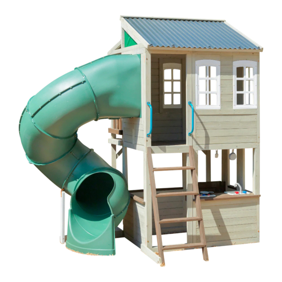
COZY ESCAPE PLAYHOUSE - F29045
INSTALLATION AND OPERATING INSTRUCTIONS
WARNING
OBSTACLE FREE SAFETY ZONE - 23' 7.5" x 20'1.7" (720 x 677 cm) area requires Protective Surfacing. See page 3.
MAXIMUM VERTICAL FALL HEIGHT - 56-5/16" (1.43m)
CAPACITY - 11 Users Maximum, Ages 3 to 10; Weight Limit 110 lbs.
(49.9 kg) per child.
RESIDENTIAL HOME USE ONLY. Not intended for public areas such as
multi-unit residences, schools, churches, nurseries, day cares or parks.
Warning. Only for domestic use.
720cm
23' 7.5"
320cm
10' 6"
2 - 4 Hrs
10 - 12 Hrs
10 - 12 Hrs
2-4 Hrs
1 - 2 Hrs
FOR FORT
FOR FORT & SWING
FOR FORT & SWING
TUBE SLIDE
TWO PERSON
TWO PERSON
ASSEMBLY
ASSEMBLY
KidKraft, Inc.
4630 Olin Road
Dallas, Texas 75244 USA
customerservice@kidkraft.com
canadacustomerservice@kidkraft.com
1.800.933.0771
972.385.0100
For online parts replacement visit
https://parts.kidkraft.com/
To reduce the risk of serious injury or death, you must read and follow these instructions. Keep and
refer to these instructions often and give them to any future owner of this play set. Manufacturer
contact information provided below.
277cm
677cm
7' 25"
20' 1.7"
For Outdoor Family
Domestic Use Only
KidKraft Netherlands BV
Olympisch Stadion 29
1076DE Amsterdam
The Netherlands
europecustomerservice@kidkraft.com
+31 20 305 8620 M-F from 09:00 to 17:30
(GMT+1)
For online parts replacement visit
https://parts.kidkraft.eu/
Table of Contents
Warnings And Safe Play Instructions . . . . . . . . . . pg . 2
Protective Surfacing Guidelines . . . . . . . . . . . . . . . pg . 3
Instructions For Proper Maintenance . . . . . . . . . pg . 4
About Our Wood – Limited Warranty . . . . . . . . . pg . 5
Keys To Assembly Success . . . . . . . . . . . . . . . . . . . . pg . 6
Part ID . . . . . . . . . . . . . . . . . . . . . . . . . . . . . . . . . . . pg . 8-19
Step-By-Step Instructions . . . . . . . . . . . . . . . . . . .pg . 20
Installation of I . D . / Warning Plaque . . . . . .Final Step
9409045
Rev 05/08/2019
Advertisement
Table of Contents

Related Manuals for KidKraft COZY ESCAPE PLAYHOUSE F29045


Summary of Contents for KidKraft COZY ESCAPE PLAYHOUSE F29045
- Page 1 Instructions for Proper Maintenance . . . . . . . . . pg . 4 About Our Wood – Limited Warranty . . . . . . . . . pg . 5 KidKraft, Inc. KidKraft Netherlands BV 4630 Olin Road Olympisch Stadion 29 Keys to Assembly Success .
- Page 2 Warnings and Safe Play Instructions CONTINUOUS ADULT SUPERVISION REQUIRED. Most serious injuries and deaths on playground equipment have occurred while children were unsupervised! Our products are designed to meet mandatory and voluntary safety standards. Complying with all warnings and recommendations in these instructions will reduce the risk of serious or fatal injury to children using this play system.
- Page 3 Protective Surfacing - Reducing Risk of Serious Head Injury From Falls. One of the most important things you can do to reduce the likelihood of serious head injuries is to install shock-absorbing protective surfacing under and around your play equipment. The protective surfacing should be applied to a depth that is suitable for the equipment height in accordance with ASTM F1292.
- Page 4 Instructions for Proper Maintenance Your KidKraft Play System is designed and constructed of quality materials with your child’s safety in mind. As with all outdoor products used by children, it will weather and wear. To maximize the enjoyment, safety and life of your Play Set, it is important that you, the owner, properly maintain it.
- Page 5 About Our Wood KidKraft Premium Play Systems uses only premium playset lumber, ensuring the safest product for your children’s use. Although we take great care in selecting the best quality lumber available, wood is still a product of nature and susceptible to weathering which can change the appearance of your set.
- Page 6 Keys to Assembly Success Tools Required • Tape Measure • #1, #2 & #3 Phillips • Open End Wrench • 3/16” Hex Key • Carpenters Level or Robertson Bits (7/16”, 1/2” & 9/16”) • 8’ Step Ladder • Carpenters Square or Screwdriver •...
- Page 7 Your Key To Quick Assembly Step Step Step SAVE TIME - TIP #1: Wood parts are found in Box 2, 3, 4 & 5. Open each box with wood parts and look for the Key Number stamped on the end of the wood part (see chart below). Sort each wood part into the different assembly steps.
- Page 8 Part Identification (Reduced Part Size) Part Identification (Reduced Part Size) Part Identification (Reduced Part Size) Part Identification (Reduced Part Size) 4pc. - 9460 - 31.8 x 63.5 x 1355.8 - Floor Joist - Box 1 - 3569460 1-1/4 x 2-1/2 x 53-3/8" 4pc.
- Page 9 Part Identification (Reduced Part Size) Part Identification (Reduced Part Size) Part Identification (Reduced Part Size) Part Identification (Reduced Part Size) 1pc. - 9478 - 34.9 x 69.9 x 1309.1 - Left Rail - Box 2 - 3589478 1-3/8 x 2-3/4 x 51-17/32" 1pc.
- Page 10 1pc. - 9497 - 31.8 x 63.5 x 534.9 - Crowsnest Short A - Box 1 - 3569497 1-1/4 x 2-1/2 x 21-1/16" 1pc. - 9498 - 31.8 x 63.5 x 566.7 - Crowsnest Short L - Box 1 - 3569498 1-1/4 x 2-1/2 x 22-5/16"...
- Page 11 Part Identification (Reduced Part Size) Part Identification (Reduced Part Size) Part Identification (Reduced Part Size) Part Identification (Reduced Part Size) 3pc. - 9515 - 25.4 x 63.5 x 866.8 - Table Top - Box 2 - 3589515 1 x 2-1/2 x 34-1/8" 2pc.
- Page 12 Part Identification (Reduced Part Size) 1pc. - 9265 - 63.5 x 866.6 x 2286mm 1pc. - 9264 - 63.5 x 558.8 x 2286mm 2-1/2 x 34-1/4 x 90" 2-1/2 x 22 x 90" Folding Panel Assembly Left B - Folding Panel Assembly Left A - 37569265 37569264 1pc.
- Page 13 Hardware Identification (Actual Size) 7pc. FW0 - 3/16" Flat Washer - (51103100) 4.8mm 9pc. TN1 - 1/4" T - Nut (54503200) 16pc. LW1 - 1/4" Lock Washer - (51303200) 6.4mm 6.4mm 19pc. FW1 - 1/4" Flat Washer - (51103200) 6.4mm 20pc.
- Page 14 Door Hinge (2 Pk) Robertson Driver (3200147) (9200014) 1x - TNR 3 Tube Support (9201601) 1x - TNR4 Post Mount Kit (3201655) 1x - Kidkraft 31x - Square 2x - TNR 4 Post Nylok Nut Mount Clamp (54902200) (9320374) (9201657)
- Page 15 Before you discard your cartons fill out the form below. • The carton I.D. stamp is located on the end of each carton. The tracking number is located on the KidKraft ID Plaque (9320374). • Please retain this information for future reference. You will need this information if you contact the Consumer Relations Department.
- Page 16 Step 2: Frame Assembly Part 1 A: With a helper, stand the (9263) Folding Panel Assembly Right A in the upright position and unfold, checking to make sure the panel assembly is square. Pre-drill using a 3/16” drill bit, then install 5 (WL5) 1/4 x 2- 1/2” Wafer Lags to secure the panel.
- Page 17 Step 2: Frame Assembly Part 2 C: With a helper, stand the (9264) Folding Panel Assembly Left A in the upright position and unfold, checking to make sure the panel assembly is square. Pre-drill using a 3/16” drill bit, then install 5 (WL5) 1/4 x 2- 1/2” Wafer Lags to secure the panel.
- Page 18 Step 3: Join Frame Assemblies Part 1 A: From inside the assembly, halfway up and tight to both end walls, place 1 (9462) Side Joist against (9265) Folding Panel Assembly Left B and (9264) Folding Panel Assembly Left A, making sure that it’s 5/8” below the panel opening.
- Page 19 Step 3: Join Frame Assemblies Part 2 C: Place 1 (9460) Floor Joist along the bottom of the front and back walls so they are flush to the bottom. Check to make sure that the joists are level then attach each joist using 4 (S7) #12 x 2” Pan Screws. (fig.3.4, 3.5 and 3.7) D: Place 1 (9461) Floor Joist Short along each end wall, between the (9460) Floor Joists.
- Page 20 Step 3: Join Frame Assemblies Part 3 E: Place 1 (9460) Floor Joist along the top of the front and back walls so they are flush to the top. Check to make sure that the joists are level then attach each joist using 5 (S7) #12 x 2” Pan Screws. (fig.3.9 and 3.10) F: Place 1 (9461) Floor Joist Short along the top of each end wall, between the (9460) Floor Joists.
- Page 21 Step 4: Floor Assembly Part 1 A: Place 1 (9463) Floor Board tight to one End Wall and 1 (9518) Floor Board B tight the the opposite End Wall. Attach each board to the (9462) Side Joists using 4 (S20) #8 x 1-3/8” Wood Screws per board. (fig. 4.1 & 4.2 ) B: Place (9464) Floor Support A tight to the bottom of each Floor Board, centred over the pilot holes on the End Walls, then attach with 2 (S4) #8 x 3”...
- Page 22 Step 4: Floor Assembly Part 2 C: Evenly space the remaining 10 (9463) Floor Boards and attach each board using 6 (S20) #8 x 1-3/8” Wood Screws. (fig. 4.5 & 4.6) Top View x 6 per board Fig. 4.5 Fig. 4.6 9463 x 10 Hardware...
- Page 23 Step 5: Door Assembly Part 1 A: On the outside edge of the (9262) Door, measure 2.6” (66mm) down from the top of the door and install 1 Door Handle using 2 (S37) #7 x 5/8” Pan Screws. (fig. 5.1) B: At the opposite end of the door panel, measure 3”...
- Page 24 Step 5: Door Assembly Part 3 F: In the opening for the door put Dutch Door Assembly in place, measuring to ensure that it is 5/8” (15 .9mm) up from the bottom frame (fig. 5.5). Attach hinges to the Wall Frame using 3 (S37) #7 x 5/8” Pan Screws per hinge as shown in fig.
- Page 25 Step 5: Door Assembly Part 4 G: In the notched out opening of (9513) Door Stop attach the Magnetic Catch using 2 (S38) #7 x 1-1/8” Pan Screws. (fig. 5.7) Important: Use a hand held screw driver and DO NOT over tighten. H: On the inside of the assembly, attach (1913) Door Stop Block to (9263) Folding Panel Assembly Right A with 2 (S11) #8 x 2”...
- Page 26 Step 6: Attach Wall Tops Part 1 A: From outside of the assembly, place 1 (9516) Table Top Short in the narrow openings of (9263) Folding Panel Assembly Right A and (9265) Folding Panel Assembly Left B. Attach with 2 (S11) #8 x 2” Wood Screws per board. (fig 6.1) Fig.
- Page 27 Step 6: Attach Wall Tops Part 2 B: Place (9515) Table Top into the opening on the back of (9265) Folding Panel Assembly Left B and attach using 4 (S11) #8 x 2” Wood Screws. (fig. 6.2) Fig. 6.2 9515 9265 Wood Parts Hardware...
- Page 28 Step 6: Attach Wall Tops Part 3 C: From inside the assembly, place 1 (9515) Table Top into the end wall opening of (9264) Folding Panel Assembly Left A and (9266) Folding Panel Assembly Right B. Attach using 4 (S11) #8 x 2” Wood Screws as shown in fig.
- Page 29 Step 6: Attach Wall Tops Part 4 D: From outside of the assembly, place 1 (9515) Table Top into the front opening of (9266) Folding Panel Assembly Right B. Attach using 4 (S11) #8 x 2” Wood Screws fig. 6.4. Fig.
- Page 30 Step 7: Counter Assembly Part 1 A: Flush to each end and to the bottom of (9473) Counter Back attach 1 (9471) Counter Joist per end with 1 (S2) #8 x 1-1/2” Wood Screw per joist. Notice the holes at the top of (9473) Counter Back. (fig. 7.1 & 7.2) B: Place the remaining 2 (9471) Counter Joists centered over the pilot holes in the middle of (7613) Counter Back and flush to the bottom of the board.
- Page 31 Step 7: Counter Assembly Part 2 D: Place 1 (9470) Counter Brace tight to the bottom of each outside (9471) Counter Joist, tight to (9472) Counter Front and attach using 1 (S3) #8 x 2-1/2” Wood Screw per brace. ( fig 7.3 & 7.4 & 7.5) 9471 Fig.
- Page 32 Step 8: Attach Counter Assembly Part 1 A: On the inside of the assembly place Counter Assembly against the Cafe Wall flush to the opening. (fig 8.1) B: Attach (9473) Counter Back to Cafe Wall with 4 (S2) #8 x 1-1/2” Wood Screws. (fig 8.1) C: Attach both (9470) Counter Braces to Cafe Wall with 1 (S3) #8 x 2-1/2”...
- Page 33 Step 8: Attach Counter Assembly Part 2 D: Tight to (9473) Counter Back attach (9474) Counter Top to each (9471) Counter Joist with 4 (S38) #7 x 1-1/8” Pan Screws. (fig. 8.2) E: Tight to (9474) Counter Top and flush to the outside edges of the outer (9471) Counter Joists attach 1 (9476) Counter Side per joist with 3 (S38) #7 x 1-1/8”...
- Page 34 Step 8: Attach Counter Assembly Part 3 G: Place Faucet and 2 Sink Knobs in opening of Sink and attach Sink Knobs with included hardware. (fig. 8.3) Important: Use a hand held screw driver and DO NOT over tighten. Fig. 8.3 Faucet Sink Knob Sink Knob...
- Page 35 Step 8: Attach Counter Assembly Part 4 H: Place Sink and Stove in the openings of the Counter Assembly then attach 4 Mount Clips with included hardware to the bottom of the Sink and Stove to secure in place. (fig. 8.4 and 8.5) Important: Use a hand held screw driver and DO NOT over tighten.
- Page 36 Step 9: Attach Utensil Shelf A: From inside the assembly attach 1 Utensil Shelf with 2 (S0) #8 x 7/8” Truss Screws as shown in fig. 9.1 & 9.2. B: Attact the Pot, Pan and Spatula to Utensil Shelf. (fig. 9.2) Fig.
- Page 37 Step 10: Crowsnest Assembly A: Lay flat 2 (9494) Crowsnest Uprights taking note of the hole orientation. Place 2 (9499A) Crowsnest Bottoms over the top two sets of pre-drilled holes as shown in ( Fig.10.1). Attach using 2 (H3) 1/4 x 2-1/2” Hex Bolts (with flat washer, lock washer and t-nut) per board.
- Page 38 Step 11: Attach Crowsnest Assembly Part 1 A: With a helper, stand the Crowsnest Assembly upright, in front of the fort. Measure to make sure that there is a 21” space between the fort and the outside of (9499) Crowsnest Bottom, as shown in fig. 11.3 & 11.4. B: Place 1 (9498) Crowsnest Short L across the opening from the fort to the (9494) Crowsnest Upright so that it’s flush to the outside edge and the bottom of the lower (9499) Crowsnest Bottom (fig.
- Page 39 Step 11: Attach Crowsnest Assembly Part 2 A: In the openings between the (9499A) Crowsnest Bottoms and the fort, attach 2 (9496) Crowsnest Shorts using 5 (S3) #8 x 2- 1/2” Wood Screws per board, making sure that the boards are level and flush with the (9499A) Crowsnest Bottoms.
- Page 40 Step 12: Attach Side Joist A: On the inside wall of the deck assembly, measure 5/8” down from the top of the door opening and place 1 (9466) Side Joist-2 along the length of the wall. Check to make sure Joist is level, then attach using 5 (S3) #8 x 2-1/2”...
- Page 41 Step 13: Attach Floor Support A: Place 1 (9468) Floor Board Short tight to (9497) Crowsnest Short A and a second one tight to (9498) Crowsnest Short L.(fig.13.1 & 13.2 & 13.3) B: Place (9469) Floor Support tight to the bottom of each Floor Board, centered over the pilot holes on the (9497) Crowsnest End Short A and (9498) Crowsnest End Short I then attach with 2 (S4) #8 x 3”...
- Page 42 Step 14: Chair Assembly A: Place 1 (9488) Chair Top flush to the edges of 1 (9487) Chair Gusset A, making sure to note the hole orientation. Attach using 1 (S11) #8 x 2” Wood Screw. Repeat to install a second (9487) Chair Gusset on the opposite side.
- Page 43 Step 15: Attach Chair Assembly A: Measure 10-3/4” (27.3 cm) up from the top of the (9491) Ground Brace to the bottom of (9488) Chair Top. (Fig. 15.2). Install Bench Assembly to the inside of the fort and the (9494) Crowsnest Upright as shown in (fig. 15.1 &...
- Page 44 Step 16: Attach Crowsnest Gusset A: On the underside of one end of the deck assembly, place 1 (9495) Crowsnest Gusset as shown in (fig.16.2). One end of the Gusset should be flat against (9465) Side Joist-1 and the other end should be flush with the front edge of (9494) Crowsnest Upright.
- Page 45 Step 17: Access Ladder Assembly Part 1 A: Place (9478) Left Rail on one side of 4 (9480) Treads and (9479) Right Access on the other side with the grooves facing in. (fig. 17.1) B: Fit each (9480) Tread into grooves on both (9478) and (9479) Access rails, making sure the top edge of the (9480) Treads are flush to the front of the Access rails.
- Page 46 Step 17: Access Ladder Assembly Part 2 D: Place 1 (9481) RW-AL Support on the back of the ladder so that it sits flush to the top of the angle cut as shown in fig. 17.5. Attach using 4 (S20) #8 x 1-3/8” Wood Screws. (Fig. 17.4 & 17.5) E: Flush to the top and edges of the (9478) and (9479) Rails, attach (9482) RW-AL A using 4 (S20) #8 x 1-3/8”...
- Page 47 Step 18: Attach Access Ladder Part 1 A: Place Ladder Assembly in the back opening of (9264) Folding Panel Assembly Left A. Make sure that the ladder is flush to the top of the floor boards and the outside edge of the panel, then attach using 2 (S20) #8 x 1- 3/8” Wood Screws.(Fig.18.1 &...
- Page 48 Step 18: Attach Access Ladder Part 2 B: Place (9477) Supporting Diagonal so that the angled end is flush with the front edge of (9478) Left Rail and attach using 1 (H3) 1/4 x 2-1/4” Hex Bolt (with lock washer, flat washer and t-nut). Attach opposite end of (9477) Supporting Diagonal to the fort using 3 (S11) #8 x 2”...
- Page 49 Step 19: Rockwall Assembly A: Lay 2 (9484) Rails down, side by side with angled edges facing down. (Fig. 19.1) B: Place (9522) Board Rock on the top of each (9484) Rail as shown in fig. 19.1. Do not attach. This board is to be used as a guide only and will be attached in a later step.
- Page 50 Step 20: Attach Rockwall Part 1 A: Place (9490) Ground Brace across the bottom left opening of the Deck Assembly so that it’s flush to the front of (9494) Crowsnest Upright. Attach to the fort using 4 (S3) #8 x 2- 1/2” Wood Screws. (Fig. 20.1 & 20.2) Fig.
- Page 51 Step 20: Attach Rockwall Part 2 B: Place Access Ladder/Rockwall and 1-1/4” from the end into the opening on the left end of the deck assembly. Make sure it’s flush to the top of the (9498) Crowsnest Short L and attach using 2 (S11) #8 x 2” Wood Screws. (fig. 20.4) C: Place (9522) Board Rock in the opening at the top of the ladder, making sure it’s flush to the edges and the top.
- Page 52 Step 21: Install Crowsnest Floor Boards A: Evenly space 11 (9467) Floor Board Shorts between the 2 end boards and attach using 6 (S20) #8 x 1-3/8” Wood Screws per board.(Fig. 21.1) 9468 Fig. 21.1 9467 x 11 9468 x 6 per board Wood Parts Hardware 11 x...
- Page 53 Step 22: Install Cedar Walls A: From inside the deck assembly, on the right end, evenly space 3 (9500) Cedar Wall boards between the (9496) Crowsnest Shorts making sure that the beveled edge is to the inside. Attach using 4 (S20) #8 x 1-3/8” Wood Screws per board.
- Page 54 Step 23: Attach Flower Boxes A: Attach Flower Boxes in the locations shown in 23.1 using 2 (S0) #8 x 7/8” Truss Head Screws per box. Fig. 23.1 Flower Boxes Fig. 23.2 x 2 per Hardware Other Parts 2 x Flower Box #8 x 7/8”...
- Page 55 Step 24: Attach Hand Grips to Fort Note: Pre-drill all holes using a 1/8” drill bit before installing the Wafer Lags A: Measure 6” up from the top of the Rockwall and center 1 Hand Grip on each side. Pre-drill, then attach Hand Grips with 2 (WL3) 1/4 x 1- 3/8”...
- Page 56 Step 25: Roof Support Assembly Part 1 A: Place (9501) Top Swing flat on the ground with the angles facing up. The sharper angle should be on the right end. Place (9503) Roof Support as shown in fig. 25.1 making sure that it’s flush with the edge of (9501) Top Swing. B: Place (9502) Support Upright as shown in fig.
- Page 57 Step 25: Roof Support Assembly Part 2 A: Center 1 Triangle Canopy over the inside of each Roof Support Assembly. Make sure canopy is pulled tight during the installation. Attach using 10 (S5) #8 x 1/2” Pan Screws (#8 flat washer) per canopy. (Fig. 25.2) Fig.
- Page 58 Step 26: Attach Roof Support Assembly A: Place 1 Roof Support Assembly across each end of the fort as shown in fig. 26.1. Make sure that assemblies are flush to the back and end wall panels and to the outside edge of the (9494) Crowsnest Uprights. Attach using 3 (S4) #8 x 3”...
- Page 59 Step 27: Install Window Panel A: Making sure that the windows are at the top, place (9261) Window Panel over the front wall panel so that it fits between the 2 Roof Support Assemblies. Attach using 4 (S11) #8 x 2” Wood Screws. (fig. 27.1) Fig.
- Page 60 Step 28: Large Roof Panel Assembly Part 1 A: Lay flat 3 (9511) Roof Bottoms. Place 1 (9504) Roof Sleeper Left along the top of the Roof Bottoms, taking note of the hole orientation. Attach (9504) Roof Sleeper to each (9511) Roof Bottom using 2 (S11) #8 x 2” Wood Screws.
- Page 61 Step 28: Large Roof Panel Assembly Part 2 Important: Do not over tighten hardware E: Slide 1124 x 1067mm Roof Panel under (9520) Roof Cover so that it’s tight to (9519) Roof Sleeper Right. (Fig. 28.5 & 28.8) F: Place 370 x 1067mm Roof Panel in the remaining opening, under (9520) Roof Cover. The inside edge should overlap the Large Roof panel with the pre-drilled holes lining up.
- Page 62 Step 29: Small Roof Panel Assembly Part 1 A: Lay flat 2 (9511) Roof Bottoms. Place 1 (9508) Roof Sleeper Short along the top of the Roof Bottoms taking note of the hole orientation. Attach (9508) Roof Sleeper Short to (9511) Roof Bottoms using 4 (S11) #8 x 2” Wood Screws.
- Page 63 Step 29: Small Roof Panel Assembly Part 2 Important: Do not over tighten hardware E: Slide 1124 x 650mm Roof Panel under (9512) Roof Cover so that it’s tight to (9508) Roof Sleeper. (fig.29.6 & 29.9) F: Place 370 x 650mm Roof Panel in the remaining opening, under (9512) Roof Cover. The inside edge should overlap the Large Roof panel with the pre-drilled holes lining up.
- Page 64 Step 30: Attach Roof Panel Assemblies A: With a helper, lift the small roof panel assembly and place it over the deck, making sure that the top is tight to the window panel. Attach from the inside using 2 (S3) #8 x 2-1/2” Wood Screws and from the outside with 2 (S4) #8 x 3”...
- Page 65 Step 31: Install Mid Cross A: Place (9514) Mid Cross at the top of the opening in the Slide End Panel making sure that it is flush to the inside wall. Place 1 flat bracket over each end of (9514) Mid Cross so that they are centered over the board and the panel.
- Page 66 Step 32: Slide Section Assemblies Part 1 Note: When installing Pan Bolts make sure to look at holes so bolts go through the side with the round recess and the lock nuts go through the side with the hexagonal recess. (fig. 32.3) A: Fit 2 TNR2 Slide Elbows together and attach with 8 (PB1) 1/4 x 3/4”...
- Page 67 Step 32: Slide Section Assemblies Part 2 Note: When installing Pan Bolts make sure to look at holes so bolts go through the side with the round recess and the lock nuts go through the side with the hexagonal recess. (fig. 32.3) D: Attach TNR2 Slide Exit Top and the remaining TNR2 Slide Elbow together using 8 (PB1) 1/4 x 3/4”...
- Page 68 Step 33: Attach Flange Assembly to Fort A: With a helper place the Flange Assembly in the opening so that it’s flush to the (9514) Mid Cross as shown in fig. 33.1 & 33.2. Pre-drill 1/8” pilot holes in the bottom 4 mounting locations (approximate spots where circles are on figure), making sure the pre-drilled holes are a minimum of 2.5 cm (1”) deep.
- Page 69 Step 34: Attach SL Gusset A: Place (9521) Gusset so that it’s tight to (9264) Folding Panel Assembly Left A and attach to Flange Assembly with 2 (S6) #12 x 1” Pan Screws. (Fig. 34.1 & 34.2) B: Pre-drill pilot hole with a 3/16” (4.8mm) drill bit then attach (9521) Gusset to (9264) Folding Panel Assembly Left A with 1 (WL5) 1/4 x 2-1/2”...
- Page 70 Step 35: Attach Elbow Assembly to Flange Assembly Note: Keep all bolts loose until further step. A: Fit one of the Elbow Assemblies to the Flange Assembly by lining up the arrows on each assembly. Attach Elbow Assembly to Flange Assembly using 6 (PB1) ¼ x 3/4” Pan Bolts and Square Lock Nut. (fig. 35.1, 35.2 and 35.3) B: Attach one of the Elbow assemblies to another Elbow Assembly making sure to line up the arrows on each assembly.
- Page 71 Step 36: Attach TNR 3 Slide Exit to Elbow Assembly A: Insert flange of Exit Elbow Assembly (slide elbow) into the slots on TNR3 Short Exit. (fig. 36.1) B: Rotate Slide Exit and use Quadrex Driver as a guide pin so the holes are aligned and attach with 5 (PB1) 1/4 x 3/4”...
- Page 72 Step 37: Attach Exit End Assembly to Fort A: Fit the Exit End Assembly to the last Elbow Assembly by lining up the arrows on each assembly. Notice the elbow orientation. (fig. 37.1). Attach with 6 (¼ x 12.7)mm Pan Bolts and Square Lock Nuts. (fig. 37.2) Fig.
- Page 73 Step 38: Attach TNR 4 Clamp Rings A: Place 2 TNR4 Clamp Rings around each joint making sure to match the arrows with the end of the Clamp Ring as shown in (fig. 38.1 & 38.2 ). B: Connect TNR4 Clamp Rings in 2 spots using 1 (PB6) ¼ x 1” Pan Bolt (with lock nut) per side. (fig. 38.3) Note: When installing Pan Bolts make sure to look at holes so bolts go through the side with the round recess and the lock nuts go through the side with the hexagonal recess.
- Page 74 Step 39: TNR Brace Assembly A: Attach (9493) Groud Brace C to (9492) Groud Brace B with 1 (H8) 1/4 x 4-1/4” Hex Bolt (with lock washer, flat washer and t-nut) in the top hole. Make sure both boards are square then attach with 1 (S11) #8 x 2” Wood Screw.
- Page 75 Step 40: Attach Elbow Assemblies and TNR4 Slide A: Place 1 TNR4 Post Mount Clamp on either side of the Clamp Ring so that the bent tops clip in behind the Clamp Ring. (fig. 40.1 & 40.2) B: Insert the TNR4 Post Mount Base in between the 2 Post Mount Clamps and screw all pieces together using 1 ¼...
- Page 76 Step 41: Attach TNR 3 Slide to Fort A: On the fourth attached Elbow Assembly remove the pan bolt and nut which is facing the fort (installed in Step 32). (fig. 41.1) The bolt will no longer be needed, but keep the lock nut. B: Loosely attach TNR3 Tube Support (at the slightly bent end) to the slide seam using 1 (PB6) 1/4 x 1”...
- Page 77 Step 42: Install Ground Stakes MOVE FORT TO FINAL LOCATION PRIOR TO STAKING FINAL LOCATION MUST BE LEVEL GROUND A: In the 6 places shown in fig. 41.1 drive the Rebar Ground Stakes 13” (33cm) into the ground against (9265) Folding Panel Assembly Left B, (9264) Folding Panel Assembly Left A, (9490) Groud Brace, (9491) Ground Brace A.
- Page 78 Final Step: Attach I.D. Plaque ATTACH THIS WARNING & I.D. PLAQUE TO THIS LOCATION ON YOUR PLAY EQUIPMENT! This provides warnings concerning safety and important contact information. A Tracking Number is provided to allow you to get critical information or order replacement parts for this specific model. A: Attach KK Playset Plaque to a location on your set that is easily...
- Page 79 NOTES...
- Page 80 NOTES...
- Page 81 Would you recommend the purchase of our products to friends and family? Comments: MAIL TO: Fill out your registration card online at KidKraft https://prdregistration.kidkraft.com/ 4630 Olin Road Dallas, TX 75244 United States KidKraft would like to say Thank You for Attention: Customer Service your time and feedback.
Need help?
Do you have a question about the COZY ESCAPE PLAYHOUSE F29045 and is the answer not in the manual?
Questions and answers