Advertisement
Quick Links
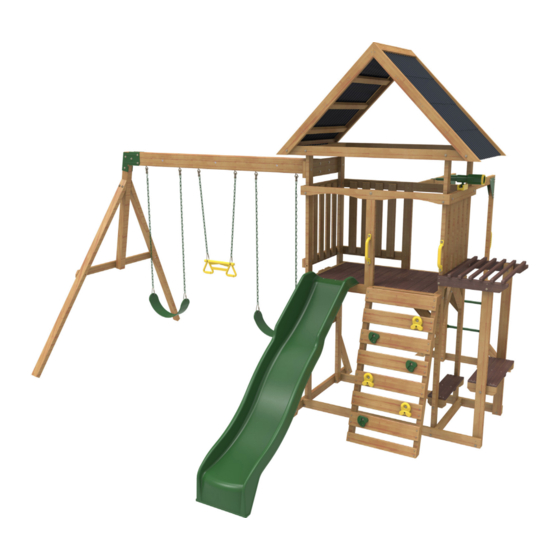
L AW N M E A D O W P L AY S E T - F 2 9 0 7 0
INSTALLATION AND OPERATING INSTRUCTIONS
28' 1"
8 .56m
14' 11-1/2"
4 .56m
10 - 14 Hrs
TWO PERSON
ASSEMBLY
KidKraft, Inc .
4630 Olin Road
Dallas, Texas 75244 USA
customerservice@kidkraft .com
canadacustomerservice@kidkraft .com
1 .800 .933 .0771
972 .385 .0100
For online parts replacement visit
https://parts .kidkraft .com/
WARNING
Manufacturer contact information provided below.
OBSTACLE FREE SAFETY ZONE - 28' 1" x 25' 2" (8.56m x 7.67m) area requires Protective Surfacing. See page 3.
MAXIMUM VERTICAL FALL HEIGHT - 6' 4" (1.93m)
CAPACITY - 9 Users Maximum, Ages 3 to 10;
12' 5/8"
Weight Limit 110 lbs. (49.9 kg) per child.
3 .67m
RESIDENTIAL HOME USE ONLY. Not intended for public areas such as schools, churches, nurseries, day cares or
parks.
WARNING. Only for domestic use.
KidKraft Netherlands BV
Olympisch Stadion 8
1076 DE Amsterdam
The Netherlands
europecustomerservice@kidkraft .com
+31 20 305 8620 M-F from 09:00 to 17:30
(GMT+1)
For online parts replacement visit
https://parts .kidkraft .eu/
To reduce the risk of serious injury or death, you must read and
follow these instructions. Keep and refer to these instructions
often and give them to any future owner of this play system.
FOR OUTDOOR FAMILY DOMESTIC USE ONLY
Table of Contents
Warnings and Safe Play Instructions . . . . . pg . 2
Protective Surfacing Guidelines . . . . . . . . pg . 3
Instructions for Proper Maintenance . . . . . pg . 4
About Our Wood - Limited Warranty . . . . . pg . 5
Keys to Assembly Success . . . . . . . . . . . . pg . 7
Part ID . . . . . . . . . . . . . . . . . . . . . . . . . . . . pg . 8
Step-By-Step Instructions . . . . . . . . . . . . pg . 13
9409070
Rev 09/07/2020
Advertisement

Related Manuals for KidKraft LAWNMEADOW F29070


Summary of Contents for KidKraft LAWNMEADOW F29070
-
Page 1: Table Of Contents
Warnings and Safe Play Instructions . . . . . pg . 2 Protective Surfacing Guidelines . . . . . . . . pg . 3 KidKraft, Inc . KidKraft Netherlands BV Instructions for Proper Maintenance . -
Page 2: Warnings And Safe Play Instructions
Warnings and Safe Play Instructions CONTINUOUS ADULT SUPERVISION REQUIRED. Most serious injuries and deaths on playground equipment have occurred while children were unsupervised! Our products are designed to meet mandatory and voluntary safety standards. Complying with all warnings and recommendations in these instructions will reduce the risk of serious or fatal injury to children using this play system. -
Page 3: Protective Surfacing Guidelines
Protective Surfacing - Reducing Risk of Serious Head Injury From Falls One of the most important things you can do to reduce the likelihood of serious head injuries is to install shock-absorbing protective surfacing under and around your play equipment. The protective surfacing should be applied to a depth that is suitable for the equipment height in accordance with ASTM F1292. -
Page 4: Instructions For Proper Maintenance
Instructions for Proper Maintenance Your KidKraft Play System is designed and constructed of quality materials with your child’s safety in mind. As with all outdoor products used by children, it will weather and wear. To maximize the enjoyment, safety and life of your Play Set, it is important that you, the owner, properly maintain it. -
Page 5: About Our Wood - Limited Warranty
About Our Wood KidKraft Premium Play Systems uses only premium playset lumber, ensuring the safest product for your children’s use. Although we take great care in selecting the best quality lumber available, wood is still a product of nature and susceptible to weathering which can change the appearance of your set. - Page 6 KidKraft Limited Warranty MISSING OR DAMAGED PARTS: KidKraft will replace any parts within 90 days from date of purchase found to be missing from or damaged in the original packaging. See Fig.1 Fig. 1 Product Age (All Parts) Consumer Pays...
-
Page 7: Keys To Assembly Success
Keys to Assembly Success Tools Required • Tape Measure • #1 Phillips, #2 Robertson • Open End Wrench • 3/16” Hex Key • Carpenters Level and Screwdriver (1/2” & 9/16”) • 8’ Step Ladder • Carpenters Square • Ratchet with extension •... -
Page 8: Part Id
Part Identification (Reduced Part Size) Part Identification (Reduced Part Size) Part Identification (Reduced Part Size) Part Identification (Reduced Part Size) 2x - 9835 - 31 .8 x 76 .2 x 1612 .9 mm - 3739835 1-1/4 x 3 x 63-1/2" 1x - 9836 - 31 .8 x 76 .2 x 1219 .2 mm - 3739836 1-1/4 x 3 x 48"... - Page 9 Part Identification (Reduced Part Size) Part Identification (Reduced Part Size) Part Identification (Reduced Part Size) Part Identification (Reduced Part Size) 12x - 9852 - 15 .9 x 76 .2 x 673 .1 mm - 3739852 5/8 x 3 x 26-1/2" 1x - 9853 - 15 .9 x 114 .3 x 593 .6 mm - 3739853 5/8 x 4-1/2 x 23-3/8"...
- Page 10 Part Identification (Reduced Part Size) Part Identification (Reduced Part Size) Part Identification (Reduced Part Size) Part Identification (Reduced Part Size) 2x - 9871 - 38 .1 x 38 .1 x 1090 mm - 3739871 1-1/2 x 1-1/2 x 42-15/16" 1x - 9872 - 31 .8 x 76 .2 x 1090 mm - 3739872 1-1/4 x 3 x 42-15/16"...
- Page 11 Hardware Identification (Actual Size) 4 .8mm 7 .9mm 6x FW0 - 3/16" - (51103100) 19x TN2 - 5/16" (54503300) 22x LW2 - 5/16" - (51303300) 7 .9mm 7 .9mm 77x FW1 - 1/4" - (51103200) 21x LN2 - 5/16" (54303300) 6 .4mm 6 .4mm 71x LW1 - 1/4"...
- Page 12 Part Identification (Reduced Part Size) 1x - 3329070 (6 Pk) 2x - 9320130 1x - 3320353 1x - 9320374 1x - #2 x 2" (9200014) 1x - 3320161 1x - 3200818 (8Pk) 1x - 3200143 1x - 3200145 (2pk) 1x - 9200143 1x - 9200144 1x - 3200173 2x 20"...
-
Page 13: Step-By-Step Instructions
• The carton I .D . stamp is located on the end of each carton . The tracking number is located on the KidKraft ID Plaque (9320374) . • Please retain this information for future reference . You will need this information if you contact the Consumer Relations Department . - Page 14 Step 2 Make sure the assembly is square. 9886 9839 9839 9886 9886 9839 Wood Parts Hardware 6.4 x 63.5 mm (1/4 x 2-1/2”) (FW1, LW1, TN1) 31.8 x 76.2 x 2336.8 mm (1-1/4 x 3 x 92”) 9839 31.8 x 76.2 x 698.5 mm (1-1/4 x 3 x 27-1/2”) 9886...
- Page 15 Step 3 9840 Note hole orientation 9840 9839 9839 Wood Parts Hardware 6.4 x 63.5 mm (1/4 x 2-1/2”) (FW1, LW1, TN1) 31.8 x 76.2 x 698.5 mm (1-1/4 x 3 x 27-1/2”) 9840...
- Page 16 Step 4 Make sure the assembly is square. 9870 9886 9841 9886 9875 9875 9841 9875 Top View 9870 9886 9841 9886 9875 Note hole orientation Wood Parts Hardware 6.4 x 63.5 mm (1/4 x 2-1/2”) 31.8 x 76.2 x 730.3 mm (1-1/4 x 3 x 28-3/4”) 31.8 x 76.2 x 698.5 mm (1-1/4 x 3 x 27-1/2”) 9841 9886...
- Page 17 Step 5 9842 9842 9875 Notice Angle Orientation Wood Parts Hardware 6.4 x 63.5 mm (1/4 x 2-1/2”) (FW1, LW1, TN1) 31.8 x 76.2 x 1257.3 mm (1-1/4 x 3 x 49-1/2”) 9842...
- Page 18 Step 6 9840 Note hole orientation 9840 9875 9875 Wood Parts Hardware 6.4 x 63.5 mm (1/4 x 2-1/2”) (FW1, LW1, TN1) 31.8 x 76.2 x 698.5 mm (1-1/4 x 3 x 27-1/2”) 9840...
- Page 19 Step 7 9838 9836 9837 Bottom View 9838 9837 9836 Note hole orientation Wood Parts Hardware 7.9 x 34.9 mm (5/16 x 1-3/8”) (LW2, FW2, TN2) 31.8 x 76.2 x 1219.2 mm (1-1/4 x 3 x 48”) 9836 31.8 x 76.2 x 863.6 mm (1-1/4 x 3 x 34”) 9837 #8 x 25.4 mm (#8 x 1”) 31.8 x 76.2 x 1282.8 mm (1-1/4 x 3 x 50-1/2”)
- Page 20 Step 8 9876 9847 9848 9846 Top View 9876 9848 9846 9847 Note hole orientation Wood Parts Hardware 7.9 x 34.9 mm (5/16 x 1-3/8”) 31.8 x 76.2 x 695.3 mm (1-1/4 x 3 x 27-3/8”) 31.8 x 76.2 x 1282.8 mm (1-1/4 x 3 x 50-1/2”) 9846 9876 (LW2, FW2, TN2)
- Page 21 Step 9 Hardware 6.4 x 108 mm (1/4 x 4-1/4”) (LW1, FW1, TN1) 10 x #8 x 63.5 mm (#8 x 2-1/2”)
- Page 22 Step 10 9835 9835 9835 Wood Parts Hardware 31.8 x 76.2 x 1612.9 mm (1-1/4 x 3 x 63-1/2”) 6.4 x 108 mm (1/4 x 4-1/4”) (LW1, FW1, TN1) 9835 #8 x 63.5 mm (#8 x 2-1/2”)
- Page 23 Step 11 Pre-drill each hole using a 3/16” drill bit for WL5. 2607 9842 2607 2607 2607 Wood Parts Hardware 6.4 x 63.5 mm (1/4 x 2-1/2”) (FW1, LW1, TN1) 31.8 x 76.2 x 558.8 mm (1-1/4 x 3 x 22”) 2607 6.4 x 63.5 mm (1/4 x 2-1/2”)
- Page 24 Step 12 9871 9871 (Hidden) 9871 WB10 WB10 Wood Parts Hardware 7.9 x 66.7 mm (5/16 x 2-5/8”) (FW2, TN2) 38.1 x 38.1 x 1090 mm (1-1/2 x 1-1/2 x 42-15/16”) WB10 9871 #12 x 50.8 mm (#12 x 2”)
- Page 25 Step 13 5/8” 16 mm 9872 9872 Hardware Wood Parts 31.8 x 76.2 x 1090 mm (1-1/4 x 3 x 42-15/16”) #8 x 76.2 mm (#8 x 3”) 9872...
- Page 26 Step 14 9873 Inside View 9873 9873 9873 9873 Hardware Wood Parts 31.8 x 76.2 x 381 mm (1-1/4 x 3 x 15”) #8 x 76.2 mm (#8 x 3”) 9873 #8 x 50.8 mm (#8 x 2”)
- Page 27 Step 15 9874 (Hidden) 9874 9874 9874 9874 Hardware Wood Parts 6.4 x 63.5 mm (1/4 x 2-1/2”) (FW1, LW1, TN1) 31.8 x 76.2 x 381 mm (1-1/4 x 3 x 15”) 9874 #8 x 76.2 mm (#8 x 3”) #8 x 50.8 mm (#8 x 2”)
- Page 28 Step 16 IMPORTANT! Follow hole pattern Pre-drill holes using a 9853 1/8” drill bit. 9868 9854 Do not attach Put aside until Step 20 9853 9868 9868 9868 9868 9868 9868 9854 9845 9854 Hardware Wood Parts 15.9 x 76.2 x 593.6 mm (5/8 x 3 x 23-3/8”) 15.9 x 114.3 x 593.6 mm (5/8 x 4-1/2 x 23-3/8”) 28 x #12 x 50.8mm (#12 x 2”)
- Page 29 S20 X 4 Step 17 9867 9867 Hardware Wood Parts 15.9 x 76.2 x 593.6 mm (5/8 x 3 x 23-3/8”) #8 x 35mm (#8 x 1-3/8”) 9867...
- Page 30 Step 18 Note: Make sure all hardware is used to properly secure each rock. 3329070 3329070 Hardware Other Parts 7.9mm x 32 mm (5/16 x 1-1/4”) (FW0, LW1, BN1) 3329070 #8 x 25.4 mm (#8 x 1”)
- Page 31 Step 19 Flush Hardware #8 x 50.8 mm (#8 x 2”)
- Page 32 Step 20 Pre-drill holes using a 1/8” drill bit. 9853 Hardware #12 x 50.8mm (#12 x 2”)
- Page 33 Step 21 9318 9318 9318 Wood Parts Hardware 31.8 x 363 x 696.5 mm (1-1/4 x 14-21/64 x 27-7/16”) #8 x 35mm (#8 x 1-3/8”) 9318 12 x #8 x 50.8 mm (#8 x 2”)
- Page 34 Step 22 9852 9852 Beveled edge faces out Evenly space 9852 9852 9852 9852 Wood Parts Hardware 15.9 x 76.2 x 673.1 mm (5/8 x 3 x 26-1/2”) 16 x #8 x 34.9 mm (#8 x 1-3/8”) 9852...
- Page 35 Step 23 Evenly space 9852 Beveled edge faces out 9852 Wood Parts Hardware 15.9 x 76.2 x 673.1 mm (5/8 x 3 x 26-1/2”) 16 x #8 x 34.9 mm (#8 x 1-3/8”) 9852...
- Page 36 Step 24 Evenly space 9852 9852 Beveled edge faces out Wood Parts Hardware 15.9 x 76.2 x 673.1 mm (5/8 x 3 x 26-1/2”) 16 x #8 x 34.9 mm (#8 x 1-3/8”) 9852...
- Page 37 Step 25 9849 9849 9850 9850 9849 9850 Hardware Wood Parts 6.4 x 63.5 mm (1/4 x 2-1/2”) (FW1, LW1, TN1) 31.8 x 76.2 x 539.8 mm (1-1/4 x 3 x 21-1/4”) 9849 31.8 x 76.2 x 1371.6 mm (1-1/4 x 3 x 54”) 9850 #8 x 50.8 mm (#8 x 2”)
- Page 38 Step 26 (Hidden) 9849 9850 Hardware 6.4 x 63.5 mm (1/4 x 2-1/2”) (FW1, LW1, TN1) #8 x 50.8 mm (#8 x 2”) 6.4 x 108 mm (1/4 x 4-1/4”) (FW1, LW1, TN1) #8 x 63.5 mm (#8 x 2-1/2”)
- Page 39 Step 27 9855 9855 9855 9856 9878 9856 9858 9858 9857 9879 9857 Wood Parts Hardware 15.9 x 76.2 x 633 mm (5/8 x 3 x 24-15/16”) 15.9 x 76.2 x 544.1 mm (5/8 x 3 x 21-7/16”) 25 x #8 x 34.9 mm (#8 x 1-3/8”) 9855 9858...
- Page 40 Step 28 Hardware 6.4 x 63.5 mm (1/4 x 2-1/2”) (FW1, LW1, TN1) #12 x 50.8 mm (#12 x 2”) 6.4 x 108 mm (1/4 x 4-1/4”) (FW1, LW1, TN1)
- Page 41 Step 29 9851 9851 9851 9851 9851 9851 Evenly space all boards Wood Parts Hardware 25.4 x 25.4 x 793.8 mm (1 x 1 x 31-1/4”) 12 x #8 x 50.8 mm (#8 x 2”) 9851...
- Page 42 Step 30 9977 9977 Wood Parts Hardware #8 x 35 mm (#8 x 1-3/8”) 15.9 x 63.5 x 696.5mm (5/8 x 2-1/2 x 27-7/16”) 9977...
- Page 43 Step 31 x 2 9976 9844 9843 9844 9843 Wood Parts Hardware 31.8 x 76.2 x 1638.4 mm (1-1/4 x 3 x 64-1/2”) 6.4 x 63.5 mm (1/4 x 2-1/2”) (FW1, LW1, TN1) 9843 31.8 x 76.2 x 1221.3 mm (1-1/4 x 3 x 48-1/16”) 9844 #8 x 76.2 mm (#8 x 3”) 31.8 x 76.2 x 1221.3 mm (1-1/4 x 3 x 48-1/16”)
- Page 44 Step 32 9866 9869 9869 9869 9869 9869 9863 9869 9863 9869 Flush 9866 9863 Flush Wood Parts Hardware 31.8 x 50.8 x 762.1 mm (1-1/4 x 2 x 30”) 32 x #8 x 50.8 mm (#8 x 2”) 9863 38.1 x 76.2 x 762.1 mm (1-1/2 x 3 x 30”) 9866 31.8 x 50.8 x 760.1 mm (1-1/4 x 2 x 29-15/16”)
- Page 45 Step 33 3339070 Center the roof 3339070 Pre-drill each hole using a 1/8” drill bit. Hardware Other Parts #8 x 22.2 mm (#8 x 7/8”) 3339070...
- Page 46 Step 34 3339070 Pre-drill each hole using a 1/8” drill bit . Hardware #8 x 22.2 mm (#8 x 7/8”)
- Page 47 Step 35 3339070 Pre-drill each hole using a 1/8” drill bit . Hardware #8 x 22.2 mm (#8 x 7/8”)
- Page 48 Step 36 3339070 Pre-drill each hole using a 1/8” drill bit . Hardware #8 x 22.2 mm (#8 x 7/8”)
- Page 49 Step 37 3339070 Center the roof 3339070 Pre-drill each hole using a 1/8” drill bit. Hardware #8 x 22.2 mm (#8 x 7/8”)
- Page 50 Step 38 3339070 Pre-drill each hole using a 1/8” drill bit . Hardware #8 x 22.2 mm (#8 x 7/8”)
- Page 51 Step 39 3339070 Pre-drill each hole using a 1/8” drill bit . Hardware #8 x 22.2 mm (#8 x 7/8”)
- Page 52 Step 40 3339070 Pre-drill each hole using a 1/8” drill bit . Hardware #8 x 22.2 mm (#8 x 7/8”)
- Page 53 Step 41 Pre-drill each hole using 9864 a 1/8” drill bit. 9865 Flush Flush 9865 9864 Wood Parts Hardware 15.9 x 76.2 x 772.9 mm (5/8 x 3 x 30-7/16”) #8 x 50.8 mm (#8 x 2”) 9864 15.9 x 63.5 x 772.9 mm (5/8 x 2-1/2 x 30-7/16”) 9865...
- Page 54 Step 42 (Hidden) Hardware 6.4 x 108 mm (1/4 x 4-1/4”) (FW1, LW1, TN1)
- Page 55 Step 43 3200127 9859 9859 3200127 9859 Wood Parts Hardware Other Parts 31.8 x 76.2 x 1066.8 mm (1-1/4 x 3 x 42”) 6.4 x 63.5 mm (1/4 x 2-1/2”) 9859 3200127...
- Page 56 Step 44 3200127 9860 9860 3200127 9860 Wood Parts Hardware Other Parts 31.8 x 76.2 x 1930.4 mm (1-1/4 x 3 x 76”) 6.4 x 63.5 mm (1/4 x 2-1/2”) 9860 3200127...
- Page 57 Step 45 Be sure to keep the bolts loose. 9862 9862 9860 Wood Parts Hardware 15.9 x 76.2 x 1015 mm (5/8 x 3 x 39-15/16”) 6.4 x 88.9 mm (1/4 x 3-1/2”) (LW1, FW1, TN1) 9862...
- Page 58 Step 46 Once lag screws are installed tighten all bolts. 9861 9862 9861 Pre-drill hole using a 3/16” drill bit for WL5. 9862 9861 9861 Wood Parts Hardware 31.8 x 76.2 x 457.2 mm (1-1/4 x 3 x 18”) 6.4 x 50.8 mm (1/4 x 2”) (LW1, FW1, TN1) 9861 6.4 x 63.5 mm (1/4 x 2-1/2”)
- Page 59 Step 47 3200184 3200184 Hardware Other Parts 10 x 7.9 x 50.8 mm (5/16 x 2”) (2 x FW2, LW2, LN2) 3200184...
- Page 60 Step 48 Flush 9200141 Hardware Other Parts 6.4 x 50.8 mm (1/4 x 2”) (2 x FW1, LN1) 9200141...
- Page 61 Step 49 9200141 Hardware 6.4 x 31.8 mm (1/4 x 1-1/4”) (LW1, FW1, TN1)
- Page 62 Step 50 9877 Notice Angle Orientation 3202001 3202001 Make sure triangle is tight against beam WARNING: For your child’s safety, orientate the swing hangers as shown to ensure your swing will have proper swing motion when installed. Failure to do so could result in premature failure of the swing hanger or swing chain.
- Page 63 Step 51 IT IS IMPORTANT THAT THIS BOLT IS ATTACHED. IT WILL MINIMIZE CHECKING OF WOOD. 3320353 Hardware Other Parts 7.9mm x 76.2mm (5/16 x3”)(FW2 , TN2) 3320353 #6 x 25.4 mm (#6 x 1”)
- Page 64 Step 52 3200145 Hardware Other Parts 7.9 x 95 mm (5/16 x 3-3/4”) (2 x FW2, LN2) 3200145...
- Page 65 Step 53 2613 2615 2613 Wood Parts Hardware 50.8 x 76.2 x 2201.9 mm (2 x 3 x 86-11/16”) 7.9 x 139.7 mm (5/16 x 5-1/2”) (LW2, FW2, TN2) 2613 76.2 x 76.2 x 1294.3 mm (3 x 3 x 50-15/16”) 2615...
- Page 66 Step 54 IT IS IMPORTANT THAT THESE BOLTS ARE ATTACHED. THEY WILL MINIMIZE CHECKING OF WOOD. 2616 2616 Wood Parts Hardware 23.8 x 82.6 x 1181.1mm (15/16 x 3-1/4 x 46-1/2”) 7.9mm x 101.6mm (5/16 x 4”) (LW2, FW2, TN2) 2616 7.9mm x 76.2mm (5/16 x 3”) (LW2, FW2, TN2)
- Page 67 Step 55 9200143 G21 G21 9200144 Hardware Other Parts 7.9 x 95 mm (5/16 x 3-3/4”) (2 x FW2, LN2) 9200143 9200144...
- Page 68 Step 56 Hardware 7.9 x 44.5 mm (5/16 x 1-3/4”) (2 x FW2, LN2)
- Page 69 Step 57 3200173 3200173 (48") (48") 3200173 9320130 Caution: Threaded Quick Links must be installed with the gate completely down covering the 3200173 threads and tighten as instructed. 3200020 3200173 3200020 Quick Link Threaded Quick Links Tighten Threaded Quick attach to seat . Link using adjustable wrench 9320130...
- Page 70 Step 58 3200173 (20") 3200173 9724904 Caution: Threaded Quick Links must be installed with the gate completely down covering the 3200173 3200173 threads and tighten as instructed. 3200022 3200173 3200022 9724904 Quick Link Threaded Quick Links Tighten Threaded Quick attach to Acro Bar . Link using adjustable wrench Other Parts...
- Page 71 Step 59 Note: Pre-drill all holes using a 1/8” drill bit before installing the pan screws. Place Slide centred in the opening. 7310149 7310149 Other Parts Hardware #12 x 50.8 mm (#12 x 2”) 7310149...
- Page 72 Step 60 3320240 3320240 8” (203mm) Pre-drill each hole using a 1/8” drill bit. Hardware Other Parts 1/4 x 1-3/8” (6.4 x 35 mm) (FW1) 3320240...
- Page 73 Step 61 3320240 3320240 47-1/4” (1 .2m) Pre-drill each hole using a 1/8” drill bit. Hardware Other Parts 1/4 x 1-3/8” (6.4 x 35 mm) (FW1) 3320240...
- Page 74 Step 62 3320161 Other Parts Hardware #8 x 35 mm (#8 x 1-3/8”) 3320161...
- Page 75 Nombre maximum d’ utilisateurs, installation et d'utilisation; d'autres informations sont disponibles sur: Contáctenos en: KidKraft www.KidKraft.com Dallas, TX 75244, Estados Unidos Contact us at: KidKraft Dallas, TX 75244 USA 1-800-933-0771 1-800-933-0771 Tracking Number: Número de Numèro de Suivi:...
- Page 76 Step 64 MOVE FORT TO FINAL LOCATION PRIOR TO STAKING FINAL LOCATION MUST BE LEVEL GROUND Warning! To prevent tipping and avoid potential injury, stakes must be driven 13”(330mm) into ground. Digging or driving stakes can be dangerous if you do not check first for under-ground wiring, cables or gas lines.
- Page 77 NOTES...
- Page 78 NOTES...
- Page 79 NOTES...
- Page 80 Would you recommend the purchase of our products to friends and family? Comments: MAIL TO: Fill out your registration card online at KidKraft https://prdregistration.kidkraft.com/ 4630 Olin Road Dallas, TX 75244 United States KidKraft would like to say Thank You for Attention: Customer Service your time and feedback.
Need help?
Do you have a question about the LAWNMEADOW F29070 and is the answer not in the manual?
Questions and answers