Advertisement
Quick Links
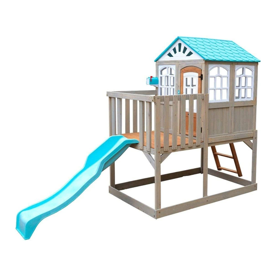
HIGHLINE RETREAT F29060EF
INSTALLATION AND OPERATING INSTRUCTIONS
12' 10.73"
3.930
26' 0.20"
7.930
KidKraft, Inc.
4630 Olin Road
Dallas, Texas 75244 USA
customerservice@kidkraft.com
canadacustomerservice@kidkraft.com
1.800.933.0771
972.385.0100
For online parts replacement visit
https://parts.kidkraft.com/
WARNING
owner of this play system. Manufacturer contact information provided below.
OBSTACLE FREE SAFETY ZONE - 26'0.20" x 17'1.24" (7.930 x 5.213 m) area requires
17' 1.24"
Protective Surfacing. See Page 3
3' 11.77"
5.213
1.213
MAXIMUM VERTICAL FALL HEIGHT - 2'11.47"(0.9 m)
-
8 Users Maximum, Ages 3 to 10; Weight Limit 110 lbs. (49.9 kg) per child.
CAPACITY
RESIDENTIAL HOME USE ONLY. Not intended for public areas such as schools,
churches, nurseries, day cares or parks.
Warning. Only for domestic use.
KidKraft Netherlands BV
Olympisch Stadion 29
1076DE Amsterdam
The Netherlands
europecustomerservice@kidkraft.com
+31 20 305 8620 M-F from 09:00 to 17:30
(GMT+1)
For online parts replacement visit
https://parts.kidkraft.eu/
To reduce the risk of serious injury or death, you must
read and follow these instructions. Keep and refer to
these instructions often and give them to any future
Table of Contents
Warnings and Safe Play Instructions . . . . . pg. 2
Protective Surfacing Guidelines . . . . . . . . . pg. 3
Instructions for Proper Maintenance . . . . . . pg. 4
About Our Wood - Limited Warranty . . . .pg. 5-6
Battery Instruction and Warranty . . . . . . . . pg. 7
Keys to Assembly Success . . . . . . . . . . . . . pg. 8
Part ID . . . . . . . . . . . . . . . . . . . . . . . . . pg. 11-14
Step-By-Step Instructions . . . . . . . . . . pg. 15-47
Installation of I.D./Warning Plaque . . . Final Step
9409060
2.5 - 4 Hrs
TWO PERSON
ASSEMBLY
Rev 09/05/2020
Advertisement

Related Manuals for KidKraft HIGHLINE RETREAT


Summary of Contents for KidKraft HIGHLINE RETREAT
-
Page 1: Table Of Contents
HIGHLINE RETREAT F29060EF INSTALLATION AND OPERATING INSTRUCTIONS WARNING To reduce the risk of serious injury or death, you must read and follow these instructions. Keep and refer to 12' 10.73" these instructions often and give them to any future 3.930 owner of this play system. -
Page 2: Warnings And Safe Play Instructions
Warnings and Safe Play Instructions CONTINUOUS ADULT SUPERVISION REQUIRED. Most serious injuries and deaths on playground equipment have occurred while children were unsupervised! Our products are designed to meet mandatory and voluntary safety standards. Complying with all warnings and recommendations in these instructions will reduce the risk of serious or fatal injury to children using this play system. -
Page 3: Protective Surfacing Guidelines
Protective Surfacing - Reducing Risk of Serious Head Injury From Falls One of the most important things you can do to reduce the likelihood of serious head injuries is to install shock-absorbing protective surfacing under and around your play equipment. The protective surfacing should be applied to a depth that is suitable for the equipment height in accordance with ASTM F1292. -
Page 4: Instructions For Proper Maintenance
Instructions for Proper Maintenance Your KidKraft Play System is designed and constructed of quality materials with your child’s safety in mind. As with all outdoor products used by children, it will weather and wear. To maximize the enjoyment, safety and life of your Play Set, it is important that you, the owner, properly maintain it. -
Page 5: About Our Wood - Limited Warranty
About Our Wood KidKraft Premium Play Systems uses only premium playset lumber, ensuring the safest product for your children’s use. Although we take great care in selecting the best quality lumber available, wood is still a product of nature and susceptible to weathering which can change the appearance of your set. - Page 6 KidKraft Limited Warranty MISSING OR DAMAGED PARTS: KidKraft will replace any parts within 90 days from date of purchase found to be missing from or damaged in the original packaging. See Fig.1 Fig. 1 Product Age (All Parts) Consumer Pays...
-
Page 7: Battery Instruction And Warranty
Battery Instruction and Warranty This device complies with Part 15 of the FCC Rules. Operation is subject to the following two conditions: (1) This device may not cause harmful interference, and (2) this device must accept any interference received, including interference that may cause undesired operation. NOTE: This equipment has been tested and found to comply with the limits for a Class B digital device, pursuant to part 15 of the FCC Rules. -
Page 8: Keys To Assembly Success
Keys to Assembly Success Tools Required • Tape Measure • #1 Phillips, #2 Robertson • Open End Wrench • 3/16” Hex Key • Carpenters Level and Screwdriver (1/2” & 9/16”) • 8’ Step Ladder • Carpenters Square • Ratchet with extension •... -
Page 11: Part Id
Part Identification (Reduced Part Size) 2pc. - 021 - 5/8 x 4-1/2 x 76-7/8" (15.9 x 114.3 x 1952.6mm) - Lower Front Back - Box 2 - 3569327 2pc. - 041 - 5/8 x 4-1/2 x 47-3/4" (15.9 x 114.3 x 1213.4mm) - Lower Side - Box 2 - 3569328 2pc. - Page 12 Part Identification (Reduced Part Size) 1pc. - 111 - 1-3/8 x 3 x 39-7/8" (34.9 x 76.2 x 1013mm) - Right Access - Box 1 - 3739346 3pc. - 113 - 1 x 3-1/4 x 19-1/4" (23.8 x 82.6 x 488.8mm) - Tread - Box 1 - 3739347 1pc.
- Page 13 1x - Mailbox (3321910) 1x - Superfold Roof (P-U-4604-SBT) 3x - #6 x 9 mm Self Tapping Screw (52042902) - KidKraft ID Plaque ( 9320374 ) - Mailbox Other Half (9321923B) - Mailbox Flag Half (9321923A) 1x - Mailbox 2 Door...
- Page 14 Hardware Identification (Actual Size) #6 x 1" 2pc. S18 -Wood Screw (25mm) - (52013910) #8 x 7/8" (22mm) 22pc. S0 - Truss Head Screw - (52933505) #8 x 2-1/2" (64mm) 44pc. S3 - Wood Screw - (52043522) 202pc. S20 - Wood Screw #8 x 1-3/8” (35mm) - (52043516) #8 x 3"...
-
Page 15: Step-By-Step Instructions
Before you discard your cartons fill out the form below. • The carton I.D. stamp is located on the end of each carton.The tracking number is located on the KidKraft ID Plaque (9320374). • Please retain this information for future reference. You will need this information if you contact the Consumer Relations Department. - Page 16 Step 2: Back Wall Assembly Note: It is important to note hole orientation for the following step. A: Place (021) Lower Front Back so that one end is over (023) Upright Long and the other end is over (022) Upright Short. Attach each end using 1 (H2) 1/4 x 2” Hex Bolt (with lock washer, flat washer and t-nut) and 1 (S20) #8 x 1-3/8”...
- Page 17 Step 3: Front Wall Assembly Note: It is important to note hole orientation for the following step. A: Refer to Step 2 but placing (023) Upright Long and (022) Upright Short on the opposite ends of the (021) Lower Front Back. Attach each end using 1 (H2) 1/4 x 2” Hex Bolt (with lock washer, flat washer and t-nut) and 1 (S20) #8 x 1-3/8”...
- Page 18 Step 4: Side Wall Assembly Part 1 A: With a helper hold Front and Back Wall Assemblies in position as shown in fig. 4.1. B: Place 1 (041) Lower Side across the bottom of each end and attach using 2 (H15) 1/4 x 3- 3/4” Hex Bolts (with lock washer, flat washer and t-nut) and 2 (S20) #8 x 1 -3/8”...
- Page 19 Step 4: Side Wall Assembly Part 2 C: Place 1 (042) End Floor Support at each end of the assembly so they are flush to the (024) Floor Support Longs. Attach each (042) End Floor Support using 6 (S3) #8 x 2 -1/2” Wood Screws per board as shown in fig. 4.3 and 4.5.
- Page 20 Step 4: Side Wall Assembly Part 3 E: Attach (043) SL Barrier Top to (023) Upright Longs using 2 (H8) 1/4 x 4- 1/4” Hex Bolts (with lock washer, flat washer and t-nut) making sure that all boards are flush at the top. (fig. 4.6 and fig. 4.7) Flush Fig.
- Page 21 Step 5: Floor Assembly A: Place 1 (051) Floor Board so that it fits between the (022) Upright Shorts and is flush to the edge of (042) End Floor Support. Attach (051) Floor Board to (024) Floor Support Longs using 6 (S20) #8 x 1-3/8” Wood Screws. (fig.
- Page 22 Step 6: Attach Gussets A: Place 1 (061) Gusset Long so that it’s flush to the outside edges of the (042) Floor End Support and the (023) Upright Long. Attach using 2 (S4) #8 x 3” Wood Screws on the inside holes and 2 (S11) #8 x 2” Wood Screws in the outer holes.
- Page 23 Step 7: Playhouse Assembly Part 1 A: With a helper lift (071) Panel Assembly up onto the righthand side of the playhouse floor and place it upright with the open end at the front. (fig. 7.1) B: On the inside of (023) Upright Long, place 1 (072) Side Barrier Top so that it’s tight to (043) SL Barrier and all boards are flush at the top.
- Page 24 Step 7: Playhouse Assembly Part 2 D: Make sure that (071) Panel Assembly is fully open and that each wall is flush to the edges of the (051) Floor Boards. Check to ensure that the assembly is square and install 4 (S3) #8 x 2 – ½” Wood Screws in each end wall as shown in fig.
- Page 25 Step 7: Playhouse Assembly Part 3 E: Center 1 Corner Bracket over the partition on the inside of each end wall. Attach Corner Bracket to (071) Panel Assembly and (051) Floor Boards using 3 (S0) #8 x 7/8” Truss Screws per bracket. (fig. 7.6 and fig. 7.7) Fig.
- Page 26 Step 7: Playhouse Assembly Part 4 F: From outside the assembly attach each (022) Upright Short to (071) Panel Assembly using 1 (S3) #8 x 2 -1/2” Wood Screw in the outside hole and 1 (S11) #8 x 2” Wood Screw for the inside hole. (fig. 7.8) Fig.
- Page 27 Step 7: Playhouse Assembly Part 5 G: On the outside Front Wall, tight to (022) Upright Short, center 1 (073) Center Tie over the bottom of (071) Panel Assembly, (051) Floor Boards and (024) Floor Support Long. Attach using 8 (S20) #8 x 1 -3/8” Wood Screws.
- Page 28 Step 7: Playhouse Assembly Part 6 H: Taking note of hole orientation, place 1 (074) Upright Center against the end of (073) Center Tie, making sure that its flush with the edge of (071) Panel Assembly. The bottom of the board should be on the inside of (021) Lower Front Back.
- Page 29 Step 7: Playhouse Assembly Part 7 K: From inside the assembly on the back wall, measure 15” (381mm) up from the floor boards and center 1 Flat Panel Bracket over the partition. Attach using 4 (S0) #8 x 7/8” Truss Screws. (fig. 7.12 and fig. 7.13) Fig.
- Page 30 Step 8: Deck Wall Assembly Part 1 A: On the front and back deck walls, evenly space and install 5 (081) SL Barriers using 4 (S20) #8 x 1-3/8” Wood Screws per board, making sure that all boards are flush to the top of (072) Side Barriers. There should be a 63.5mm space between each board.
- Page 31 Step 8: Deck Wall Assembly Part 2 B: On the End Wall of the Deck Assembly measure 84mm in from the (022) Upright Shorts and install 1 (082) End Barrier per side, making sure that the notched out end is at the bottom and fits over (042) End Floor Support and that the top of the board is behind (043) SL Barrier Top.
- Page 32 Step 9: Soffit Assembly A: Center (092) End Wall Soffits on each end of (071) Panel Assembly, making sure that they are flush to the inside wall. Attach each soffit using 4 (S11) #8 x 2” Wood Screws. (fig. 9.1 and fig. 9.2) B: Place (091) Side Wall Soffits along the top of the front and back walls ensuring that they are flush to the inside wall.
- Page 33 Step 10: Roof Assembly Part 1 A: Open Superfold Roof and place it into position over (071) Panel Assembly. (fig. 10.1, fig. 10.2, and fig. 10.3) B: Attach Roof to each (092) End Wall Soffit using 2 (S11) #8 x 2” Wood Screws per side. (fig. 10.3 and fig. 10.4.) Superfold Roof Fig.
- Page 34 Step 10: Roof Assembly Part 2 C: On each end of the Superfold Roof attach the bottom of the Sunburst to (091) Side Wall Soffit using 6 (S0) #8 x 7/8” Truss Screws per side. (fig. 10.5) Fig. 10.5 Superfold Roof Note: Roof is hidden Repeat Step C for the Other Side.
- Page 35 Step 11: Access Ladder Assembly A: Place (112) Left Access on one side of 3 (113) Treads and (111) Right Access on the other side with the grooves facing in. (fig. 11.1) B: Fit each (113) Tread into grooves on both (111) and (112) Access Rails, making sure the top edge of the (113) Treads are flush to the front of the Access rails.
- Page 36 Step 12: Attach Access Ladder to Deck A: Place Access Ladder against (042) End Floor Support so that it’s centered in the opening and flush to the top of the board. Pre-drill using a 1/8”drill bit and attach using 2 (LS2) 1/4 x 2-1/2” Hex Lag Screw (with 1/4” Flat Washer).
- Page 37 Step 13: Attach Door Components Part 1 A: On the inside of (131) Door measure 13” up from the bottom and attach Catch Plate flush to the edge using 2 (S13) #6 x 5/8” Pan Screws. (fig. 13.1) B: On the inside of (131) Door measure 18” up from the bottom and attach 1 Door Handle using 2 (S13) #6 x 5/8”...
- Page 38 Step 13: Attach Door Components Part 2 C: On the outside of the (131) Door attach the second Door Handle at approximately the same place as the one on the inside. Use 2 (S13) #6 x 5/8” Pan Screws. (fig. 13.3) D: On the opposite side from the Door Handle, measure 2 -1/2”...
- Page 39 Step 13: Attach Door Components Part 3 E: In the opening for the door, measure 5/8” from the top of the bottom door frame and maximum 5/8” from right side of the opening which would be the Door Hinge side and attach the remaining side of the hinges to (071) Panel Assembly using 3 (S13) #6 x 5/8”...
- Page 40 Step 13: Attach Door Components Part 4 F: In the notched out opening of (132) Door Stop attach the Magnetic Catch using 2 (S18) #6 x 1” Wood Screws. (fig. 13.9) Important: Use a hand held screw driver and DO NOT over tighten. G: On the inside of the assembly, attach (132) Door Stop to (071) Panel Assembly with 2 (S15) #8 x 1-3/4”...
- Page 41 Step 13: Attach Door Components Part 5 H: From outside the assembly attach Doorbell Trim using 2 (S13) #6 x 5/8” Pan Screws. (fig. 13.11) I: On the opposite side of the Doorbell Trim attach Doorbell 2 from the inside using 2 (S10) #8 x 1” Pan Screws. (fig.
- Page 42 Step 13: Attach Door Components Part 6 J: On the outside of (131) Door, below the window, attach KidKraft Logo Plaque using 2 (S37) #7 x 5/8” Pan Screws. (fig. 13.13 and fig. 13.14) Fig. 13.13 Fig. 13.14 KidKraft Logo Plaque...
- Page 43 Step 14: Attach Mail Box Part 1 A: Place both Mailbox Halves together and attach at the top with included hardware. (fig. 14.1) B: Snap Mailbox Door onto Mailbox Mount. (fig. 14.1) C: Place assembled Mailbox on Mailbox Mount and slide into place using the tabs and slots. (fig. 14.1) D: Attach Mailbox Flag to Mailbox with included hardware.
- Page 44 Step 14: Attach Mail Box Part 2 E: Measure 2” up from (072) Side Barrier Top and attach Mailbox to (071) Panel Assembly next to the window using 2 (S10) #8 x 1” Pan Screws in the top of the Mailbox. Attach the underside of the Mailbox using 1 (S10) #8 x 1” Pan Screw and 2 (S37) #7 x 5/8”...
- Page 45 Step 15: Attach Slide to Deck Note: Pre-drill all holes using a 1/8” drill bit before installing the pan screws. A: Place Slide centered in the opening in the Deck Wall. (fig. 15.1) B: Attach slide to fort using 2 (S7) #12 x 2” Pan Screws. (fig. 15.2 and fig. 15.3) Fig.
- Page 46 Step 16: Install Ground Stakes MOVE FORT TO FINAL LOCATION PRIOR TO STAKING FINAL LOCATION MUST BE LEVEL GROUND A: In the 6 places shown in fig. 16.1 drive the Rebar Ground Stakes 13” (330mm) into the ground against (041) Lower Side.
- Page 47 Contáctenos en: KidKraft www.KidKraft.com Dallas, TX 75244, Estados Unidos Contact us at: KidKraft Dallas, TX 75244 USA 1-800-933-0771 1-800-933-0771 Tracking Number: Número de Numèro de Suivi: seguimiento: Other Parts Hardware #7 x 5/8” Pan Screw 1 x KidKraft ID Plaque...
- Page 48 Would you recommend the purchase of our products to friends and family? Comments: MAIL TO: Fill out your registration card online at KidKraft https://prdregistration.kidkraft.com/ 4630 Olin Road Dallas, TX 75244 United States KidKraft would like to say Thank You for Attention: Customer Service your time and feedback.
Need help?
Do you have a question about the HIGHLINE RETREAT and is the answer not in the manual?
Questions and answers