Chapters
Table of Contents

Related Manuals for HomeMatic HM-PB-4Dis-WM


Summary of Contents for HomeMatic HM-PB-4Dis-WM
- Page 1 Montage- und Bedienungsanleitung (S. 2) Mounting instruction and operating manual (p. 34) Funk-Wandtaster mit Display 4fach: Radio push-button 4-gang with display wall-mount: HM-PB-4Dis-WM...
- Page 2 1. Ausgabe Deutsch 02/2010 Dokumentation © 2009 eQ-3 Ltd., Hong Kong Alle Rechte vorbehalten. Ohne schriftliche Zustimmung des Herausgebers darf dieses Handbuch auch nicht auszugsweise in irgendeiner Form reproduziert werden oder unter Verwendung elektronischer, mechanischer oder chemischer Verfahren vervielfältigt oder verarbeitet werden. Es ist möglich, dass das vorliegende Handbuch noch drucktechnische Mängel oder Druckfehler aufweist.
-
Page 3: Table Of Contents
4.2 Allgemeine Bedienung und Menü ..8 Allgemeine Systeminformation zu HomeMatic ......10 Allgemeine Hinweise zum Funkbetrieb ..11 Montage. -
Page 4: Hinweise Zu Dieser Anleitung
1 Hinweise zu dieser Anleitung Lesen Sie diese Anleitung sorgfältig, bevor Sie ihre HomeMatic Komponenten in Betrieb nehmen. Bewahren Sie die Anleitung zum späteren Nach- schlagen auf! Wenn Sie das Gerät anderen Personen zur Nutzung überlassen, übergeben Sie auch diese Bedienungsanleitung. -
Page 5: Funktion
3 Funktion 3.1 Allgemeine Funktion Wandtaster dienen der Ansteuerung von Empfän- gern, die an sie angelernt sind. Der Wandtaster verfügt zudem über ein Display, das den Namen sowie den Raum eines angelernten Geräts anzeigt und Statusmeldungen über ausgeführte Funkbefehle ausgibt. Der Wandtaster verfügt über 10 Kanäle, an die je- weils 1 bis 10 Komponenten angelernt werden kön- nen. -
Page 6: Lieferumfang
(A) Wandtaster (B) Montageplatte 3.3 Lieferumfang • Wandtaster • Montageplatte • Klebestreifen zur Wandmontage • 3 LR03 Batterien (Micro/AAA) • 2 Holzschrauben 3,0 x 30 mm • 2 Dübel 5 mm... -
Page 7: Display, Bedienung, Menü
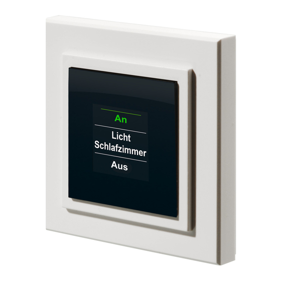
4. Display, Bedienung, Menü 4.1 Display-Aufteilung Das Display ist in 3 Bereiche unterteilt: Der mittlere Bereich (b) gibt Informationen über den Aktor und den Raum. Im obigen Beispiel ist für einen Aktor der Name „Licht“ gewählt worden und der Raum wurde als „Wohnzimmer“ bezeichnet. Die Bezeichnungen können individuell angepasst werden (siehe Abschnitt 8.3). -
Page 8: Allgemeine Bedienung Und Menü
Schaltvorgänge werden über das Display bestätigt. Wenn eine Aktion (z.B. Licht einschalten) über den Wandtaster ausgeführt wird, wird dies während des Sendens zuerst mit einer orangen Darstellung des Textes angezeigt. Erhält der Wandtaster die Rückmeldung vom Aktor, dass das Licht erfolgreich eingeschaltet wurde, wird der Text sogleich grün dargestellt. - Page 9 Das Konfigurations-Menü ist durch einen langen Tastendruck links (a) oder rechts (b) zu öffnen. Details zum Konfigurations-Menü entnehmen Sie bitte dem Abschnitt 8. Kurzer Langer Tastendruck Tastendruck Geräte-/ Menü öffnen Kanalauswahl Geräte-/ Menü öffnen Kanalauswahl Schaltvorgang Schaltvorgang auslösen auslösen Schaltvorgang...
-
Page 10: Allgemeine Systeminformation
4 Sekunden) geöffnet. Nach 60 Sekunden Inaktivität schließt sich das Menü automatisch und der Wandtaster springt zurück in die Bedienebene. 5. Allgemeine Systeminformation zu HomeMatic Dieses Gerät ist Teil des HomeMatic Haussteuer- systems und arbeitet mit dem bidirektionalen BidCoS Funkprotokoll. ®... -
Page 11: Allgemeine Hinweise Zum Funkbetrieb
Alle technischen Dokumente und Updates finden Sie stets aktuell unter www.HomeMatic.com. 6. Allgemeine Hinweise zum Funkbetrieb Die Funk-Übertragung wird auf einem nicht exklusi- ven Übertragungsweg realisiert weshalb Störungen nicht ausgeschlossen werden können. Weitere Störeinflüsse können hervorgerufen werden durch Schaltvorgänge, Elektromotoren oder defekte Elek- trogeräte. -
Page 12: Montage
7. Montage Der Wandtaster ist ein Aufputz-Gerät und kann so- mit überall nachträglich im Haus platziert werden. Sie können zwischen zwei verschiedenen Monta- gearten wählen: (7.1) Montage mit Schrauben, (7.2) Montage mit Klebestreifen 7.1 Montage mit Schrauben Zur Wandmontage gehen Sie wie folgt vor: •... -
Page 13: Montage Mit Klebestreifen
• Zuerst sind die vier Bohrlöcher (a) an der Wand zu markieren. Wenn Sie die Montageplatte dazu an die Wand halten, muss die Aufschrift „top“ auf der sichtbaren Seite oben stehen. • Bohren Sie bei einer Steinwand vier Löcher von 5 mm und verwenden Sie die beiliegenden Dübel. - Page 14 Montageplatte zu befestigen (nicht auf der Seite, auf der das Wort „top“ steht). Ziehen Sie dazu auf einer Seite der Klebestreifen den Schutzfilm ab. Die Laschen der Klebestreifen müssen oben in den ausgesparten Bereichen (b) überstehen. • Ziehen Sie die Schutzfolie der zweiten Klebestreifenseite ab.
-
Page 15: Inbetriebnahme
8. Inbetriebnahme 8.1 Batterien einlegen (wechseln) Der Wandtaster wird mit 3 LR03 (Micro/AAA) Batterien betrieben. • Ziehen Sie den Wandtaster nach oben von der Montageplatte ab. • Auf der Rückseite des Wandtasters sind die Batteriehalterungen zu sehen. • Legen Sie 3 neue LR03-Batterien (Micro/ AAA) polungsrichtig in die Batteriefächer ein. -
Page 16: Anlernen
Ihrer örtlichen Batteriesammelstelle! 8.2 Anlernen Damit Funk-Komponenten miteinander kommunizie- ren können, müssen Sie aneinander angelernt sein. Damit HomeMatic Aktoren mit dem Wandtaster ge- schaltet werden können, gehen Sie wie folgt vor: • Öffnen Sie das Konfigurations- Menü durch einen langen Tastendruck nach links oder rechts (). - Page 17 • Der Anlernvorgang kann nun mit einem Tastendruck nach unten () aktiviert werden. Der Wandtaster sucht dann für 20 Sekunden nach einer anderen HomeMatic Komponente, die ebenfalls im Anlernmodus ist. • Während dieser Zeit ist also auch das anzulernende Gerät in den Anlernmodus zu versetzen.
- Page 18 Abschnitt 8.3. Der Wandtaster verfügt über 10 Kanäle, im Folgenden auch Positionen genannt. An jeden Kanal können bis zu 10 HomeMatic Geräte angelernt werden. Sind mehrere Geräte an einen Kanal angelernt, wird dies als Gruppe be- zeichnet. Ein Schaltvorgang wird für alle Geräte der...
-
Page 19: Namen / Raum Ändern
8.3 Namen / Raum ändern Für jedes am Wandtaster angelernte Gerät bzw. je- den Kanal kann ein Name (z.B. Licht) und ein Raum (z.B. Wohnzimmer) hinterlegt werden. Sie können aus einer Auswahl vorgegebener Bezeichnungen wählen oder einen individuellen Namen mit maximal 12 Zeichen eingeben. - Page 20 Gerät mit Namen „Position“ im Raum „1“. • Bestätigen Sie die Auswahl mit einem Tastendruck nach unten (). • Danach stehen Ihnen neben „Ablernen“ die Punkte „Name ändern“ und „Raum ändern“ zur Verfügung. • Wählen Sie () den Punkt „Name ändern“...
- Page 21 • Sie haben zusätzlich die Möglichkeit einen freien Namen zu hinterlegen bzw. einen vorgegebenen zu ändern, dies ist fortfolgend erklärt. Freie Namensvergabe/Editiermodus: • Mit einem langen Tastendruck (länger als 4 Sekunden) nach links oder rechts () wird der Editiermodus gestartet. •...
-
Page 22: Ablernen
• Mit dem auf Position/Kanal 1 angelernten Aktor wird somit das Deko-Licht im Wohnzimmer geschaltet. 8.4 Ablernen Am Wandtaster angelernte Geräte können auch wie- der abgelernt werden. Das Ablernen erfolgt je Kanal/ Position. Zum Ablernen von Geräten gehen Sie wie folgt vor: •... - Page 23 das Gerät „Deko Licht“ im Raum „Wohnzimmer“ ausgewählt. • Bestätigen Sie Ihre Auswahl mit einem Tastendruck nach unten (). • Wählen Sie anschließend mit Tastendrücken nach links/rechts () den Punkt „Ablernen“ aus. • Bestätigen Sie die Auswahl mit einem Tastendruck nach unten (). •...
-
Page 24: Sprache Auswählen
8.5 Sprache auswählen Im Wandtaster sind zur Bedienung und für Menüs die Sprachen Deutsch und Englisch hinterlegt. Zum ändern der Sprache gehen Sie wie folgt vor: • Öffnen Sie das Konfigurations- Menü durch einen langen Tastendruck nach links oder rechts (). -
Page 25: Werkseinstellungen Wieder Herstellen
im Display. • Bestätigen Sie Ihre Auswahl mit „Speichern“ bzw. „Save“ (). • Zum Verlassen ohne zu speichern drücken Sie „Zurück“ bzw. „Back“ (). 8.6 Werkseinstellungen wieder herstellen Der Wandtaster kann in den Auslieferungszu- stand zurückgesetzt werden. Beim Herstellen der Werkseinstellungen gehen alle gespeicherten Einstellungen und Verknüpfungen verloren. -
Page 26: Display-Standby Zeit Einstellen
• Bestätigen Sie die Auswahl mit einem Tastendruck nach unten (). • Das Wiederherstellen der Werkseinstellungen muss bestätigt werden. • Mit der Auswahl „Nein“ bzw. einem Tastendruck nach oben () beenden Sie den Vorgang. • Mit „Ja“ bzw. einem langen Tastendruck (länger als 4 Sekunden) nach unten () werden die Werkseinstellungen wieder hergestellt. - Page 27 • Öffnen Sie das Konfigurations- Menü durch einen langen Tastendruck nach links oder rechts (). • Danach ist mit Tastendrücken nach links/rechts () der Punkt „Menü, Einstellung“ auszuwählen. • Mit einem Tastendruck nach unten () gelangen Sie in die nächste Menü-Ebene. •...
-
Page 28: Status Rückmeldung
() wird die eingestellte Standby-Zeit gespeichert. 9. Status Rückmeldungen Der Wandtaster als HomeMatic-Komponente über- trägt Daten mittels BidCoS-Protokoll. Dieses Bidi- rektionale Protokoll ermöglicht es, dass sendende Geräte eine Rückmeldung vom empfangenden Gerät erhalten. Wird ein Schaltvorgang am Wandtaster durch einen Tastendruck ausgelöst, wird dies im Display durch... - Page 29 onen (Tastendruck oben und unten) festgelegt. Die folgende Tabelle gibt einen Überblick über die zum Namen/Gerät zugehörigen Schaltfunktionen: Obere Untere Gerät Schaltfunktion Schaltfunktion Aktor Dimmer Fenster Öffnen Schließen Gruppe Jalousie KeyMatic Entriegeln Verriegeln Licht Markise Tür Entriegeln Verriegeln Verschluss Entriegeln Verriegeln WinMatic Öffnen...
-
Page 30: Funktionen Mit Zentrale
11. Funktionen mit Zentrale Im Zusammenspiel mit einer HomeMatic Zentrale sind noch weitere Funktion gegeben, so können z.B. Programme über den Wandtaster gestartet werden. Die Konfiguration muss dann über die Konfigurationsoberfläche der Zentrale geschehen. Über eine Zentrale können alle Namen frei vergeben werden. -
Page 31: Wartung Und Reinigung
Nachdem der Wandtaster an eine Zentrale angelernt wurde, können Geräte nicht mehr direkt am Wandtaster ab- oder angelernt werden. Dies muss über die Bedienoberflä- che der Zentrale geschehen. 12. Wartung und Reinigung Neben einem Batteriewechsel ist das Produkt ist wartungsfrei. Überlassen Sie eine Reparatur einer Fachkraft. - Page 32 Technische Änderungen, die zur Verbesserung die- nen, sind vorbehalten. Entsorgungshinweis Gerät nicht im Hausmüll entsorgen! Elektro- nische Geräte sind entsprechend der Richt- linie über Elektro- und Elektronik-Altgeräte über die örtlichen Sammelstellen für Elektro- nik-Altgeräte zu entsorgen. Das CE-Zeichen ist ein Freiverkehrszeichen, das sich ausschließlich an die Behörden wendet und keine Zusicherung von Eigen- schaften beinhaltet.
- Page 33 English edition 02/2010 Documentation © 2009 eQ-3 Ltd., Hong Kong All rights reserved. This manual may not be reproduced in any format, either in whole or in part, nor may it be duplicated or edited by electronic, mechanical or chemical means, without the written consent of the publisher.
- Page 34 4.2 General operation and menu ... . 39 General system information about HomeMatic ..... 41 General information about radio operation . 42 Mounting .
-
Page 35: Information About This Manual
1 Information about this manual Read this manual carefully before starting to use your HomeMatic components. Keep the manual so you can refer to it at a later date should you need to. If you hand over the device to other persons for use, please hand over the operating manual as well. -
Page 36: Function
3 Function 3.1 General function A wall-mounting pushbutton is used to activate the receivers that have been taught-in to it. It also features a display that is used to show the name of a taught-in device and the room where it is located, and to output status messages relating to radio commands that have been issued. -
Page 37: Scope Of Supply
(A) Wall-mounting pushbutton (B) Mounting plate 3.3 Scope of supply • Wall-mounting pushbutton • Mounting plate • Adhesive strips for wall mounting • 3x LR03 batteries (micro/AAA) • 2x wood screws 3.0 x 30 mm • 2x plugs 5 mm... -
Page 38: Display, Operation, Menu
4. Display, operation, menu 4.1 Display areas The display is divided into 3 areas: The central area (b) provides information about the actuator and the room. In the example above, an actuator has been called “Light” and the room has been named “Living room”. -
Page 39: General Operation And Menu
Switching operations are confirmed on the dis- play. If an action (such as switching on the light) is performed via the wall-mounting pushbutton, the display text will initially be orange to indicate that the associated command is being transmitted. If the wall-mounting pushbutton receives feedback from the actuator confirming that the light has been switched on successfully, the text will immediately... - Page 40 or bottom and holding it down will dim or brighten the light by degrees. The configuration menu can be opened by pressing the button on the left (a) or right (b) and holding it down. For details on the configura- tion menu, please refer to Section 8.
-
Page 41: General System Information About Homematic
5. General information about the HomeMatic system This device is part of the HomeMatic home control system and works with the bi-directional BidCoS ® wireless protocol. All devices are delivered in a stand- ard configuration. -
Page 42: General Information About Radio Operation
You can find the latest versions of all technical documents and the latest updates at www.HomeMatic.com. 6. General information about radio operation Radio transmission is performed on a non-exclusive transmission path, which means that there is a pos- sibility of interference occurring. Interference can also be caused by switching operations, electrical motors or defective electrical devices. -
Page 43: Mounting
7. Mounting The wall-mounting pushbutton is a surface- mounting device, so it can be retrofitted anywhere in the home. You can choose from two different types of mounting: mounting with screws (7.1) or mounting with adhesive strips (7.2). 7.1 Mounting with screws To mount the device on a wall, proceed as follows: •... -
Page 44: Mounting With Adhesive Strips
• First of all, mark four bore hole positions (a) on the wall. When you hold the mounting plate against the wall, the inscription “top” must be visible at the top edge. • If you are working with a stone wall, drill four 5 mm holes and insert the plugs supplied. - Page 45 “top” is printed). To attach the adhesive strips, remove the protective film from one side. The ends of the adhesive strips must protrude from the cut-out areas (b) at the top of the mounting plate. • Pull the protective film off the other side of the adhesive strips.
-
Page 46: Start-Up
When the display has been activated, a cor- responding message will briefly ap- pear. If the device is being operated in conjunction with a HomeMatic central control unit, a service message is sent to the CCU too. -
Page 47: Teaching-In
In order to enable communication between radio components, the devices have to be taught-in to one another. If you want to use the wall-mounting pushbutton to switch HomeMatic actuators, proceed as follows: • Open the configuration menu by pressing and holding down the button on the left or right (). - Page 48 (). For the next 20 seconds the wall-mounting pushbutton will search for another HomeMatic component that is also in teach-in mode. • This means that the device to be taught-in needs to be switched to teach-in mode during this time...
- Page 49 Section 8.3. The wall-mounting pushbutton features 10 channels, also referred to as “positions” in the following. Up to 10 HomeMatic devices can be taught-in to each channel. If several devices have been taught-in to one channel, they are referred to as a group.
-
Page 50: Changing A Name/Room
8.3 Changing a name/room A name (e.g. Light) and a room (e.g. Living room) can be stored for every device taught-in to the wall- mounting pushbutton or for every channel. You can choose from a selection of preset names or enter a customised name with a maximum of 12 characters. - Page 51 • Confirm your selection by pressing the button at the bottom (). • Now you can select either “Teach- out” or the “Change name” or “Change room” items. • Select () the “Change name” or “Change room” item by pressing the button at the bottom () .
- Page 52 Assigning customised names/Edit mode: • Launch edit mode by pressing and holding down the button on the left or right () for more than 4 seconds. • Press the button on the left/ right () to select the 12 digits individually.
-
Page 53: Teaching-Out
8.4 Teaching-out Devices that have been taught-in to the wall- mounting pushbutton can also be taught-out again. Teaching-out is performed separately for each channel/position. To teach-out devices, proceed as follows: • Open the configuration menu by pressing and holding down the button on the left or right (). - Page 54 • Now press the button on the left/right () to select the “Teach-out” item. • Confirm your selection by pressing the button at the bottom (). • A confirmation prompt will then appear. • The teach-out (delete) procedure needs to be confirmed. •...
-
Page 55: Selecting The Language
8.5 Selecting the language The languages English and German are stored in the wall-mounting pushbutton for the purposes of op- eration and menu display. To change the language, proceed as follows: • Open the configuration menu by pressing and holding down the button on the left or right (). -
Page 56: Restoring The Factory Settings
• Confirm your selection by pressing “Save” (). • To exit without saving your changes, press “Back” (). 8.6 Restoring the factory settings The wall-mounting pushbutton can be reset to its initial state. When the factory settings are restored, all saved settings and links are lost. To restore the factory settings, proceed as follows: •... -
Page 57: Setting The Display Standby Time
• Confirm your selection by pressing the button at the bottom (). • You must confirm that you want to restore the factory settings. • Select “No” or press the button at the top () to end the procedure. • Select “Yes” or press and hold down the button at the bottom () for more than 4 seconds to restore the factory settings. - Page 58 • Open the configuration menu by pressing and holding down the button on the left or right (). • Then press the button on the left/ right () to select the “Settings menu” item. • Press the button at the bottom () to access the next menu level.
-
Page 59: Feedback Statuses
9. Feedback statuses As a HomeMatic component, the wall-mounting pushbutton transmits data via the BidCoS protocol. This bi-directional protocol allows transmitting devices to receive feedback from receiving devices. If the wall-mounting pushbutton is pressed to trigger a switching operation, this is indicated on the display by the text turning orange. - Page 60 The table below provides an overview of which switching functions belong to which name/device: Top switching Bottom switching Device function function Actuator Dimmer Window Open Close Group Blinds Open Close KeyMatic Unlock Lock Light Canopy Open Close Door Unlock Lock Lock Unlock Lock...
-
Page 61: Functions With A Central Control Unit
Even more functions are available if you use the wall-mounting pushbutton in conjunction with a HomeMatic central control unit, for example you can start programs from the device. In such cases, the configuration settings must be made via the configuration interface of the central control unit. -
Page 62: Maintenance And Cleaning
Once the wall-mounting pushbutton has been taught-in to a central control unit, it will no longer be possible to teach devices in to or out from the wall-mounting pushbutton direct- ly. This must be done via the central control unit’s user interface. 12. -
Page 63: Technical Characteristics
13. Technical characteristics Open air range: Up to 100 m Display: OLED fully graphical display Power supply: 3x LR03/micro, AAA Degree of protection: IP 20 Housing colour: RAL 9010 pure white with a window surrounded by a black border Dimensions (W x H x D): 83 x 83 x 18 mm Battery life: Approx. - Page 64 Instructions for disposal Do not dispose of the device with regular domestic waste. Electronic equipment must be disposed of at local collection points for waste electronic equipment in compliance with the Waste Electrical and Electronic Equipment Directive. The CE Marking is simply an official symbol relating to the free movement of a product;...
Need help?
Do you have a question about the HM-PB-4Dis-WM and is the answer not in the manual?
Questions and answers