
Related Manuals for HomeMatic HMIP-WRC2


Summary of Contents for HomeMatic HMIP-WRC2
- Page 1 Montage- und Bedienungsanleitung Mounting instruction and operating manual Wandtaster - 2-fach S. 2 Wall-mount Remote Control - p. 27 2-button HMIP-WRC2...
- Page 2 Lieferumfang Anzahl Bezeichnung Homematic IP Wandtaster - 2-fach Wechselrahmen Montageplatte Doppelseitige Klebestreifen Schrauben 3,0 x 30 mm Dübel 5 mm 1,5 V LR03/Micro/AAA Batterien Bedienungsanleitung Dokumentation © 2015 eQ-3 AG, Deutschland Alle Rechte vorbehalten. Ohne schriftliche Zustimmung des Herausgebers darf diese Anleitung auch nicht auszugsweise in...
-
Page 7: Table Of Contents
Inhaltsverzeichnis Hinweise zur Anleitung ...........8 Gefahrenhinweise ............8 Funktion und Geräteübersicht ........10 Allgemeine Systeminformationen ......11 Inbetriebnahme .............. 11 Anlernen ................11 Montage.................13 5.2.1 Klebestreifenmontage..........13 5.2.2 Schraubmontage ............14 5.2.3 Montage in Mehrfachkombinationen ....16 Ecobetrieb ................17 Batterien wechseln ............18 Fehlerbehebung .............19 Schwache Batterie ...............19 Befehl nicht bestätigt ............ -
Page 8: Hinweise Zur Anleitung
Hinweise zur Anleitung Hinweise zur Anleitung Lesen Sie diese Anleitung sorgfältig, bevor Sie Ihre Homematic IP Geräte in Betrieb nehmen. Bewahren Sie die Anleitung zum späteren Nachschlagen auf! Wenn Sie das Gerät anderen Personen zur Nutzung über- lassen, übergeben Sie auch diese Anleitung. - Page 9 Gefahrenhinweise fluss von Feuchtigkeit, Vibrationen, ständiger Sonnen- oder anderer Wärmeeinstrahlung, Kälte und keinen mechanischen Belastungen aus. Das Gerät ist kein Spielzeug! Erlauben Sie Kindern nicht damit zu spielen. Lassen Sie das Verpa- ckungsmaterial nicht achtlos liegen. Plastikfolien/ -tüten, Styroporteile etc. können für Kinder zu einem gefährlichen Spielzeug werden.
-
Page 10: Funktion Und Geräteübersicht
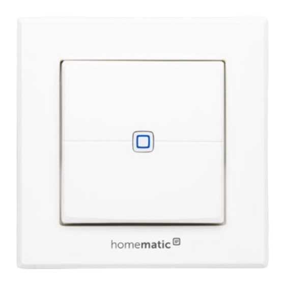
Funktion und Geräteübersicht Funktion und Geräteübersicht Der Homematic IP Wandtaster – 2-fach ist ein flexibel einsetzbarer Funk-Wandtaster mit zwei Kanälen zur zentralen Steuerung von Homematic IP Geräten und Funktionen. Mit nur einem Tastendruck ist es möglich, beispielsweise die Heizung in den Ecobetrieb zu versetzen oder das Licht ein- und auszuschalten. -
Page 11: Allgemeine Systeminformationen
Bitte lesen Sie diesen Abschnitt erst vollständig, bevor Sie mit dem Anlernen beginnen. Richten Sie zunächst Ihren Homematic IP Access Point über die Homematic IP App ein, um weitere Homematic IP Geräte im System nutzen zu kön- nen. Ausführliche Informationen dazu finden Sie... - Page 12 Inbetriebnahme Damit der Wandtaster in Ihr System integriert werden und mit anderen Homematic IP Geräten kommunizieren kann, muss er zunächst an den Homematic IP Access Point angelernt werden. Zum Anlernen des Wandtasters gehen Sie wie folgt vor: • Öffnen Sie die Homematic IP App auf Ihrem Smartphone.
-
Page 13: Montage
Inbetriebnahme • Warten Sie, bis der Anlernvorgang abgeschlossen ist. • Zur Bestätigung eines erfolgreichen Anlernvor- gangs leuchtet die LED grün. Das Gerät ist nun einsatzbereit. • Leuchtet die LED rot, versuchen Sie es erneut. • Wählen Sie die gewünschte Lösung für Ihr Gerät aus. -
Page 14: Klebestreifenmontage
Inbetriebnahme 5.2.1 Klebestreifenmontage Um den zusammengesetzten Wandtaster mit den Klebe- streifen zu montieren, gehen Sie wie folgt vor: • Wählen Sie einen beliebigen Montageort aus. Achten Sie darauf, dass der Montageuntergrund glatt, eben, unbeschädigt, sauber, fett- sowie lö- sungsmittelfrei und nicht zu kühl ist, damit der Klebestreifen langfristig haften kann. - Page 15 Inbetriebnahme Halten Sie die Montageplatte (F) an die ge- • wünschte Montageposition. Achten Sie darauf, dass der Pfeil auf der Vorderseite der Montage- platte nach oben zeigt. • Zeichnen Sie zwei der Bohrlöcher (I) anhand der Montageplatte (diagonal gegenüberliegend) mit einem Stift an der Wand an (s. Abbildung 3). Die Bohrlöcher (J) können für die Montage auf einer Unterputzdose verwendet werden.
-
Page 16: Montage In Mehrfachkombinationen
Inbetriebnahme 5.2.3 Montage in Mehrfachkombinationen Sie können den Wandtaster sowohl mit dem mitgeliefer- ten Rahmen (A), als auch mit Rahmen anderer Hersteller verwenden oder den Taster bzw. die Elektronikeinheit (B) in einen Mehrfachrahmen integrieren. Sie können die Montageplatte (F) flexibel mit Klebestreifen oder Schrauben an der Wand befestigen. -
Page 17: Ecobetrieb
Energie zu sparen. Um die Einstellungen für den Ecobetrieb vorzunehmen, gehen Sie wie folgt vor: • Öffnen Sie die Homematic IP App auf Ihrem Smart- phone. • Tippen Sie auf das Menü-Symbol oben links im Bildschirm und wählen den Menüpunkt „Ecobe- trieb / Wandtaster“... -
Page 18: Batterien Wechseln
Batterien wechseln Batterien wechseln Wird eine leere Batterie in der App bzw. am Gerät ange- zeigt (s. „7.4 Fehlercodes und Blinkfolgen“ auf Seite 21), tauschen Sie die verbrauchten Batterien gegen zwei neue Batterien des Typs LR03/Micro/AAA aus. Beachten Sie da- bei die richtige Polung der Batterien. -
Page 19: Fehlerbehebung
Batterie wieder mehrfach gesendet werden. Bricht beim Senden die Spannung wieder zusammen, wird dies in der Homematic IP App und am Gerät ange- zeigt (s. „7.4 Fehlercodes und Blinkfolgen“ auf Seite 21). Tauschen Sie in diesem Fall die leeren Batterien gegen... -
Page 20: Befehl Nicht Bestätigt
Stunde (also 36 Sekunden in einer Stunde). Die Geräte dürfen bei Erreichen des 1 %-Limits nicht mehr senden, bis diese zeitliche Begrenzung vorüber ist. Gemäß dieser Richtlinie, werden Homematic IP-Geräte zu 100 % nor- menkonform entwickelt und produziert. Im normalen Betrieb wird der Duty Cycle in der Regel nicht erreicht. -
Page 21: Fehlercodes Und Blinkfolgen
Fehlerbehebung Eine Überschreitung des Duty Cycle Limits wird durch dreimal langes rotes Blinken der LED angezeigt und kann sich durch temporär fehlende Funktion des Gerätes äu- ßern. Nach kurzer Zeit (max. 1 Stunde) ist die Funktion des Gerätes wiederhergestellt. Fehlercodes und Blinkfolgen Blinkcode Bedeutung Lösung... - Page 22 Fehlerbehebung Kurzes oranges Anlernmodus Geben Sie die Blinken (alle aktiv letzten vier Ziffern 10 s) der Geräte- Seriennummer zur Bestätigung ein (s. „5.1 Anlernen“ auf Seite 11). 1x langes rotes Vorgang Versuchen Sie es Leuchten fehlgeschla- erneut („7.2 Befehl gen oder Duty nicht bestätigt“...
-
Page 23: Wiederherstellung Der Werkseinstellungen
Wiederherstellung der Werkseinstellungen Wiederherstellung der Werksein- stellungen Die Werksteinstellungen des Gerätes können wiederhergestellt werden. Dabei gehen alle Ein- stellungen verloren. Um die Werkseinstellungen des Wandtasters wiederher- zustellen, gehen Sie wie folgt vor: • Fassen Sie den Taster (B) seitlich an und ziehen Sie ihn aus dem Rahmen heraus (s. -
Page 24: Wartung Und Reinigung
Wartung und Reinigung Wartung und Reinigung Das Gerät ist für Sie bis auf einen eventuell erfor- derlichen Batteriewechsel wartungsfrei. Überlas- sen Sie eine Wartung oder Reparatur einer Fach- kraft. Reinigen Sie das Gerät mit einem weichen, sauberen, trockenen und fusselfreien Tuch. Für die Entfernung von stärkeren Verschmutzungen kann das Tuch leicht mit lauwarmem Wasser angefeuchtet werden. -
Page 25: Technische Daten
Technische Daten Hiermit erklärt die eQ-3 AG, Maiburger Str. 29, 26789 Leer, Deutschland, dass der Funkanlagentyp HmIP-WRC2 der Richtlinie 2014/53/EU entspricht. Der vollständige Text der EU-Konformitätserklärung ist unter der folgen- den Internetadresse verfügbar: www.eq-3.de Technische Daten Geräte-Kurzbezeichnung: HMIP-WRC2 Versorgungsspannung: 2x 1,5 V LR03/Micro/AAA Stromaufnahme: 50 mA max. - Page 26 Technische Daten Entsorgungshinweis Gerät nicht im Hausmüll entsorgen! Elektroni- sche Geräte sind entsprechend der Richtlinie über Elektro- und Elektronik-Altgeräte über die örtlichen Sammelstellen für Elektronik-Altgeräte zu entsorgen. Konformitätshinweis Das CE-Zeichen ist ein Freiverkehrszeichen, das sich ausschließlich an die Behörden wendet und keine Zusicherung von Eigenschaften beinhaltet.
-
Page 27: Package Contents
Package contents Quantity Description Homematic IP Wall-mount Remote Control - 2-button Clip-on frame Mounting plate Double-sided adhesive strips Screws 3.0 x 30 mm Plugs 5 mm 1.5 V LR03/micro/AAA batteries Operating manual Documentation © 2015 eQ-3 AG, Germany All rights reserved. Translation from the original version in Ger- man. - Page 28 Table of contents Information about this manual........29 Hazard information ............29 Function and device overview ........31 General system information ........32 Start-up ................32 Teaching-in ................32 Mounting ................34 5.2.1 Adhesive strip mounting ........34 5.2.2 Screw mounting ............. 35 5.2.3 Installation in multiple combinations ....36 Eco mode ................37 Replacing batteries ............38 Troubleshooting ............
-
Page 29: Information About This Manual
Information about this manual Please read this manual carefully before beginning op- eration with your Homematic IP components. Keep the manual so you can refer to it at a later date if you need to. If you hand over the device to other persons for use, please hand over this manual as well. - Page 30 Hazard information The device may only be operated in dry and dust- free environment and must be protected from the effects of moisture, vibrations, solar or other methods of heat radiation, cold and mechanical loads. The device is not a toy; do not allow children to play with it.
-
Page 31: Function And Device Overview
The Homematic IP Wall-mount Remote Control – 2 buttons offers flexible use via two channels for central control of Homematic IP devices and functions. At just the push of a button, e.g. the eco mode of the heating system can be activated or lights can be swichted on or off. -
Page 32: General System Information
General system information General system information This device is part of the Homematic IP smart home sys- tem and works with the Homematic IP radio protocol. All devices of the system can be configured comfortably and individually with the Homematic IP smartphone app. Al-... - Page 33 Homematic IP Access Point first. To teach-in the wall-mount remote control, please pro- ceed as follows: • Open the Homematic IP app on your smartphone. Select the menu item “Teach-in device”. • To remove the remote control (B) from the frame, •...
-
Page 34: Mounting
Start-up • If the LED lights up red, please try again. • Select the desired solution for your device. • In the app, give the device a name (there is no allocation to a room required for the wall-mount remote control). Mounting Please read this entire section before starting to mount the device. -
Page 35: Screw Mounting
Start-up Make sure that the mounting surface is smooth, solid, non-disturbed, free of dust, grease and sol- vents and not too cold to ensure long-time ad- herence. • Fix the adhesive strips (G) on the back side of the mounting plate (F) in the provided area. You should be able to read the letters on the back side (H) (see figure 2). -
Page 36: Installation In Multiple Combinations
Start-up The bore holes (J) can be used for installation with a flush-mounting box. • Now drill the bore holes. If you are working with a stone wall, drill the marked 5 mm holes and insert the plugs supplied. If you are working with a wooden wall, you can pre-drill 1.5 mm holes to make screws easier to insert. -
Page 37: Eco Mode
Start-up sure that the mounting plate of the push button is seam- lessly aligned to the already fixed mounting plate/retain- ing ring. The wall-mount remote control is designed to fit into frames supplied by the following manufacturers: Manufacturer Frame Berker S.1, B.1, B.3, B.7 glass ELSO System 55, Standard 55, E2, E22,... -
Page 38: Replacing Batteries
“Eco duration via wall-mount remote control”. When leaving home, simply push the Homematic IP Wall- mount Remote Control or slide the switch in the home screen of your app from “Auto” to “Eco” to activate the eco mode. - Page 39 Replacing batteries trol, please proceed as follows: • Once mounted, the remote control can easily be pulled out of the frame (A) or removed from the mounting plate (F). To remove the remote control (B) from the frame, take hold of the sides of the remote control and pull it out (see figure 5).
-
Page 40: Troubleshooting
If the voltage drops too far during transmission, this will be displayed on the device or via the Homematic IP app (see „7.4 Error codes and flashing sequences“ on page 42). In this case, replace the empty batteries by two new bat- teries (see „6 Replacing batteries“... -
Page 41: Duty Cycle
Devices must cease transmission when they reach the 1% limit until this time restriction comes to an end. Homematic IP devices are designed and produced with 100% conformity to this regulation. During normal operation, the duty cycle is not usually reached. -
Page 42: Error Codes And Flashing Sequences
Troubleshooting Error codes and flashing sequences Flashing code Meaning Solution Short orange Radio transmis- Please wait, until flashing sion/attempting transmission has to transmit been confirmed. 1x long green Transmission You can continue lighting confirmed operation. 1x long red Transmission Please try again (s. lighting failed „7.2 Command not... -
Page 43: Restore Factory Settings
Restore factory settings 6x long red Device defec- Please see your app flashing tive for error message or contact your retailer. 1x orange Test display Once the test and 1 x green display has stopped, lighting (after you can continue. inserting bat- teries) Restore factory settings... -
Page 44: Maintenance And Cleaning
Maintenance and cleaning four seconds, until the status LED lights up green. • Release the system button to finish the procedure. The device will perform a restart. Maintenance and cleaning The device does not require you to carry out any maintenance other than replacing the battery when necessary. -
Page 45: General Information About Radio Operation
AG, Maiburger Str. 29, 26789 Leer/Germany hereby declares that the radio equipment type HmIP-WRC2 is in compliance with the Directive 2014/53/EU. The full text of the EU declaration of conformity is available at the fol-... -
Page 46: Technical Specifications
Technical specifications Technical specifications Device short description: HMIP-WRC2 Supply voltage: 2x 1.5 V LR03/micro/AAA Current consumption: 50 mA max. Battery life: 4 years (typ.) Degree of protection: IP20 Ambient temperature: 5 to 35 °C Dimensions (W x H x D):... - Page 47 Technical specifications Information about conformity The CE sign is a free trading sign addressed ex- clusively to the authorities and does not include any warranty of any properties. For technical support, please contact your retailer.
- Page 48 Kostenloser Download der Homematic IP App! Free download of the Homematic IP app! Bevollmächtigter des Herstellers: Manufacturer’s authorised representative: eQ-3 AG Maiburger Straße 29 26789 Leer / GERMANY www.eQ-3.de...
Need help?
Do you have a question about the HMIP-WRC2 and is the answer not in the manual?
Questions and answers