Table of Contents
Advertisement
Quick Links
Advertisement
Table of Contents

Related Manuals for Eaton 9355 Series


Summary of Contents for Eaton 9355 Series
- Page 1 Eaton ® ® 9355 Parallel UPS 10/15 kVA User's Guide p/n: 164201601 Revision E0...
- Page 2 National Fire Protection Association, Inc. ERIFLEX and FLEXIBAR are registered trademark of Erico International Corporation. All other trademarks are property of their respective companies. ©Copyright 2005-2019 Eaton, Raleigh, NC, USA. All rights reserved. No part of this document may be reproduced in any way without the express written approval of Eaton.
- Page 3 5.10 Third Party Intellectual Property Rights. The Firmware may contain components transfer the Firmware directly to a third party only in connection with the sale of the Eaton (including open source software components) that are owned by third parties (“Third Party product in which it is installed.
-
Page 5: Table Of Contents
6 6 O O p p e e r r a a t t i i o o n n ............................................................4 4 9 9 6.1 Control Panel Functions ..........................49 6.1.1 Changing the Language........................49 6.1.2 Display Functions ..........................49 6.1.3 User Settings............................. 50 Eaton 9355 Parallel UPS (10/15 kVA) User's Guide 164201601—Rev E0... - Page 6 8 8 W W a a r r r r a a n n t t y y ............................................................6 6 1 1 Eaton 9355 Parallel UPS (10/15 kVA) User's Guide 164201601—Rev E0...
- Page 7 L L i i s s t t o o f f F F i i g g u u r r e e s s Figure 1. The Eaton 9355 UPS and EBM (3-High Cabinets Shown) ................ 1 Figure 2.
- Page 8 Version 2 Bypass Cabinet Bypass Wiring Diagram – with MIS..............47 Figure 44. Version 2 Tie Cabinet Parallel UPS Schematic..................48 Figure 45. Eaton 9355 UPS Control Panel ......................49 viii Eaton 9355 Parallel UPS (10/15 kVA) User's Guide 164201601—Rev E0...
- Page 9 UPS Cabinet Weights ........................10 Table 3. UPS Cabinet Clearances ......................... 11 Table 4. Eaton 9355 10–15 kVA Parallel UPS: Recommended Terminal Block Wiring ..........12 Table 5. Menu Map for Display Functions ...................... 50 Table 6. User Settings..........................51...
-
Page 10: List Of Tables
List of Tables Eaton 9355 Parallel UPS (10/15 kVA) User's Guide 164201601—Rev E0... -
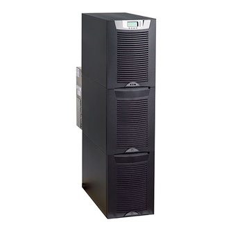
Page 11: Figure 1. The Eaton 9355 Ups And Ebm (3-High Cabinets Shown)
Chapter 8 Warranty for details. This service is offered as part of the sales contract for the UPS. Contact an Eaton service representative in advance (a minimum two-week notice is required) to reserve a preferred startup date. Figure 1. The Eaton 9355 UPS and EBM (3-High Cabinets Shown) - Page 12 U U s s i i n n g g T T h h i i s s M M a a n n u u a a l l This manual describes how to install and operate the Eaton 9355 UPS. Read and understand the procedures described in this manual to ensure trouble-free installation and operation.
-
Page 13: For More Information
F F o o r r M M o o r r e e I I n n f f o o r r m m a a t t i i o o n n Refer to the Eaton 9355 UPS 10/15 kVA User’s Guide for the following additional information: •... - Page 14 E E q q u u i i p p m m e e n n t t R R e e g g i i s s t t r r a a t t i i o o n n Please visit www.eaton.com/pq/register to register your new Eaton UPS / Eaton UPS Accessory. Model Number: Serial Number:...
- Page 15 • Proper disposal of batteries is required. Refer to your local codes for disposal requirements. • Never dispose of batteries in a fire. Batteries may explode when exposed to flame. Eaton 9355 Parallel UPS (10/15 kVA) User's Guide 164201601—Rev E0...
- Page 16 Une mise au rebut réglementaire des batteries est obligatoire. Consulter les règlements en vigueur dans votre localité. • Ne jamais jeter les batteries au feu. L'exposition aux flammes risque de les faire exploser. Eaton 9355 Parallel UPS (10/15 kVA) User's Guide 164201601—Rev E0...
- Page 17 Es necesario desechar las baterías de un modo adecuado. Consulte las normas locales para conocer los requisitos pertinentes. • Nunca deseche las baterías en el fuego. Las baterías pueden explotar si se las expone a la llama. Eaton 9355 Parallel UPS (10/15 kVA) User's Guide 164201601—Rev E0...
-
Page 18: Safety Warnings
Safety Warnings Eaton 9355 Parallel UPS (10/15 kVA) User's Guide 164201601—Rev E0... - Page 19 The system must be installed on a level floor suitable for computer or electronic equipment. • The system must be operated at an altitude no higher than 1500m (5000 ft) without derating. For additional assistance with high altitude operation, contact an Eaton service representative (see paragraph 1.5 Getting Help).
-
Page 20: Table 1. Air Conditioning Or Ventilation Requirements During Full Load Operation
Maximum Weight lb/in (kg/cm Eaton 9355 UPS 2-High UPS 381 lb (173 kg) 95 (6.7) 3-High UPS-32 587 lb (266 kg) 147 (10.3) 3-High UPS-64 619 lb (281 kg) 155 (10.9) Eaton 9355 Parallel UPS (10/15 kVA) User's Guide 164201601—Rev E0... -
Page 21: Table 3. Ups Cabinet Clearances
From Right of Cabinet Refer to local codes for right side service access [minimum 36" (91.4 cm)] For UPS cabinet and Extended Battery Module cabinet dimensions and center of gravity, see Eaton 9355 10/15 kVA UPS User’s Guide. 3 3 . . 3 3... -
Page 22: Table 4. Eaton 9355 10–15 Kva Parallel Ups: Recommended Terminal Block Wiring
UPS Installation Plan and Unpacking Table 4. Eaton 9355 10–15 kVA Parallel UPS: Recommended Terminal Block Wiring Feeder Circuit Tighten- Conduit Size 2, 3 L1, L2, L3, Ground Breaker Wire (Number of N Wire Wire Torque Voltage Rating Conduits) Model... -
Page 23: Three-High Cabinets Or Two-High Ebms
4 4 . . 2 2 . . 1 1 T T h h r r e e e e - - H H i i g g h h C C a a b b i i n n e e t t s s o o r r T T w w o o - - H H i i g g h h E E B B M M s s To remove a three-high cabinet or a two-high EBM from the shipping pallet: Remove the two M10 bolts securing the stabilizing bracket to the pallet (see Figure Eaton 9355 Parallel UPS (10/15 kVA) User's Guide 164201601—Rev E0... -
Page 24: Figure 2. Removing The Stabilizing Bracket Bolts
Hold the back of the cabinet so that the bolts can be removed easily without the cabinet rolling backward. Remove the two M10 bolts securing the front shipping bracket and remove the bracket. If needed, adjust the leveling feet to release the bracket. Eaton 9355 Parallel UPS (10/15 kVA) User's Guide 164201601—Rev E0... -
Page 25: Figure 3. Removing The Brackets And Shipping Pad
Slowly roll the cabinet toward the rear of the pallet. Once the pallet tilts, continue rolling the cabinet down the pallet until the cabinet touches the floor (see Figure If needed, adjust the leveling feet so that the cabinet rolls freely. Eaton 9355 Parallel UPS (10/15 kVA) User's Guide 164201601—Rev E0... -
Page 26: Figure 4. Unloading The Cabinet
Remove the M10 bolt securing the vertical bracket to the pallet (see Figure Remove and retain the three M4 screws securing the vertical bracket to the UPS. Remove the vertical bracket. Eaton 9355 Parallel UPS (10/15 kVA) User's Guide 164201601—Rev E0... -
Page 27: Figure 6. Removing The Vertical Bracket
Remove the three M10 bolts securing the rear shipping pad to the pallet and remove the shipping pad (see Figure NOTE Hold the back of the cabinet so that the bolts can be removed easily without the cabinet rolling backward. Eaton 9355 Parallel UPS (10/15 kVA) User's Guide 164201601—Rev E0... -
Page 28: Figure 8. Removing The Front Shipping Bracket And Shipping Pad
10. Slowly roll the cabinet toward the rear of the pallet. Once the pallet tilts, continue rolling the cabinet down the pallet until the cabinet touches the floor (see Figure If needed, adjust the leveling feet so that the cabinet rolls freely. Eaton 9355 Parallel UPS (10/15 kVA) User's Guide 164201601—Rev E0... -
Page 29: Figure 9. Unloading The Cabinet
E E x x t t e e r r n n a a l l A A C C P P o o w w e e r r W W i i r r i i n n g g I I n n s s t t a a l l l l a a t t i i o o n n You are now ready to install the Eaton 9355 UPS. Select one of the following installation options according to your UPS configuration: •... -
Page 30: Figure 11. Version 1 Parallel Tie Cabinet Front Cover
NOTE To accommodate the feature of easy system expandability, it is recommended that initial installation of the Eaton 9355 UPS contain wiring to support the maximum capacity of the UPS cabinet. Switch off utility power to the distribution point where the parallel tie cabinet and UPSs will be connected. -
Page 31: Figure 12. Version 1 Internal Cover
10. Verify that each UPS battery circuit breaker is in the OFF position (see Figure 14). 11. From each UPS, remove the UPS wiring access cover and one of the conduit landing plates and retain. Eaton 9355 Parallel UPS (10/15 kVA) User's Guide 164201601—Rev E0... -
Page 32: Figure 14. Ups Rear View (3-High Shown)
Input neutral must be wired for proper operation. Failure to connect an input neutral will void the warranty. If the optional input transformer is installed, an input neutral is not required. NOTE 2 The Eaton 9355 UPS is a single-feed UPS only. Eaton 9355 Parallel UPS (10/15 kVA) User's Guide 164201601—Rev E0... -
Page 33: Figure 15. Ups Terminal Block (3-High Shown)
Connect the black and the red wire to TB2 on the UPS. Cap the blue wire. NOTE The maintenance bypass contacts are normally-open. To ensure proper bypass operation, DO NOT use the blue wire (it is normally-closed). Eaton 9355 Parallel UPS (10/15 kVA) User's Guide 164201601—Rev E0... -
Page 34: Figure 17. Version 1 Load Connections
Figure 17. Version 1 Load Connections Maintenance Bypass Wiring to UPS TB2 Ground Neutral Line 1 Line 2 Line 3 19. Wire the AC input to the bypass breaker (see Figure 18). Eaton 9355 Parallel UPS (10/15 kVA) User's Guide 164201601—Rev E0... -
Page 35: Figure 18. Version 1 Bypass Ac Input Wiring
To hardwire the parallel system: Verify that the electrical connections to the installation site have been properly installed. A wall-mounted, user–supplied, readily–accessible disconnection device must be incorporated in the input wiring. Eaton 9355 Parallel UPS (10/15 kVA) User's Guide 164201601—Rev E0... -
Page 36: Figure 19. Version 2 Parallel Tie Cabinet Front Door And Cover
NOTE To accommodate the feature of easy system expandability, it is recommended that initial installation of the Eaton 9355 UPS contain wiring to support the maximum capacity of the UPS cabinet. Switch off utility power to the distribution point where the parallel tie cabinet and UPSs will be connected. -
Page 37: Figure 20. Version 2 Parallel Tie Cabinet Front Cover Open
UPS System Installation Figure 20. Version 2 Parallel Tie Cabinet Front Cover Open Internal Cover Front Cover Remove the internal cover to gain access to the breakers (see Figure 21). Eaton 9355 Parallel UPS (10/15 kVA) User's Guide 164201601—Rev E0... -
Page 38: Figure 21. Version 2 Parallel Tie Cabinet Internal Cover
® Verify that the parallel bypass breaker is in the OFF position (see Figure 22). 10. Mount the parallel tie cabinet to the wall and install the conduit. Eaton 9355 Parallel UPS (10/15 kVA) User's Guide 164201601—Rev E0... -
Page 39: Figure 22. Version 2 Parallel Tie Cabinet Bypass Breaker
12. From each UPS, remove the UPS wiring access cover and one of the conduit landing plates and retain. 13. Punch two holes in the conduit landing plate for the input and output conduit using a Greenlee punch or similar device. Eaton 9355 Parallel UPS (10/15 kVA) User's Guide 164201601—Rev E0... -
Page 40: Figure 23. Ups Rear View (3-High Shown)
Input neutral must be wired for proper operation. Failure to connect an input neutral will void the warranty. If the optional input transformer is installed, an input neutral is not required. NOTE 2 The Eaton 9355 UPS is a single-feed UPS only. Eaton 9355 Parallel UPS (10/15 kVA) User's Guide 164201601—Rev E0... -
Page 41: Figure 24. Ups Terminal Block (3-High Shown)
UPS System Installation Figure 24. UPS Terminal Block (3-High Shown) Maintenance Bypass Contacts Ground 15. Hardwire the output terminations from the UPS to the parallel tie cabinet (see Figure 25). Eaton 9355 Parallel UPS (10/15 kVA) User's Guide 164201601—Rev E0... -
Page 42: Figure 25. Version 2 Tie Cabinet Ups Output To Parallel Tie Wiring
DO NOT use the blue wire (it is normally-closed). 18. Replace the UPS wiring access cover and conduit landing plate. 19. Repeat Step 13 through Step 18 for each UPS. Eaton 9355 Parallel UPS (10/15 kVA) User's Guide 164201601—Rev E0... -
Page 43: Figure 26. Version 2 Tie Cabinet Load Connections
Figure 26. Version 2 Tie Cabinet Load Connections Line 1 Line 2 Line 3 Neutral Ground Maintenance Bypass Wiring to UPS TB2 20. Wire the AC input to the bypass breaker (see Figure 27). Eaton 9355 Parallel UPS (10/15 kVA) User's Guide 164201601—Rev E0... -
Page 44: Installing Options
This section describes the Powerware Hot Sync CAN Bridge Card. For other options, such as additional X-Slot cards, LanSafe Power Management Software, remote emergency power-off (REPO), relay output contacts, or programmable signal inputs, refer to the Eaton 9355 UPS (10/ 15 kVA) User's Guide. -
Page 45: Powerware Hot Sync Can Bridge Card
Remove the front covers of all cabinets, starting with the top cabinet. Press and release the handle latch at the bottom of each cover and then lift the cover up and off the cabinet (see Figure 30). Eaton 9355 Parallel UPS (10/15 kVA) User's Guide 164201601—Rev E0... -
Page 46: Figure 30. Removing The Front Covers
UPS, the remaining UPS transfers the load to bypass instead of supporting the load. Verify all CAN Bridge Card wiring is correct for proper operation NOTE Signal Input 2 can still be used for building alarms; it is automatically rerouted to the CAN Bridge Card. Eaton 9355 Parallel UPS (10/15 kVA) User's Guide 164201601—Rev E0... -
Page 47: Figure 31. Can Bridge Card Wiring
On the bottom cover (and also the middle cover if 3-high), remove a knockout tab in the top edge of the cover for each cable: With wire cutters, cut either side of the tab and twist down to remove the tab (see Figure 32). Eaton 9355 Parallel UPS (10/15 kVA) User's Guide 164201601—Rev E0... -
Page 48: Stabilizing The Cabinet
UPS installation. NOTE After UPS startup, ensure maximum battery runtime by configuring the UPS for the correct number of EBMs (see paragraph 6.3 Configuring the UPS for EBMs). Eaton 9355 Parallel UPS (10/15 kVA) User's Guide 164201601—Rev E0... -
Page 49: Extended Battery Module Installation
4 4 . . 3 3 . . 4 4 S S t t a a b b i i l l i i z z i i n n g g t t h h e e C C a a b b i i n n e e t t NOTE 1 For seismic installations, you MUST order and install an Eaton 9355 UPS seismic kit; do not use the following instructions. -
Page 50: Figure 35. Stabilizing Bracket With One Cabinet
UPS System Installation Figure 35. Stabilizing Bracket with One Cabinet Figure 36. Stabilizing Bracket with Two Cabinets Eaton 9355 Parallel UPS (10/15 kVA) User's Guide 164201601—Rev E0... -
Page 51: Figure 37. Stabilizing Bracket With Three Cabinets
Plug the EBM cable into the UPS battery connector. If additional EBMs are installed, plug the EBM cable of the second cabinet into the battery connector on the first EBM. Repeat for each additional EBM. Eaton 9355 Parallel UPS (10/15 kVA) User's Guide 164201601—Rev E0... -
Page 52: Figure 38. Typical Ebm Installation (2-High Cabinets Shown)
UPS. NOTE After UPS startup, ensure maximum battery runtime by configuring the UPS for the correct number of EBMs (see paragraph 6.3 Configuring the UPS for EBMs). Eaton 9355 Parallel UPS (10/15 kVA) User's Guide 164201601—Rev E0... -
Page 53: Figure 39. Front Ground Strap Installation (2-High Cabinets Shown)
UPS System Installation Figure 39. Front Ground Strap Installation (2-High Cabinets Shown) Front Ground Strap Eaton 9355 Parallel UPS (10/15 kVA) User's Guide 164201601—Rev E0... -
Page 54: Ups System Installation
UPS System Installation Eaton 9355 Parallel UPS (10/15 kVA) User's Guide 164201601—Rev E0... -
Page 55: Figure 40. Version 1 Tie Cabinet Parallel Wiring Diagram
Auxiliary Contacts Blue Wire (closed when breaker is open) 225A Bypass Input 80A (4X) LOAD From UPS 1 Output From UPS 2 Output From UPS 3 Output From UPS 4 Output Eaton 9355 Parallel UPS (10/15 kVA) User's Guide 164201601—Rev E0... -
Page 56: Figure 41. Version 1 Tie Cabinet Parallel Ups Schematic
UPS Wiring Diagram Schematics Figure 41. Version 1 Tie Cabinet Parallel UPS Schematic Eaton 9355 Parallel UPS (10/15 kVA) User's Guide 164201601—Rev E0... -
Page 57: Figure 42. Version 2 Tie Cabinet Parallel Wiring Diagram - Without Maintenance Isolation Switch (Mis)
Wires Auxiliary Contacts (common) Blue Wires (closed when breaker is open) 225A Bypass Input 110A (4X) 80A (4X) LOAD From UPS 1 Output 225A Not Used Not Used Not Used Eaton 9355 Parallel UPS (10/15 kVA) User's Guide 164201601—Rev E0... -
Page 58: Figure 44. Version 2 Tie Cabinet Parallel Ups Schematic
UPS Wiring Diagram Schematics Figure 44. Version 2 Tie Cabinet Parallel UPS Schematic Eaton 9355 Parallel UPS (10/15 kVA) User's Guide 164201601—Rev E0... -
Page 59: Figure 45. Eaton 9355 Ups Control Panel
C C h h a a p p t t e e r r 6 6 O O p p e e r r a a t t i i o o n n This chapter contains information on how to use the Eaton 9355 UPS, including front panel operation, UPS Removing the Existing Power Cords startup and shutdown, and configuring the UPS for Extended Battery Modules (EBMs). -
Page 60: User Settings
As the default or after 15 minutes of inactivity, the LCD displays the As the default or after 15 minutes of inactivity, the LCD displays the selectable startup screen. The default is the Eaton logo and can be selectable startup screen. The default is the Eaton logo and r after 15 minutes of inactivity, the LCD displays the selectable startup screen. -
Page 61: Table 6. User Settings
Automatic Battery Tests Enabled Enabled/Disabled Enabled automatically runs the battery test once a month. Full Power Battery Test Enabled/Disabled Enabled Number of Battery Strings 0 through 22 2 strings for UPS-32 models Eaton 9355 Parallel UPS (10/15 kVA) User's Guide 164201601—Rev E0... -
Page 62: Initial Startup
See Chapter 8 Warranty for details. This service is offered as part of the sales contract for the UPS. Contact an Eaton service representative in advance (a minimum two-week notice is required) to reserve a preferred startup date. WARNING Only qualified service personnel (such as a licensed electrician) should perform the UPS installation. - Page 63 Only qualified service personnel (such as a licensed electrician) should perform the UPS installation. Initial startup must be performed by an authorized Eaton Customer Service Engineer. Risk of electrical shock. Verify that UPS installation has been carried out correctly and the UPS ground has been connected.
- Page 64 As the default or after 15 minutes of inactivity, the LCD displays the screen. screen. Display Functions selectable startup screen. The default is the Eaton logo and can be to ensure consistent runtimes. selectable startup screen. The default is the Eaton logo and can be Display Functions changed to the Mimic screen in the User Settings menu.
- Page 65 As the default or after 15 minutes of inactivity, the LCD displays the p screen. The default is the Eaton logo and can be selectable startup screen. The default is the Eaton logo and can be UPS + 3 EBMs Mimic screen in the User Settings menu.
-
Page 66: Restarting The Parallel System
As the default or after 15 minutes of inactivity, the LCD displays the selectable startup screen. The default is the selectable startup screen. The default is the Eaton logo and can be changed to the Mimic screen in the User Se... -
Page 67: Parallel Bypass
15 minutes of inactivity, the LCD displays the Verify that the maintenance isolation breaker (if present) on the Tie artup screen. The default is the Eaton logo and can be The UPS is now powering the load in Bypass mode. - Page 68 Operation Eaton 9355 Parallel UPS (10/15 kVA) User's Guide 164201601—Rev E0...
-
Page 69: Typical Alarms And Conditions
C C h h a a p p t t e e r r 7 7 T T r r o o u u b b l l e e s s h h o o o o t t i i n n g g OPERATION The Eaton 9355 UPS is designed for durable, automatic operation and also alerts you whenever potential operating problems may occur. Usually the alarms shown by the control panel do not mean that the output power is affected. - Page 70 Display Functions Reset the REPO switch and restart the UPS. Verify that selectable startup screen. The default is the Eaton logo and can be selectable startup screen. The default is the Eaton logo and can be switch is active or the REPO connector is the REPO connector is present.
- Page 71 C C h h a a p p t t e e r r 8 8 W W a a r r r r a a n n t t y y For warranty information, please refer to the Resources link on our website, www.eaton.com/9355.
- Page 72 164201601E0 164201601 E0...
Need help?
Do you have a question about the 9355 Series and is the answer not in the manual?
Questions and answers