Eaton 9355 User Manual
10/15 kva
Hide thumbs
Also See for 9355:
- Installation manual ,
- User manual (120 pages) ,
- Installation and operation manual (100 pages)
Table of Contents
Advertisement
Advertisement
Table of Contents

Related Manuals for Eaton 9355


Summary of Contents for Eaton 9355
- Page 1 Eaton ® ® 9355 UPS 10/15 kVA User’s Guide p/n: 164201594 Revision H0...
- Page 2 National Fire Protection Association, Inc. ERIFLEX and FLEXIBAR are registered trademark of Erico International Corporation. All other trademarks are property of their respective companies. ©Copyright 2005-2019 Eaton, Raleigh, NC, USA. All rights reserved. No part of this document may be reproduced in any way without the express written approval of Eaton.
- Page 3 5.10 Third Party Intellectual Property Rights. The Firmware may contain components transfer the Firmware directly to a third party only in connection with the sale of the Eaton (including open source software components) that are owned by third parties (“Third Party product in which it is installed.
-
Page 5: Table Of Contents
4.3.2 UPS and UPS with Input Isolation Transformer Power Wiring Installation............38 4.3.3 UPS with a Version 1 Wall-Mounted Bypass Switch ................... 41 4.3.4 UPS with a Version 2 Wall-Mounted Bypass Switch ................... 47 Eaton 9355 UPS (10/15 kVA) User’s Guide 164201594—Rev H0... - Page 6 8 8 U U P P S S M M a a i i n n t t e e n n a a n n c c e e ....................................................... . 9 9 9 9 8.1 UPS and Battery Care ..........................99 8.1.1 Storing the UPS and Batteries ....................... 99 8.2 When to Replace Batteries ......................... 99 8.3 Recycling the Used Battery or UPS....................... 99 Eaton 9355 UPS (10/15 kVA) User’s Guide 164201594—Rev H0...
- Page 7 1 1 1 1 W W a a r r r r a a n n t t y y ..........................................................1 1 0 0 7 7 Eaton 9355 UPS (10/15 kVA) User’s Guide 164201594—Rev H0...
- Page 8 Table of Contents viii Eaton 9355 UPS (10/15 kVA) User’s Guide 164201594—Rev H0...
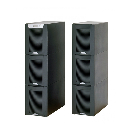
- Page 9 L L i i s s t t o o f f F F i i g g u u r r e e s s Figure 1. The Eaton 9355 UPS and EBM (3-High Cabinets Shown) ................ 1 Figure 2.
- Page 10 RMP Top Internal View........................82 Figure 70. Industrial Relay Card ........................83 Figure 71. External Control Terminal Connections ..................... 84 Figure 72. Eaton 9355 UPS Control Panel ......................87 Figure 73. Maintenance Bypass Switch......................94 Eaton 9355 UPS (10/15 kVA) User’s Guide 164201594—Rev H0...
- Page 11 Table 4. Eaton 9355 10–15 kVA UPS: Recommended Terminal Block Wiring ............25 Table 5. Eaton 9355 10–15 kVA UPS with Version 1 Wall-Mounted Bypass Switch: Recommended Terminal Block Wiring ............................27 Table 6. Eaton 9355 10–15 kVA UPS with Version 2 Wall-Mounted Bypass Switch: Recommended Terminal Block Wiring ............................
-
Page 12: List Of Tables
List of Tables Eaton 9355 UPS (10/15 kVA) User’s Guide 164201594—Rev H0... - Page 13 UPS supplies clean, consistent power that sensitive electronic equipment requires for reliable operation. During brownouts, blackouts, and other power interruptions, batteries provide emergency power to safeguard operation. With the Eaton 9355 UPS, you can safely eliminate the effects of electrical line disturbances and guard the integrity of your systems and equipment. Figure 1 shows the Eaton 9355 UPS and an optional Extended Battery Module (EBM).
-
Page 14: Ups Standard Features
72 hours. Twenty-four hours into the float period, a series of battery tests are performed to check the battery health. The float level charge continues after a successful test. Eaton 9355 UPS (10/15 kVA) User’s Guide 164201594—Rev H0... -
Page 15: Extended Battery Module (Ebm)
1 1 . . 2 2 . . 2 2 P P a a r r a a l l l l e e l l S S y y s s t t e e m m Up to four 9355 UPSs can be paralleled for either redundancy or extra capacity using Eaton’s patented Powerware Hot Sync paralleling technology. -
Page 16: Battery System
1 1 . . 3 3 . . 1 1 B B a a t t t t e e r r y y C C o o n n f f i i g g u u r r a a t t i i o o n n s s The 9355 UPS battery system can be internal to the UPS cabinet, an Extended Battery Module/s (EBM)s, or a combination of both. -
Page 17: For More Information
(WEEE) in the trash. For proper disposal, contact your local recycling/reuse or hazardous waste center. ON - Indicates that the switch is in the ON position. OFF - Indicates that the switch is in the OFF position. PHASE - The word “phase.” Eaton 9355 UPS (10/15 kVA) User’s Guide 164201594—Rev H0... - Page 18 F F o o r r M M o o r r e e I I n n f f o o r r m m a a t t i i o o n n Refer to the Eaton 9355 Parallel UPS 10/15 kVA User’s Guide for the following additional information: •...
- Page 19 Keep unauthorized personnel away from batteries. • Proper disposal of batteries is required. Refer to your local codes for disposal requirements. • Never dispose of batteries in a fire. Batteries may explode when exposed to flame. Eaton 9355 UPS (10/15 kVA) User’s Guide 164201594—Rev H0...
- Page 20 Une mise au rebut réglementaire des batteries est obligatoire. Consulter les règlements en vigueur dans votre localité. • Ne jamais jeter les batteries au feu. L'exposition aux flammes risque de les faire exploser. Eaton 9355 UPS (10/15 kVA) User’s Guide 164201594—Rev H0...
- Page 21 Es necesario desechar las baterías de un modo adecuado. Consulte las normas locales para conocer los requisitos pertinentes. • Nunca deseche las baterías en el fuego. Las baterías pueden explotar si se las expone a la llama. Eaton 9355 UPS (10/15 kVA) User’s Guide 164201594—Rev H0...
-
Page 22: Safety Warnings
Safety Warnings Eaton 9355 UPS (10/15 kVA) User’s Guide 164201594—Rev H0... -
Page 23: Getting Help
1.8 Getting Help). • The environmental requirements specified below are for the air at the intake ports of the 9355 UPS, and are the maximum, not to exceed, ratings. – There shall be at least a 1.8°F (1.0°C) difference between the dry bulb temperature and the wet bulb temperature, at all times, to maintain a non-condensing environment. - Page 24 Standard Model Floor Loadings (2-High/3-High Cabinets) Point Loading Maximum Weight lb/in (kg/cm Eaton 9355 UPS 2-High UPS 381 lb (173 kg) 95 (6.7) 3-High UPS-32 587 lb (266 kg) 147 (10.3) Eaton 9355 UPS (10/15 kVA) User’s Guide 164201594—Rev H0...
- Page 25 6" (15.2 cm) without PDM installed; with PDM installed, clearance determined by customer-supplied mating plug From Back of Cabinet From Right of Cabinet Refer to local codes for right side service access [minimum 36" (91.4 cm)] Eaton 9355 UPS (10/15 kVA) User’s Guide 164201594—Rev H0...
- Page 26 UPS Installation Plan and Unpacking Figure 2. UPS Cabinet Dimensions (2-High Front and Right Side Views) Dimensions are in millimeters [inches] Eaton 9355 UPS (10/15 kVA) User’s Guide 164201594—Rev H0...
- Page 27 UPS Installation Plan and Unpacking Figure 3. Extended Battery Module Dimensions (2-High Front and Right Side Views) Dimensions are in millimeters [inches] Eaton 9355 UPS (10/15 kVA) User’s Guide 164201594—Rev H0...
- Page 28 UPS Installation Plan and Unpacking Figure 4. UPS Cabinet Dimensions (3-High Front and Right Side Views) Dimensions are in millimeters [inches] Eaton 9355 UPS (10/15 kVA) User’s Guide 164201594—Rev H0...
- Page 29 UPS Installation Plan and Unpacking Figure 5. Extended Battery Module Dimensions (3-High Front and Right Side Views) Dimensions are in millimeters [inches] Eaton 9355 UPS (10/15 kVA) User’s Guide 164201594—Rev H0...
- Page 30 UPS Installation Plan and Unpacking Figure 6. UPS Cabinet Dimensions (2 or 3-High Top and Bottom Views) Dimensions are in millimeters [inches] Eaton 9355 UPS (10/15 kVA) User’s Guide 164201594—Rev H0...
- Page 31 UPS Installation Plan and Unpacking Figure 7. Extended Battery Module Dimensions (2 or 3-High Top and Bottom Views) Dimensions are in millimeters [inches] Eaton 9355 UPS (10/15 kVA) User’s Guide 164201594—Rev H0...
- Page 32 Dimensions are in millimeters [inches] Dimensions mm [in] Figure Weight Weight and Center of Gravity kg [lb] Eaton 9355 8–15 kVA UPS 2- 81 [3.2] 452 [17.8] 406 [16.0] 169 [373] High Eaton 9355 UPS (10/15 kVA) User’s Guide 164201594—Rev H0...
- Page 33 Dimensions are in millimeters [inches] Dimensions mm [in] Figure Weight Weight and Center of Gravity kg [lb] Eaton 9355 Extended Battery 81 [3.2] 452 [17.8] 406 [16.0] 218 [480] Module 2-High Eaton 9355 UPS (10/15 kVA) User’s Guide 164201594—Rev H0...
- Page 34 Dimensions are in millimeters [inches] Dimensions mm [in] Figure Weight Weight and Center of Gravity kg [lb] Eaton 9355 8–15 kVA UPS 3- 81 [3.2] 452 [17.8] 610 [24.0] 276 [609] High Eaton 9355 UPS (10/15 kVA) User’s Guide 164201594—Rev H0...
- Page 35 Dimensions are in millimeters [inches] Dimensions mm [in] Figure Weight Weight and Center of Gravity kg [lb] Eaton 9355 Extended Battery 81 [3.2] 452 [17.8] 610 [24.0] 276 [609] Module 3-High Eaton 9355 UPS (10/15 kVA) User’s Guide 164201594—Rev H0...
- Page 36 Input neutral must be wired for proper operation. Failure to connect an input neutral will void the warranty. If the optional input transformer is installed, an input neutral is not required. • The Eaton 9355 UPS is a single-feed UPS only. Eaton 9355 UPS (10/15 kVA) User’s Guide 164201594—Rev H0...
- Page 37 UPS Installation Plan and Unpacking Table 4. Eaton 9355 10–15 kVA UPS: Recommended Terminal Block Wiring Feeder Circuit Tighten- Conduit Size 2, 3 L1, L2, L3, Ground Breaker Wire (Number of N Wire Wire Torque Voltage Rating Conduits) Model Function...
- Page 38 UPS Installation Plan and Unpacking Table 4. Eaton 9355 10–15 kVA UPS: Recommended Terminal Block Wiring (Continued) Feeder Circuit Tighten- Conduit Size 2, 3 L1, L2, L3, Ground Breaker Wire (Number of N Wire Wire Torque Voltage Rating Conduits) Model...
- Page 39 UPS Installation Plan and Unpacking Table 5. Eaton 9355 10–15 kVA UPS with Version 1 Wall-Mounted Bypass Switch: Recommended Terminal Block Wiring Feeder L1, L2, Circuit Tighten- Conduit Size 2, 3 Wire Ground Breaker (Number of Func- N Wire Wire...
- Page 40 UPS Installation Plan and Unpacking Table 6. Eaton 9355 10–15 kVA UPS with Version 2 Wall-Mounted Bypass Switch: Recommended Terminal Block Wiring Feeder L1, L2, Circuit Tighten- Conduit Size 2, 3 Wire Ground Breaker (Number of Func- N Wire Wire...
- Page 41 NOTE Check the battery recharge date on the packaging label. If the date has expired and the batteries were never recharged, do not use the UPS. Contact your service representative. Eaton 9355 UPS (10/15 kVA) User’s Guide 164201594—Rev H0...
- Page 42 UPS Installation Plan and Unpacking Eaton 9355 UPS (10/15 kVA) User’s Guide 164201594—Rev H0...
-
Page 43: Three-High Cabinets Or Two-High Ebms
4 4 . . 2 2 . . 1 1 T T h h r r e e e e - - H H i i g g h h C C a a b b i i n n e e t t s s o o r r T T w w o o - - H H i i g g h h E E B B M M s s To remove a three-high cabinet or a two-high EBM from the shipping pallet: Remove the two M10 bolts securing the stabilizing bracket to the pallet (see Figure 12). Eaton 9355 UPS (10/15 kVA) User’s Guide 164201594—Rev H0... - Page 44 Hold the back of the cabinet so that the bolts can be removed easily without the cabinet rolling backward. Remove the two M10 bolts securing the front shipping bracket and remove the bracket. If needed, adjust the leveling feet to release the bracket. Eaton 9355 UPS (10/15 kVA) User’s Guide 164201594—Rev H0...
- Page 45 Slowly roll the cabinet toward the rear of the pallet. Once the pallet tilts, continue rolling the cabinet down the pallet until the cabinet touches the floor (see Figure 14). If needed, adjust the leveling feet so that the cabinet rolls freely. Eaton 9355 UPS (10/15 kVA) User’s Guide 164201594—Rev H0...
- Page 46 Remove the M10 bolt securing the vertical bracket to the pallet (see Figure 16). Remove and retain the three M4 screws securing the vertical bracket to the UPS. Remove the vertical bracket. Eaton 9355 UPS (10/15 kVA) User’s Guide 164201594—Rev H0...
- Page 47 Remove the three M10 bolts securing the rear shipping pad to the pallet and remove the shipping pad (see Figure 18). NOTE Hold the back of the cabinet so that the bolts can be removed easily without the cabinet rolling backward. Eaton 9355 UPS (10/15 kVA) User’s Guide 164201594—Rev H0...
- Page 48 10. Slowly roll the cabinet toward the rear of the pallet. Once the pallet tilts, continue rolling the cabinet down the pallet until the cabinet touches the floor (see Figure 19). If needed, adjust the leveling feet so that the cabinet rolls freely. Eaton 9355 UPS (10/15 kVA) User’s Guide 164201594—Rev H0...
-
Page 49: Selecting An Installation Option
4 4 . . 3 3 . . 1 1 S S e e l l e e c c t t i i n n g g a a n n I I n n s s t t a a l l l l a a t t i i o o n n O O p p t t i i o o n n You are now ready to install the Eaton 9355 UPS. Select one of the following installation options according to your UPS configuration: Eaton 9355 UPS (10/15 kVA) User’s Guide 164201594—Rev H0... -
Page 50: Ups And Ups With Input Isolation Transformer Power Wiring Installation
WARNING Only qualified service personnel (such as a licensed electrician) should perform the UPS installation. Initial startup must be performed by an authorized Eaton Customer Service Engineer. Risk of electrical shock. To hardwire the UPS: Verify that the electrical connections to the installation site have been properly installed. - Page 51 Proceed to Step 10. Verify that the input circuit breaker is in the OFF position (see Figure 22). 11. Remove the input isolation transformer wiring access cover and retain. Eaton 9355 UPS (10/15 kVA) User’s Guide 164201594—Rev H0...
- Page 52 Input neutral must be wired for proper operation. Failure to connect an input neutral will void the warranty. If the optional input transformer is installed, an input neutral is not required. NOTE 2 The Eaton 9355 UPS is a single-feed UPS only. Eaton 9355 UPS (10/15 kVA) User’s Guide 164201594—Rev H0...
- Page 53 4 4 . . 3 3 . . 3 3 U U P P S S w w i i t t h h a a V V e e r r s s i i o o n n 1 1 W W a a l l l l - - M M o o u u n n t t e e d d B B y y p p a a s s s s S S w w i i t t c c h h This chapter describes installing the wall-mounted bypass switch with the UPS. The wall-mounted bypass switch is a Make-Before-Break (MBB) maintenance bypass switch. Eaton 9355 UPS (10/15 kVA) User’s Guide 164201594—Rev H0...
- Page 54 WARNING Only qualified service personnel (such as a licensed electrician) should perform the UPS installation. Initial startup must be performed by an authorized Eaton Customer Service Engineer. Risk of electrical shock. To hardwire the bypass cabinet: Verify that the electrical connections to the installation site have been properly installed.
- Page 55 10. Verify that the UPS battery circuit breaker is in the OFF position (see Figure 28). 11. Remove the UPS wiring access cover and one of the conduit landing plates and retain. Eaton 9355 UPS (10/15 kVA) User’s Guide 164201594—Rev H0...
- Page 56 Input neutral must be wired for proper operation. Failure to connect an input neutral will void the warranty. If the optional input transformer is installed, an input neutral is not required. NOTE 2 The Eaton 9355 UPS is a single-feed UPS only. Eaton 9355 UPS (10/15 kVA) User’s Guide 164201594—Rev H0...
- Page 57 Line 2 Line 3 15. Hardwire the load to the bypass cabinet (see Figure 31). 16. Route the maintenance bypass wires through the conduit to the UPS terminal block (see Figure 29). Eaton 9355 UPS (10/15 kVA) User’s Guide 164201594—Rev H0...
- Page 58 Figure 31. Version 1 Load Connections Maintenance Bypass Wiring to UPS TB2 Ground Neutral Line 1 Line 2 Line 3 18. Wire the AC input to the bypass breaker (see Figure 32). Eaton 9355 UPS (10/15 kVA) User’s Guide 164201594—Rev H0...
-
Page 59: Stabilizing The Cabinet
Make-Before-Break (MBB) maintenance bypass switch. NOTE The input isolation transformer cannot be used with the wall-mounted bypass switch. The Eaton 9355 UPS has the following power connections: • 3–phase (L1, L2, and L3), neutral, and ground connection for rectifier/bypass input •... - Page 60 WARNING Only qualified service personnel (such as a licensed electrician) should perform the UPS installation. Initial startup must be performed by an authorized Eaton Customer Service Engineer. Risk of electrical shock. To hardwire the bypass cabinet: Verify that the electrical connections to the installation site have been properly installed.
- Page 61 UPS System Installation Figure 34. Version 2 Bypass Cabinet Front Cover Open Internal Cover Front Cover Remove the internal cover to gain access to the breakers (see Figure 35). Eaton 9355 UPS (10/15 kVA) User’s Guide 164201594—Rev H0...
- Page 62 Greenlee punch or similar device. Verify that the bypass breaker is in the OFF position (see Figure 36). 10. Mount the bypass cabinet to the wall and install the conduit. Eaton 9355 UPS (10/15 kVA) User’s Guide 164201594—Rev H0...
- Page 63 12. Remove the UPS wiring access cover and one of the conduit landing plates and retain. 13. Punch two holes in the conduit landing plate for the input and output conduit using a Greenlee ® punch or similar device. Eaton 9355 UPS (10/15 kVA) User’s Guide 164201594—Rev H0...
- Page 64 Input neutral must be wired for proper operation. Failure to connect an input neutral will void the warranty. If the optional input transformer is installed, an input neutral is not required. NOTE 2 The Eaton 9355 UPS is a single-feed UPS only. Eaton 9355 UPS (10/15 kVA) User’s Guide 164201594—Rev H0...
- Page 65 UPS System Installation Figure 38. UPS Terminal Block (3-High Shown) Maintenance Bypass Contacts Ground 15. Hardwire the output terminations from the UPS to the bypass cabinet (see Figure 39). Eaton 9355 UPS (10/15 kVA) User’s Guide 164201594—Rev H0...
- Page 66 The maintenance bypass contacts are normally-open. To ensure proper bypass operation, DO NOT use the blue wire (it is normally-closed). 18. Replace the UPS wiring access cover and conduit landing plate. Eaton 9355 UPS (10/15 kVA) User’s Guide 164201594—Rev H0...
-
Page 67: Figure 40. Version 2 Bypass Cabinet Load Connections
Figure 40. Version 2 Bypass Cabinet Load Connections Line 1 Line 2 Line 3 Neutral Ground Maintenance Bypass Wiring to UPS TB2 19. Wire the AC input to the bypass breaker (see Figure 41). Eaton 9355 UPS (10/15 kVA) User’s Guide 164201594—Rev H0... -
Page 68: Figure 41. Version 2 Bypass Cabinet Bypass Ac Input Wiring
S S t t a a b b i i l l i i z z i i n n g g t t h h e e C C a a b b i i n n e e t t NOTE 1 For seismic installations, you MUST order and install an Eaton 9355 UPS seismic kit; do not use the following instructions. -
Page 69: Figure 42. Lowering The Leveling Feet
Chapter 7 UPS Operating Instructions to start up the UPS. NOTE After UPS startup, ensure maximum battery runtime by configuring the UPS for the correct number of EBMs (see 7.6 Configuring the UPS for EBMs). Eaton 9355 UPS (10/15 kVA) User’s Guide 164201594—Rev H0... -
Page 70: Figure 43. Stabilizing Bracket With One Cabinet
UPS System Installation Figure 43. Stabilizing Bracket with One Cabinet Figure 44. Stabilizing Bracket with Two Cabinets Eaton 9355 UPS (10/15 kVA) User’s Guide 164201594—Rev H0... -
Page 71: Figure 45. Stabilizing Bracket With Three Cabinets
WARNING Only qualified service personnel (such as a licensed electrician) should perform the UPS installation. Initial startup must be performed by an authorized Eaton Customer Service Engineer. Risk of electrical shock. Eaton 9355 UPS (10/15 kVA) User’s Guide 164201594—Rev H0... -
Page 72: Figure 46. Removing The Front Covers
The battery cover panel is made up of two parts joined together with four screws. Remove both parts of the panel at the same time by removing the 10 M4 screws on the edges of the panel and M4 screw in the middle of the panel (see Figure 47). Eaton 9355 UPS (10/15 kVA) User’s Guide 164201594—Rev H0... -
Page 73: Figure 47. Battery Panel (Dead Front)
2-High Cabinet Shown Battery Panel (Dead Front) Connect the UPS battery wiring to the Battery tray wiring, red connector to red connector, black connector to black connector (see Figure 48 Figure 49). Eaton 9355 UPS (10/15 kVA) User’s Guide 164201594—Rev H0... -
Page 74: Figure 48. Internal Battery Tray Wiring Connections
Figure 48. Internal Battery Tray Wiring Connections Black Connector Connector Black Connector Connector Cabinet White Wire Wiring Harness Black Wire Wire Black Black White Wire Black Black Battery Tray Battery Tray Wiring Wiring Eaton 9355 UPS (10/15 kVA) User’s Guide 164201594—Rev H0... -
Page 75: Figure 49. Internal Battery Tray Wiring Diagram
Position the EBM adjacent to the next cabinet. Verify that all battery circuit breakers are in the OFF position (see Figure 50). Remove the two ground straps from the EBM rear panel. Eaton 9355 UPS (10/15 kVA) User’s Guide 164201594—Rev H0... -
Page 76: Figure 50. Typical Ebm Installation (2-High Cabinets Shown)
Chapter 7 UPS Operating Instructions to start up the UPS. NOTE After UPS startup, ensure maximum battery runtime by configuring the UPS for the correct number of EBMs (see Chapter 7 UPS Operating Instructions). Eaton 9355 UPS (10/15 kVA) User’s Guide 164201594—Rev H0... -
Page 77: Figure 51. Front Ground Strap Installation (2-High Cabinets Shown)
UPS System Installation Figure 51. Front Ground Strap Installation (2-High Cabinets Shown) Front Ground Strap Eaton 9355 UPS (10/15 kVA) User’s Guide 164201594—Rev H0... - Page 78 UPS System Installation Eaton 9355 UPS (10/15 kVA) User’s Guide 164201594—Rev H0...
-
Page 79: Figure 52. Ups Wiring Diagram
C C h h a a p p t t e e r r 5 5 U U P P S S W W i i r r i i n n g g D D i i a a g g r r a a m m S S c c h h e e m m a a t t i i c c s s Figure 52. UPS Wiring Diagram Eaton 9355 UPS (10/15 kVA) User’s Guide 164201594—Rev H0... -
Page 80: Figure 53. Ups With Extended Battery Modules Wiring Diagram
UPS Wiring Diagram Schematics Figure 53. UPS with Extended Battery Modules Wiring Diagram Eaton 9355 UPS (10/15 kVA) User’s Guide 164201594—Rev H0... -
Page 81: Figure 54. Ups With Input Isolation Transformer Wiring Diagram
UPS Wiring Diagram Schematics Figure 54. UPS with Input Isolation Transformer Wiring Diagram Eaton 9355 UPS (10/15 kVA) User’s Guide 164201594—Rev H0... -
Page 82: Figure 55. Wall-Mounted Bypass Switch (Version 1) Bypass Wiring Diagram
(open when breaker is open) Black Wire 225A Breaker (common) Auxiliary Contacts Blue Wire (closed when breaker is open) 225A Bypass Input 80A (4X) LOAD From UPS 1 Output Not Used Not Used Not Used Eaton 9355 UPS (10/15 kVA) User’s Guide 164201594—Rev H0... -
Page 83: Figure 56. Ups With Input Isolation Transformer And Version 1 Wall-Mounted Bypass Wiring Diagram
UPS Wiring Diagram Schematics Figure 56. UPS with Input Isolation Transformer and Version 1 Wall-Mounted Bypass Wiring Diagram Eaton 9355 UPS (10/15 kVA) User’s Guide 164201594—Rev H0... -
Page 84: Figure 57. Version 2 Bypass Cabinet Bypass Wiring Diagram - Without Maintenance Isolation Switch (Mis)
225A Breaker Wires Auxiliary Contacts (common) Blue Wires (closed when breaker is open) 225A Bypass Input 110A (4X) 80A (4X) LOAD From UPS 1 Output 225A Not Used Not Used Not Used Eaton 9355 UPS (10/15 kVA) User’s Guide 164201594—Rev H0... -
Page 85: Figure 59. Ups With Input Isolation Transformer And Version 2 Wall Mounted Bypass Cabinet Wiring Diagram
UPS Wiring Diagram Schematics Figure 59. UPS with Input Isolation Transformer and Version 2 Wall Mounted Bypass Cabinet Wiring Diagram Eaton 9355 UPS (10/15 kVA) User’s Guide 164201594—Rev H0... - Page 86 UPS Wiring Diagram Schematics Eaton 9355 UPS (10/15 kVA) User’s Guide 164201594—Rev H0...
-
Page 87: Figure 60. Communication Options And Control Terminals
Remove the front covers of all cabinets, starting with the top cabinet. Press and release the handle latch at the bottom of each cover and then lift the cover up and off the cabinet (see Figure 61). Eaton 9355 UPS (10/15 kVA) User’s Guide 164201594—Rev H0... -
Page 88: Figure 61. Removing The Front Covers
On the bottom cover (and also the middle cover if 3-high), remove a knockout tab in the top edge of the cover for each cable: With wire cutters, cut either side of the tab and twist down to remove the tab (see Figure 63). Eaton 9355 UPS (10/15 kVA) User’s Guide 164201594—Rev H0... -
Page 89: Figure 63. Removing Knockout Tabs
UPS. NOTE After UPS startup, ensure maximum battery runtime by configuring the UPS for the correct number of EBMs (see paragraph 7.6 Configuring the UPS for EBMs). Eaton 9355 UPS (10/15 kVA) User’s Guide 164201594—Rev H0... -
Page 90: Figure 65. Communication Port
C C o o m m m m u u n n i i c c a a t t i i o o n n O O p p t t i i o o n n s s The Eaton 9355 UPS has serial communication capabilities through the DB-9 communication port or through an X-Slot card in one of the available bays. - Page 91 6 6 . . 2 2 . . 2 2 X X - - S S l l o o t t C C a a r r d d s s X-Slot cards allow the UPS to communicate in a variety of networking environments and with different types of devices. The Eaton 9355 UPS has two available communication bays for any X-Slot card, including: •...
-
Page 92: Figure 66. Optional X-Slot Cards
RMP. Figure 68 shows the enclosure dimensions and cable exit openings. Figure 67. Remote Monitor Panel Cable Exit Opening for 1/2” Conduit or Provided Strain Relief Horn Silence Button Eaton 9355 UPS (10/15 kVA) User’s Guide 164201594—Rev H0... -
Page 93: Figure 68. Rmp Dimensions
70) and the RMP. Connect the wiring between the RMP and the IRC plug–in terminal blocks using terminations shown in Table 8. See Figure 69 Figure 70 for plug–in terminal block locations. Eaton 9355 UPS (10/15 kVA) User’s Guide 164201594—Rev H0... -
Page 94: Figure 69. Rmp Top Internal View
6 6 . . 2 2 . . 4 4 I I n n d d u u s s t t r r i i a a l l R R e e l l a a y y C C a a r r d d The IRC uses normally-open or normally-closed dry relay contacts to indicate the UPS status as listed in Table Figure 70 shows an IRC. Eaton 9355 UPS (10/15 kVA) User’s Guide 164201594—Rev H0... -
Page 95: Figure 70. Industrial Relay Card
If this does not correct the problem, contact your service representative for verification that the IRC is working correctly. Table 9. IRC Wire Terminations IRC Terminal Function Remarks J2-1 J2-2 Normal mode J2-3 J2-4 Bypass mode J2-5 J2-6 J2-7 Battery mode J2-8 J2-9 Eaton 9355 UPS (10/15 kVA) User’s Guide 164201594—Rev H0... -
Page 96: Figure 71. External Control Terminal Connections
UPS or power information. If there is a power outage and the Eaton 9355 UPS battery power becomes low, LanSafe software can automatically shut down your computer system to protect your data before the UPS shutdown occurs. -
Page 97: Relay Output Contacts
The UPS incorporates two programmable signal inputs (see Figure 60 Figure 60). Use of non-polar (relay) control input is recommended. The pins must be shorted with maximum resistance of 10 ohm in order to activate the specific input. Eaton 9355 UPS (10/15 kVA) User’s Guide 164201594—Rev H0... - Page 98 On Generator If active, the UPS knows that input is fed from the generator. Bypass is disabled; the automatic battery test is disabled. External Transformer Overtemperature This option is not used. Eaton 9355 UPS (10/15 kVA) User’s Guide 164201594—Rev H0...
-
Page 99: Figure 72. Eaton 9355 Ups Control Panel
This section explains how to Care for the UPS and batteries This chapter contains information on how to use the Eaton 9355 UPS, including front panel operation, UPS startup and shutdown, and configuring the UPS for Extended Battery Modules (EBMs). -
Page 100: Display Functions
As the default or after 15 minutes of inactivity, the LCD displays the selectable startup screen. The default is The UPS should be in Normal mode. By default, Normal mode the Eaton logo and can be changed to the Mimic screen in the User Settings menu. operates on the High Efficiency setting. - Page 101 Enabled/Disabled Enabled Number of Battery Strings 0 through 22 2 strings for UPS-32 models (see paragraph 4 strings for UPS-64 models 7.6 Configuring the UPS for EBMs for more information. ) Eaton 9355 UPS (10/15 kVA) User’s Guide 164201594—Rev H0...
- Page 102 Chapter 11 Warranty for details. This service is offered as part of the sales contract for the UPS. Contact an Eaton service representative in advance (a minimum two-week notice is required) to reserve a preferred startup date. Eaton 9355 UPS (10/15 kVA) User’s Guide 164201594—Rev H0...
-
Page 103: Normal Mode Startup
WARNING Only qualified service personnel (such as a licensed electrician) should perform the UPS installation. Initial startup must be performed by an authorized Eaton Customer Service Engineer. Risk of electrical shock. OPERATION Verify that UPS installation has been carried out correctly and the UPS ground has been connected. -
Page 104: Internal Bypass Startup
If an optional wall-mounted bypass cabinet is installed, proceed to necessary. Switch the load connector circuit breaker to the OFF (O) position selectable startup screen. The default is the Eaton logo and can be battery circuit breaker(s) off. changed to the Mimic screen in the User Settings men Step 2;... - Page 105 Cabinet. As the default or after 15 minutes of inactivity, the LCD displays the selectable startup screen. The default is the Eaton logo and can be (12 kVA) User's Guide and then continue to Step 11. Switch the load connector circuit breaker to the OFF (O) position selectable startup screen.
-
Page 106: Figure 73. Maintenance Bypass Switch
7 7 . . 4 4 . . 1 1 . . 1 1 T T r r a a n n s s f f e e r r t t h h e e l l o o a a d d f f r r o o m m t t h h e e U U P P S S t t o o m m a a i i n n t t e e n n a a n n c c e e b b y y p p a a s s s s : : Remove the cables and screws for any ConnectUPS Web/SNMP or PXGX card and then remove the x-slot card. Eaton 9355 UPS (10/15 kVA) User’s Guide 164201594—Rev H0... - Page 107 As the default or after 15 minutes of inactivity, the LCD displays the selectable Display Functions startup screen. Th Power On Indica startup screen. The default is the Eaton logo and can be changed to the Mimic screen in the User Setting On Battery Indic uminate.
-
Page 108: Transfer The Load From Maintenance Bypass To The Ups
The output relays open, the UPS transfers to Standby mode, and Eaton 9355 UPS (10/15 kVA) User's Guide 164201594 Rev D selectable startup screen. The default is the Eaton logo and can be 164201721 Rev 2 Draft 13-APR-2010 Eaton BladeUPS Cord Kit Instructions 7 7 . - Page 109 This action is possible from any LCD menu to select the language menu. This action is possible from any LCD menu selectable startup screen. The default is the Eaton logo and can be Display Functions...
- Page 110 UPS Operating Instructions Eaton 9355 UPS (10/15 kVA) User’s Guide 164201594—Rev H0...
- Page 111 UPS status from the front panel to view the active alarms. Correct the alarms and restart if necessary. Eaton 9355 UPS (10/15 kVA) User’s Guide 164201594—Rev H0 Eaton 9355 UPS (10/15 kVA) User's Guide 164201594 Rev D...
- Page 112 Eaton, Powerware, and BladeUPS are registered trademarks of Eaton Corporation or its subsidiaries and affiliates. Phillips and Pozidriv are registered trademarks of Phillips Screw Company. Copyright 2008–2010 Eaton Corporation, Raleigh, NC, USA. All rights reserved. No part of this document may be reproduced in any way without the express written approval of Eaton Corporation.
- Page 113 C C h h a a p p t t e e r r 9 9 T T r r o o u u b b l l e e s s h h o o o o t t i i n n g g OPERATION The Eaton 9355 UPS is designed for durable, automatic operation and also alerts you whenever potential operating problems may occur. Usually the alarms shown by the control panel do not mean that the output power is affected.
- Page 114 Reset the REPO switch and restart the UPS. Verify that (12 kVA) User's Guide and then continue to Step 11. selectable startup screen. The default is the Eaton logo and can be selectable startup screen. The default is the Eaton logo and can be...
- Page 115 32.2" x 12" x 30.3" (81 x 30 x 77 cm) 480 lb (218 kg) 3-High EBM 47.8" x 12" x 30.3" (121.5 x 30 x 77 cm) 710 lb (322 kg) Eaton 9355 UPS (10/15 kVA) User’s Guide 164201594—Rev H0...
-
Page 116: Product Specifications
50/60-Hz selectable or auto configuring Output Frequency Regulation Synchronization to line 101 110% for 10 minutes 111 125% for 60 seconds 126 149% for 5 seconds>150% for 300 Output Overload milliseconds Eaton 9355 UPS (10/15 kVA) User’s Guide 164201594—Rev H0... - Page 117 Service configurable 0.5 34A per string, with overall maximum of 34A (limited by input current). Charger Default: 3.4A per string Internal battery: approximately 3 hours to 80% usable capacity at nominal line voltage after full Charging load discharge Eaton 9355 UPS (10/15 kVA) User’s Guide 164201594—Rev H0...
- Page 118 64 Internal UPS (1) EBM-96 (2) EBM-96 (3) EBM-96 Load Batteries 15 kVA/13.5 kW 10 kVA/9 kW NOTE Battery times are approximate and vary depending on the load configuration and battery charge. Eaton 9355 UPS (10/15 kVA) User’s Guide 164201594—Rev H0...
- Page 119 C C h h a a p p t t e e r r 1 1 1 1 W W a a r r r r a a n n t t y y For warranty information, please refer to the Resources link on our website, www.eaton.com/9355.
- Page 120 164201594H0 164201594 H0...
Need help?
Do you have a question about the 9355 and is the answer not in the manual?
Questions and answers