Eaton 9155 N User Manual

Eaton 9155 N User Manual

9155 & 9355 marine ups 8-10 kva, 50/60 hz (1-phase input) & 8-15 kva, 50/60 hz (3-phase input)
Table of Contents

Advertisement

Quick Links

Eaton 9155 & 9355 MARINE UPS
P-164000341
8-10 kVA, 50/60 Hz (1-phase input) & 8-15 kVA, 50/60 Hz (3-phase input)
User's Guide

Advertisement

Table of Contents
loading

Summary of Contents for Eaton 9155 N

  • Page 1 Eaton 9155 & 9355 MARINE UPS P-164000341 8-10 kVA, 50/60 Hz (1-phase input) & 8-15 kVA, 50/60 Hz (3-phase input) User's Guide...
  • Page 3 The contents of this manual are the copyright of the publisher and may not be reproduced (even extracts) without the written approval of Eaton Corporation. Every care has been taken to ensure the accuracy of the information contained in this manual, but no liability can be accepted for any errors or omission. The right to make design...
  • Page 4: Table Of Contents

    Contents 1 Safety instructions............................................1 1.1 Audience...................................... 1 1.2 CE marking....................................1 1.3 User precautions..................................1 1.4 Environment....................................2 1.5 Inquiries....................................... 2 2 Introduction..............................................3 2.1 System description..................................3 2.2 Active-Front technology................................4 2.3 Advanced Battery Management (ABM)™..........................5 2.4 Hot Sync® technology................................5 2.5 DNV Type approval and ABS product design assessment......................6 2.6 Basic system configuration.................................
  • Page 5 8.5 Start-up after EPO..................................56 8.6 Shutdown....................................56 9 Maintenance..............................................57 9.1 Regular service/intervals................................57 9.1.1 Batteries..................................58 9.1.2 Cooling fan..................................58 9.2 LED indicators................................... 58 9.3 Maintenance bypass switch (MBS) operation.......................... 59 9.3.1 Internal maintenance bypass switch operation......................59 9.3.1.1 Turn UPS from normal mode to mechanical bypass.....................60 9.3.1.2 Turn UPS from mechanical bypass to normal mode.....................61 9.3.2 Maintenance bypass switch operation..........................62 9.3.2.1 Turn UPS from normal mode to mechanical bypass.....................63...
  • Page 6 Figure 6-5: Wiring diagram of 9155 N-model (3-phase in / 1-phase out). For cable and fuse sizes, see the Table 6-1......21 Figure 6-6: Wiring diagram of type approved 9155 N-model (3-phase in / 1-phase out). For cable and fuse sizes, see the Table 6-1..22 Figure 6-7: Wiring diagram of 9155 NT-model with internal MBS (3-phase in / 1-phase out).
  • Page 7 Table 4-1: The floor surface must withstand these weights (Standard models).................10 Table 4-2: The floor surface must withstand these weights (TA models)..................10 Table 6-1: Recommended cable and fuse sizes for 9155 N-model (No transformer)................. 23 Table 6-2: Recommended cable and fuse sizes for 9155 NT-model....................26 Table 6-3: Recommended cable and fuse sizes for 9155 S model and 9155 ST model..............31...
  • Page 8: Safety Instructions

    • LV Directive (Safety) 72/23/EEC and 93/68/EEC • EMC Directive 89/336/EEC and 93/68/EEC Declaration of conformity with UPS harmonised standards and directives EN 62040-1-1 (Safety) and EN 62040-2 (EMC) are available on the web site (www.eaton.com/powerquality). 1.3 User precautions The only user operations permitted are: •...
  • Page 9: Environment

    The user must follow the precautions and only perform the described operations. Any deviations from the instructions could be dangerous to the user or cause accidental load loss. WARNING The user is not permitted to open of any screws excluding connectivity plates and the MBS locking plate.
  • Page 10: Introduction

    2 Introduction The product described in this manual is an Uninterruptible Power System (UPS) intended for marine applications. It is a true online, continuous duty, double conversion, static state, single- or three-phase system, providing conditioned and uninterruptible AC power to protect the customer’s load from all nine different power failures.
  • Page 11: Active-Front Technology
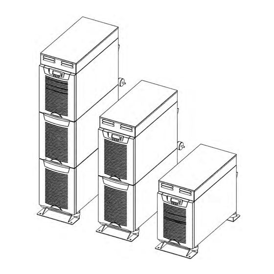
    Figure 2-1: Marine UPS units 8-15 kVA type approved models 2.2 Active-Front technology Traditional input THD filters are no longer needed with this UPS product. The build-in advanced rectifier technology of UPS modules provides perfect sinusoidal input power quality at 0.99 input power factor with harmonic content less than 5% THD(i).
  • Page 12: Advanced Battery Management (Abm)

    The low harmonic currents are due to high input power factor and provide the benefits: • No additional losses in wires and cables • No extra heating of transformers and generators with shortened service life • No false circuit breaker tripping and malfunction •...
  • Page 13: Dnv Type Approval And Abs Product Design Assessment

    2.5 DNV Type approval and ABS product design assessment Eaton 9155 and 9355 Marine UPS units can also be ordered with RFI filters installed at the factory, making them especially suitable for use with vessel's sensitive bridge equipment. With an RFI filter, the electromagnetic compatibility (EMC) requirements are complied with according to system standard (IEC 60945).
  • Page 14: Mechanical Installation

    3 Mechanical installation The UPS and accessories are delivered on a specifically designed pallet that is easy to move with a forklift or a pallet jack. Keep the UPS always in upright position and do not drop the equipment. Do not either stack the pallets because of high-energy batteries involved and the heavy weight.
  • Page 15: Figure 3-1: Type Designation Label

    Figure 3-1: Type designation label 8-10 kVA, 50/60 Hz (1-phase input) & P-164000341 8-15 kVA, 50/60 Hz (3-phase input) User's Guide Revision 1...
  • Page 16: Planning Before Installation

    4 Planning before installation The equipment must be installed in upright position and it requires space both front and back side to enable cooling airflow. The cooling air enters the unit through air inlets in the front and exits from the rear of the unit.
  • Page 17: Table 4-1: The Floor Surface Must Withstand These Weights (Standard Models)

    Equipment Standard Weight (kg) Point (kg/cm²) Distributed (kg/m²) Note 0,09 No batteries UPS + BAT 0,25 Batteries installed UPS + 2 BAT 0,41 1241 Batteries installed UPS + BAT (EMPTY) 0,13 No batteries installed UPS + 2 BAT (EMPTY) 0,16 No batteries installed UPS + TRAFO 0,25...
  • Page 18: Cabinet Installation

    5 Cabinet installation The required distance for UPS units next to each other is 10 mm, but for maintenance and service purposes, it is recommended to leave 100 mm space on both sides of the unit when possible. The same applies to the optional battery cabinets that should be installed next to the UPS cabinet. Figure 5-1: Marine UPS unit with internal input transformer The UPS family has several alternative battery cabinets and configurations depending on the selected back-up time and quality of batteries.
  • Page 19: Transformer Option

    Figure 5-2: UPS with battery module(s) and the rear mounted mechanical bypass switch 5.2 Transformer option The galvanic isolation transformer can be ordered as factory installed. The transformer is an integral part of the UPS unit and it can be connected to the input or the output of the system. Systems with factory installed transformers are referred to as: 9155 NT-model (3 phase in, 1 phase out), 9155 ST- model (1 phase in, 1 phase out) or 9355 NT-model (3 phase in, 3 phase out).
  • Page 20: External Battery Cabinet Option

    Figure 5-3: UPS unit with the factory installed isolation transformer 5.3 External battery cabinet option It’s recommended to install external battery cabinets next to the UPS unit. The battery cabinet can be placed on either side of the UPS unit. Before the installation, check that the battery voltage values, in the type plate of the UPS and the external battery cabinets, are the same.
  • Page 21: Electrical Installation

    6 Electrical installation The customer has to supply the wiring to connect the UPS to the local power source. The electrical installation procedure is described in the following text. The installation inspection and initial start up of the UPS and extra battery cabinet shall be carried out by a qualified engineer with UPS installation experience.
  • Page 22: Power Cables And Protective Fuses

    6.1 Power cables and protective fuses Always use copper cable types to fit terminals with approximately 1.5 Nm torque for different load currents. The Cu cable sizing is based on multi-core cables laid in conduits/trunkings on the wall or on the floor (installation procedure C), ambient temperature 25°C, PVC insulation, surface temperature up to 70°C.
  • Page 23: Ups Models Without An Internal Transformer

    6.2.1 UPS models without an internal transformer Figure 6-1: The location of the power terminals for UPS unit without an internal transformer The installation procedure for models without an internal transformer is described below. Remove the cover(s) of the terminal box of the power cables with a screwdriver. In TA models rectifier input cables are connected to the filter, which is located on top of the unit.
  • Page 24: Ups Models With An Internal Input Transformer

    The IEC/EN 62040-1 safety instructions require the fitting by the user of a warning label on all primary power isolators installed remote from the UPS area. The warning label for electrical maintenance personnel shall carry the following wording or equivalent: “ISOLATE UNINTERRUPTIBLE POWER SUPPLY (UPS) BEFORE WORKING ON THIS CIRCUIT.”...
  • Page 25: Figure 6-3: Cable Connections Into A Transformer Section

    Figure 6-3: Cable connections into a transformer section Connect the conductors of an external battery cabinet cable to the external battery +, - and PE terminals. Check for the correct polarity. See Chapter 6.3 External Battery Cabinet (EBC) installation procedure on page 37. WARNING If available, the internal battery has to be disconnected first because the external battery terminals are hazardous due to the parallel battery string.
  • Page 26: Ups Models With An Internal Output Transformer

    6.2.3 UPS models with an internal output transformer Figure 6-4: The location of the power terminals for UPS unit with an internal output transformer The installation procedure for models with an internal output transformer is described below. Remove the cover(s) of the terminal box of the power cables with a screwdriver. In TA models rectifier input cables are connected to the filter, which is located on top of the unit.
  • Page 27 WARNING If available, the internal battery has to be disconnected first because the external battery terminals are hazardous due to the parallel battery string. Secure the cables with the grommets in the connection box. Fasten the cover of the terminal box and filter enclosure with a screwdriver. The IEC/EN 62040-1 safety instructions require the fitting by the user of a warning label on all primary power isolators installed remote from the UPS area.
  • Page 28: Figure 6-5: Wiring Diagram Of 9155 N-Model (3-Phase In / 1-Phase Out). For Cable And Fuse Sizes, See The Table 6-1

    Figure 6-5: Wiring diagram of 9155 N-model (3-phase in / 1-phase out). For cable and fuse sizes, see the Table 6-1. P-164000341 8-10 kVA, 50/60 Hz (1-phase input) & 8-15 kVA, 50/60 Hz (3-phase input) Revision 1 User's Guide...
  • Page 29: Figure 6-6: Wiring Diagram Of Type Approved 9155 N-Model (3-Phase In / 1-Phase Out). For Cable And Fuse Sizes, See The Table 6-1

    Figure 6-6: Wiring diagram of type approved 9155 N-model (3-phase in / 1-phase out). For cable and fuse sizes, see the Table 6-1. 8-10 kVA, 50/60 Hz (1-phase input) & P-164000341 8-15 kVA, 50/60 Hz (3-phase input) User's Guide Revision 1...
  • Page 30: Table 6-1: Recommended Cable And Fuse Sizes For 9155 N-Model (No Transformer)

    16 mm² 65.2 A 16 mm² 50 A 10 mm² Table 6-1: Recommended cable and fuse sizes for 9155 N-model (No transformer) P-164000341 8-10 kVA, 50/60 Hz (1-phase input) & 8-15 kVA, 50/60 Hz (3-phase input) Revision 1 User's Guide...
  • Page 31: Figure 6-7: Wiring Diagram Of 9155 Nt-Model With Internal Mbs (3-Phase In / 1-Phase Out). For Cable And Fuse Sizes, See The

    Figure 6-7: Wiring diagram of 9155 NT-model with internal MBS (3-phase in / 1-phase out). For cable and fuse sizes, see the Table 6-2. 8-10 kVA, 50/60 Hz (1-phase input) & P-164000341 8-15 kVA, 50/60 Hz (3-phase input) User's Guide Revision 1...
  • Page 32: Figure 6-8: Wiring Diagram Of Type Approved 9155 Nt-Model With Internal Mbs (3-Phase In / 1-Phase Out). For Cable And Fuse

    Figure 6-8: Wiring diagram of type approved 9155 NT-model with internal MBS (3-phase in / 1- phase out). For cable and fuse sizes, see the Table 6-2. P-164000341 8-10 kVA, 50/60 Hz (1-phase input) & 8-15 kVA, 50/60 Hz (3-phase input) Revision 1 User's Guide...
  • Page 33: Table 6-2: Recommended Cable And Fuse Sizes For 9155 Nt-Model

    9155 (3P in/1P Input out) Fusing (FUSE A) Cabling (CABLE 1) rating with different input voltages with different input voltages (kVA) 230 V 400 V 440 V 480 V 690 V 230 V 400 V 440 V 480 V 690 V 8 kVA 50 A 25 A...
  • Page 34: Figure 6-9: Wiring Diagram Of 9155 S-Model (1-Phase In / 1-Phase Out). For Cable And Fuse Sizes, See The Table 6-3

    Figure 6-9: Wiring diagram of 9155 S-model (1-phase in / 1-phase out). For cable and fuse sizes, see the Table 6-3. P-164000341 8-10 kVA, 50/60 Hz (1-phase input) & 8-15 kVA, 50/60 Hz (3-phase input) Revision 1 User's Guide...
  • Page 35: Figure 6-10: Wiring Diagram Of Type Approved 9155 S-Model (1-Phase In / 1-Phase Out). For Cable And Fuse Sizes, See The Table

    Figure 6-10: Wiring diagram of type approved 9155 S-model (1-phase in / 1-phase out). For cable and fuse sizes, see the Table 6-3. 8-10 kVA, 50/60 Hz (1-phase input) & P-164000341 8-15 kVA, 50/60 Hz (3-phase input) User's Guide Revision 1...
  • Page 36: Figure 6-11: Wiring Diagram Of 9155 St-Model With Internal Mbs (1-Phase In / 1-Phase Out). For Cable And Fuse Sizes, See The

    Figure 6-11: Wiring diagram of 9155 ST-model with internal MBS (1-phase in / 1-phase out). For cable and fuse sizes, see the Table 6-3. P-164000341 8-10 kVA, 50/60 Hz (1-phase input) & 8-15 kVA, 50/60 Hz (3-phase input) Revision 1 User's Guide...
  • Page 37: Figure 6-12: Wiring Diagram Of Type Approved 9155 St-Model With Internal Mbs (1-Phase In / 1-Phase Out). For Cable And Fuse

    Figure 6-12: Wiring diagram of type approved 9155 ST-model with internal MBS (1-phase in / 1- phase out). For cable and fuse sizes, see the Table 6-3. 8-10 kVA, 50/60 Hz (1-phase input) & P-164000341 8-15 kVA, 50/60 Hz (3-phase input) User's Guide Revision 1...
  • Page 38: Table 6-3: Recommended Cable And Fuse Sizes For 9155 S Model And 9155 St Model

    9155 (1P INPUT OUTPUT BATTERY in / 1P out) Cabling Nominal Cabling Fusing Cabling Fusing Cabling RATING (CABLE 1) Current (CABLE 2) (FUSE C) (CABLE 3) (FUSE A) (CABLE 1) (KVA) Input Input voltage voltage 230 V 230 V 8 kVA 50 A 10 mm²...
  • Page 39: Figure 6-13: Wiring Diagram Of 9355 N-Model (3-Phase In / 3-Phase Out). For Cable And Fuse Sizes, See The Table 6-4

    Figure 6-13: Wiring diagram of 9355 N-model (3-phase in / 3-phase out). For cable and fuse sizes, see the Table 6-4. 8-10 kVA, 50/60 Hz (1-phase input) & P-164000341 8-15 kVA, 50/60 Hz (3-phase input) User's Guide Revision 1...
  • Page 40: Figure 6-14: Wiring Diagram Of Type Approved 9355 N-Model (3-Phase In / 3-Phase Out). For Cable And Fuse Sizes, See The Table

    Figure 6-14: Wiring diagram of type approved 9355 N-model (3-phase in / 3-phase out). For cable and fuse sizes, see the Table 6-4. P-164000341 8-10 kVA, 50/60 Hz (1-phase input) & 8-15 kVA, 50/60 Hz (3-phase input) Revision 1 User's Guide...
  • Page 41: Figure 6-15: Wiring Diagram Of 9355 Nt-Model (3-Phase In / 3-Phase Out). For Cable And Fuse Sizes, See The Table 6-4

    Figure 6-15: Wiring diagram of 9355 NT-model (3-phase in / 3-phase out). For cable and fuse sizes, see the Table 6-4. 8-10 kVA, 50/60 Hz (1-phase input) & P-164000341 8-15 kVA, 50/60 Hz (3-phase input) User's Guide Revision 1...
  • Page 42: Figure 6-16: Wiring Diagram Of Type Approved 9355 Nt-Model (3-Phase In / 3-Phase Out). For Cable And Fuse Sizes, See The

    Figure 6-16: Wiring diagram of type approved 9355 NT-model (3-phase in / 3-phase out). For cable and fuse sizes, see the Table 6-4. P-164000341 8-10 kVA, 50/60 Hz (1-phase input) & 8-15 kVA, 50/60 Hz (3-phase input) Revision 1 User's Guide...
  • Page 43: Table 6-4: Recommended Cable And Fuse Sizes For 9355 N-Model And 9355 Nt-Model

    9355 (3P in/3P out) INPUT BATTERY UPS RATING (kVA) Fusing Cabling Cabling Fusing Cabling (FUSE A) (CABLE 1) (CABLE 1) (FUSE A) (CABLE 3) 8 kVA 16 A 6 mm² 6 mm² 50 A 10 mm² 10 kVA 20 A 6 mm²...
  • Page 44: External Battery Cabinet (Ebc) Installation Procedure

    6.3 External Battery Cabinet (EBC) installation procedure Figure 6-17: Connections of the UPS unit and External Battery Cabinets The installation procedure is as follows: The EBC is recommended to place next to the UPS unit. NOTE Do not place EBC on the UPS unit. The required minimum distance for UPS unit and EBC is ten millimetres, which is also required distance between two EBCs.
  • Page 45: Figure 6-18: Cable Connections Of The External Battery Cabinet

    the whole system is ready. Remove the IP protection plate first and remove the plate A on the rear side of the EBC to connect cables to EBC’s terminal block X6. Bring cables outside from the EBC by removing the cover plate B. Place the plate A back to the original position and use the cover plate B as a cable clamp.
  • Page 46: Figure 6-19: To Minimise Safety Risk Remove + Or - Cable From Battery String Before Connecting Ups And Ebcs

    Figure 6-19: To minimise safety risk remove + or - cable from battery string before connecting UPS and EBCs P-164000341 8-10 kVA, 50/60 Hz (1-phase input) & 8-15 kVA, 50/60 Hz (3-phase input) Revision 1 User's Guide...
  • Page 47: Software And Connectivity

    7 Software and connectivity The software Suite CD-ROM that is bundled with the UPS contains software distributions and documentation in CD format. Furthermore, the comprehensive connectivity option portfolio includes Web/SNMP adapters for networked environments, Modem card for 24/7 remote monitoring, ModBus/Jbus card for building management system integration, relay interface cards for industrial and facilities use and RS-232 cards for serial communication to one or multiple computers.
  • Page 48: Connection To The Standard Rs-232 Port (X53)

    7.2 Connection to the standard RS-232 port (X53) The standard RS-232 interface uses 9-pin female D-sub connector. It shall be used with the delivered cable for a computer or external modem connection. The data is transmitted with XCP protocol that includes status and meters information about the UPS.
  • Page 49: External Control Connections

    7.3 External control connections The UPS has an input/output interface for direct communication with your computer system. It is located behind the front bezel of the UPS unit. The cables connected to these terminals should be connected to cable clips. Input and output terminals have a functional isolation from terminal to terminal.
  • Page 50: Relay Outputs

    In order to have the UPS running again pins 1 and 2 of connector X52 have to be reconnected and the UPS started manually. The pins must be shorted in order to keep the UPS running. Maximum resistance is 10 ohm. The EPO shall not be galvanically connected to any mains connected circuits. Reinforced insulation to the mains is required.
  • Page 51: Epo Relay (Option)

    • Building alarm 1-6 (These can be activated separately or at the same time with other building alarms.) • Not in use (default) • Shutdown (If active the UPS will shutdown immediately.) • Delayed Shutdown (If active the UPS will shutdown after user configurable delay time. Restart initiated immediately when inactive.) •...
  • Page 52: Earth Fault Monitor (Option)

    7.3.5 Earth fault monitor (option) The earth fault monitor is used to detect earth fault in UPS by monitoring the system's insulation resistance. The device is connected to the supply via terminals A1-A2. Terminal L is connected to the monitored voltage and PE terminal is connected to earth. If the insulation resistance drops below the adjusted alarm value, the red LED goes on and the output relay switches off.
  • Page 53: Web/Snmp Module (Optional)

    Figure 7-6: Location of empty XSlot bays The UPS supports two serial communication devices according to the table below. Independent Multiplexed Configuration XSlot #1 XSlot #2 Std. RS-232 port Default #1 Any Xslot module Any Xslot module Not in use Default #2 Any Xslot module Relay module...
  • Page 54: As400 Relay Module (Optional)

    Figure 7-7: ConnectUPS-X Web/SNMP Module and Environmental Monitoring Probe 7.4.2 AS400 Relay Module (optional) The Relay Module provides potential free relay interface for AS/400 connected computers and industrial applications. The relay interface supports both 15-pin D-sub connector and terminal block connections up to four (4) potential free relays.
  • Page 55: Modus/Jbus Module (Optional)

    7.4.4 Modus/Jbus Module (optional) The Modbus module provides monitoring and integration to the Building Management Software (BMS) such as Wonderware. It features continuous and reliable communication through isolated DB9 ports (RS485/RS232) or a terminal strip (RS485). Figure 7-9: Modus/Jbus Module 8-10 kVA, 50/60 Hz (1-phase input) &...
  • Page 56: User Operations

    8 User operations The UPS has a four-button graphical LCD with backlight. It provides useful information about the unit itself, load status, events, measurements, and settings. The LCD backlight is switched on by pressing any button. It has a timeout that automatically switches off after 15 minutes of inactivity.
  • Page 57: User Settings

    Parallel Single Main Menu Submenu Menu functions Mode Mode CONTROL -> Goto bypass / Battery test/ Display test / Reset error state SETTINGS USER SET- Date / LCD contrast / Change language / TINGS Relay config / Signal inputs / Serial port config / Parallel operation settings / Start screen / User password / Audible alarms / Battery charging method / +list of std.
  • Page 58 Description Available settings Default setting General: Display contrast adjustment + / - Moderate Display language [English], [Spanish], [French], [Ger- English (British) man] Date & Time [xxxx-xx-xx] 0001-01-01 Audible alarms [Normal], [Disabled] Normal Normal screen in display [logo], [mimic] Product name User settings password [Not required], [Set] Not required...
  • Page 59 Description Available settings Default setting XSlot input signal (long break via Nothing XSlot shutdown signal activation Step: 1 sec. 5 sec. delay before the signal is accept- Bypass and synchronisation: Usage of bypass [Enabled], [Disabled] Enabled Require synch at transfer on by- [Required], [Not Required] Not required pass...
  • Page 60: Configuring User Settings

    Description Available settings Default setting Operation priority while rectifier in- [On battery], [On bypass] On battery put break Site wiring fault w/ wrong Neutral [Enabled], [Disabled] Disabled connection Power Strategy [Standard], [High Efficiency] Standard Parallel settings: Parallel unit number [Single unit], [Unit #1], [Unit #2], Single unit [Unit #3], [Unit #4] Parallel operation mode...
  • Page 61: Using Relay Outputs

    Load (kVA) p.f. 0.7 Back-up time Min current Load (kVA) p.f. 0.7 Back-up time Min current 6.5 A 10 h 13 A 10 h 18 A Table 8-3: Required battery charge currents Select Maximum charging current from User Settings menu. Default setting is 3.0 Amps and it is changeable up to 20 Amps.
  • Page 62 Check: ☐ Read the attached safety manual before you work on the unit. ☐ The unit is fixed according to mechanical installation. ☐ The ambient conditions are within specification. ☐ The cooling air will flow freely. ☐ The UPS is grounded properly. ☐...
  • Page 63: Battery Start-Up

    The UPS shall check its internal functions, synchronise to bypass and start to supply the load. The green LED is blinking if there occurs an active notice. In normal operation the green LED is constantly lit if no new active notice such as ‘unsynchronised’ or similar notices present. The output voltage shall be verified from the output measurements screen of the LCD.
  • Page 64: Maintenance

    9 Maintenance All operations inside the unit must be performed only by a service engineer from the manufacturer or from an agent, authorised by the manufacturer. The troubleshooting procedure gives simple remedial if a malfunction occurs in the UPS. The operator should start the trouble shooting if there is an active alarm indicated on the LCD screen.
  • Page 65: Batteries

    Maintenance Interval Cooling fan change ~ 5 years / service Table 9-2: Routine maintenance intervals recommended by the manufacturer 9.1.1 Batteries The condition of the batteries is crucial for operation. The UPS will indicate by audible and visual alarms if the capacity of the battery bank has decreased. The UPS units are provided with the automatic battery test and ABM management function to continuously monitor the condition of the battery bank.
  • Page 66: Maintenance Bypass Switch (Mbs) Operation

    Graphical sign Description Note Yellow 1 UPS is in battery mode. Yellow 2 UPS is in bypass mode. UPS has an active Blinking when new alarm is not alarm. reset and still active. Table 9-3: Description of the LED indicators 9.3 Maintenance bypass switch (MBS) operation The UPS unit comes with a maintenance bypass switch as a standard or optional feature, depending on the ordered configuration.
  • Page 67: Turn Ups From Normal Mode To Mechanical Bypass

    Figure 9-1: The normal (UPS supplying the load) positions of the MBS switches 9.3.1.1 Turn UPS from normal mode to mechanical bypass Figure 9-2: The normal positions of the MBS switches The procedure to turn the UPS to mechanical bypass switch is described below. The normal start position should be as shown below: 8-10 kVA, 50/60 Hz (1-phase input) &...
  • Page 68: Turn Ups From Mechanical Bypass To Normal Mode

    Use the UPS LCD commands to transfer the UPS to static bypass mode. Remember to verify the transfer before proceeding to the next step. Turn the S1 bypass switch to the ON position to bypass the UPS and to disconnect the UPS output: Use the UPS LCD commands to turn the UPS OFF.
  • Page 69: Maintenance Bypass Switch Operation

    Turn the battery breaker F1 and the rectifier input breaker F2 to the ON position. Use the UPS LCD commands to turn the UPS ON and wait until it is fully started. Make sure the UPS is not displaying any alarms. You may verify the output voltage from the meters of the LCD display.
  • Page 70: Turn Ups From Normal Mode To Mechanical Bypass

    Figure 9-4: The normal (UPS supplying the load) positions of the MBS switches 9.3.2.1 Turn UPS from normal mode to mechanical bypass Figure 9-5: The normal positions of the three MBS switches The procedure to turn the UPS to mechanical bypass switch is described below. The normal start position should be as shown below: Use the UPS LCD commands to transfer the UPS to static bypass mode.
  • Page 71: Turn Ups From Mechanical Bypass To Normal Mode

    Turn the S3 switch to the OFF position to disconnect the UPS output: Use the UPS LCD commands to turn the UPS OFF. Turn the battery breaker F1 and the rectifier input breaker F2 to the OFF position. Turn the S2 switch to the OFF position to disconnect the UPS static bypass input: Remount the locking plate of the S1-3 switches to prevent the use of them.
  • Page 72: Figure 9-7: The Normal Positions Of The Mbs Switches In The Normal Mode

    Turn the battery breaker F1 and the rectifier input breaker F2 to the ON position. Use the UPS LCD commands to turn the UPS ON and wait until it is fully started. Make sure the UPS is not displaying any alarms. You may verify the output voltage from the meters of the LCD display.
  • Page 73: Parallel Systems

    10 Parallel systems 10.1 Overview Parallel UPS configurations are recognised as either redundancy or capacity systems. The redundancy system is used to improve the system reliability with N+1 redundant UPS module. The capacity system for its part provides the maximum output power without focusing to the highest system reliability.
  • Page 74: Tie Cabinets

    10.2 Tie cabinets The Tie Cabinets (TCs), provided by UPS manufacturer, has input connections up to three parallel UPS modules. It is also possible to use two redundant UPS modules and one bypass connection. This bypass option can be used for service or test purposes. NOTE It is not allowed to feed the load simultaneously from mains (bypass) and inverter(s) of the UPS unit(s).
  • Page 75: Figure 10-3: Cable Routing Of The Tie Cabinet: 1-Phase Model On The Left And 3-Phase Model On The Right

    Figure 10-3: Cable routing of the Tie Cabinet: 1-phase model on the left and 3-phase model on the right Figure 10-4: 1-phase Tie Cabinet’s wiring diagram with three UPS units 8-10 kVA, 50/60 Hz (1-phase input) & P-164000341 8-15 kVA, 50/60 Hz (3-phase input) User's Guide Revision 1...
  • Page 76: Figure 10-5: 1-Phase Tie Cabinet's Wiring Diagram With Two Ups Units And Bypass Connected

    Figure 10-5: 1-phase Tie Cabinet’s wiring diagram with two UPS units and bypass connected UPS Module Bypass input X1 Rectifier input F2 Cable A Cable C Fuse 1 Cable B Fuse 2 8 kVA 10 mm² 10 mm² 50 A 2,5 mm²...
  • Page 77: Figure 10-6: 3-Phase Tie Cabinet's Wiring Diagram With Three Ups Units

    TC Module Cable D Cable E Cable F 20 kVA 35 mm² 16 mm² (35 mm²)* 24 kVA 70 mm² 35 mm² (70 mm²)* 30 kVA 70 mm² 35 mm² (70 mm²)* 36 kVA 95 mm² 50 mm² 45 kVA 120 mm²...
  • Page 78: Figure 10-7: 3-Phase Tie Cabinet's Wiring Diagram With Two Ups Units And Bypass Connected

    Figure 10-7: 3-phase Tie Cabinet’s wiring diagram with two UPS units and bypass connected UPS Module Cable A Cable C Fuse 1 8 kVA 2,5 mm² 4 mm² 16 A 10 kVA 4 mm² 4 mm² 20 A 12 kVA 6 mm²...
  • Page 79: Table 10-2: Minimum Cable And Fuse Rating For The Different Parallel System With Installation Procedure C * (System Bypass Not Allowed)

    TC Module Cable B Cable D Cable E 24 kVA 10 mm² 16 mm² (10 mm²)* 30 kVA 16 mm² 16 mm² (16 mm²)* 36 kVA 16 mm² 16 mm² 45 kVA 35 mm² 16 mm² Table 10-2: Minimum cable and fuse rating for the different parallel system with installation procedure C * (system bypass not allowed) NOTE Protection fuses need to be used for load cabling if manufacturers Tie Cabinet (or similar) not...
  • Page 80: Xslot Hot Sync Card: Installing And Wiring

    Figure 10-8: Bypass wiring diagram and cable length notes NOTE Signal input cables need to be connected to all UPS when used. 10.3 XSlot Hot Sync card: installing and wiring To enable parallel operation, all the UPSs in the system need the XSlot Hot Sync card (see the Figure and Table below) installed into an open XSlot on the front of the UPS, see Chapter 7.4 XSlot communication (option) on page 45.
  • Page 81: Figure 10-9: Xslot Hot Sync Card And Terminal Interface

    Figure 10-9: XSlot Hot Sync card and terminal interface Terminal J3 Name Description Alarm Programmable UPS alarm. Activated by a re- mote dry contact closure. Alarm Rtn Alarm Relay NC Normally-closed contact opens when UPS is on bypass. Alarm Relay Com Bypass contact return.
  • Page 82: Figure 10-10: Communication Cabling Wiring

    Communication Wiring Termination From UPS 1 CAN card To UPS 2 CAN card To UPS 3 CAN card (if To UPS 4 CAN card (if installed) installed) J3-8 (L) J3-8 (L) J3-8 (L) J3-8 (L) J3-9 (H) J3-9 (H) J3-9 (H) J3-9 (H) Table 10-4: Communication Wiring Termination Figure 10-10: Communication cabling wiring...
  • Page 83: Parallel Operations

    10.4 Parallel operations Start-up: NOTE Before start-up make sure that UPS installations have been carried out correctly and ground connections of both UPS units and parallel module have been connected. Check also that the XSlot Hot Sync cards are installed correctly and the communication line between UPSs is connected according to figure Communication cabling wiring.
  • Page 84 Shutdown: While system is running and UPSs are supporting load, there are two different ways to perform a shutdown. The user can select either to shutdown the whole system or only one UPS. 1. Select TURN SYSTEM OFF from the main menu => All the UPSs in the system will go to stand- by mode.
  • Page 85: Recycling The Used Ups Or Batteries

    11 Recycling the used UPS or batteries Before scrapping UPS or its battery cabinet, the battery bank must be removed. Local requirements must be followed in battery recycling or discard. The removal of batteries is allowed only by authorized service personnel due to high energy and voltage. Do not discard waste electrical or electronic equipment in the trash.
  • Page 86: Dimensional Drawings

    12 Dimensional drawings Figure 12-1: Standard and type approved marine UPS models with one bottom battery module P-164000341 8-10 kVA, 50/60 Hz (1-phase input) & 8-15 kVA, 50/60 Hz (3-phase input) Revision 1 User's Guide...
  • Page 87: Figure 12-2: Standard And Type Approved Marine Ups Models With Two Bottom Battery Modules

    Figure 12-2: Standard and type approved marine UPS models with two bottom battery modules 8-10 kVA, 50/60 Hz (1-phase input) & P-164000341 8-15 kVA, 50/60 Hz (3-phase input) User's Guide Revision 1...
  • Page 88: Figure 12-3: Standard And Type Approved Marine Ups Models With One Bottom Transformer Module

    Figure 12-3: Standard and type approved marine UPS models with one bottom transformer module P-164000341 8-10 kVA, 50/60 Hz (1-phase input) & 8-15 kVA, 50/60 Hz (3-phase input) Revision 1 User's Guide...
  • Page 89: Figure 12-4: Standard And Type Approved Marine Ups Models With Middle Battery And Bottom Transformer Module

    Figure 12-4: Standard and type approved marine UPS models with middle battery and bottom transformer module 8-10 kVA, 50/60 Hz (1-phase input) & P-164000341 8-15 kVA, 50/60 Hz (3-phase input) User's Guide Revision 1...
  • Page 90: Figure 12-5: Standard And Type Approved Marine Ups Models With No Battery Or Transformer Modules

    Figure 12-5: Standard and type approved marine UPS models with no battery or transformer modules P-164000341 8-10 kVA, 50/60 Hz (1-phase input) & 8-15 kVA, 50/60 Hz (3-phase input) Revision 1 User's Guide...
  • Page 91: Figure 12-6: External Battery Cabinet Models With Two And Three Modules

    Figure 12-6: External battery cabinet models with two and three modules 8-10 kVA, 50/60 Hz (1-phase input) & P-164000341 8-15 kVA, 50/60 Hz (3-phase input) User's Guide Revision 1...
  • Page 92: Wiring Diagrams For Internal Transformer

    13 Wiring diagrams for internal transformer Figure 13-1: Internal transformer wirings for 9155 NT model P-164000341 8-10 kVA, 50/60 Hz (1-phase input) & 8-15 kVA, 50/60 Hz (3-phase input) Revision 1 User's Guide...
  • Page 93: Figure 13-2: Internal Transformer Wirings For 9155 St Model

    Figure 13-2: Internal transformer wirings for 9155 ST model 8-10 kVA, 50/60 Hz (1-phase input) & P-164000341 8-15 kVA, 50/60 Hz (3-phase input) User's Guide Revision 1...
  • Page 94: Figure 13-3: Internal Transformer Wirings For 9355 Nt Model

    Figure 13-3: Internal transformer wirings for 9355 NT model P-164000341 8-10 kVA, 50/60 Hz (1-phase input) & 8-15 kVA, 50/60 Hz (3-phase input) Revision 1 User's Guide...
  • Page 95: Technical Data

    14 Technical data Standards 8 kVA 10 kVA 12 kVA 15 kVA Safety IEC 62040-1-1, EN 62040-1-1 and EN 60950 IEC 62040-2, IEC 60945 Product IEC 62040-3 and EN 62040-3 Approvals CE, DNV Type Approval, ABS Product Design Assess- ment (Other classification survey reports on request) Table 14-1: Standards Environment 8 kVA...
  • Page 96: Table 14-3: Mechanical Configuration

    8 kVA 10 kVA 12 kVA 15 kVA 32 battery and transformer: 243 kg 32 battery and transformer: 243 kg TA models: +20kg TA models: +20kg Rear mounted MBS: +15 kg Colour RAL 7035 Table 14-3: Mechanical configuration Characteristics 8 kVA 10 kVA 12 kVA 15 kVA...
  • Page 97: Table 14-5: Ac Input

    8 kVA 10 kVA 12 kVA 15 kVA Voltage (L-N) without 192 to 253 Volts without using battery transformer Voltage (L-N) with input ±5% of system nominal voltage without using battery transformer Frequency 45 to 65 Hz Power factor 0.99 <...
  • Page 98: Table 14-6: Dc Circuit

    8 kVA 10 kVA 12 kVA 15 kVA Battery type VRLA 12 Volts Cut off voltage 1.75 VPC Battery charging Default: 3 Amps, user selectable Maximum charging current: 25 Amps (Step 0.1 A) Table 14-6: DC circuit AC output 8 kVA 10 kVA 12 kVA 15 kVA...
  • Page 99: Warranty

    15 Warranty The product is warranted against defects in design, materials and workmanship for a period of twelve (12) months from its original date of purchase. The local office or distributor may grant a warranty period different to the above and refer to local terms of liability as defined in the supply contract. The UPS manufacturer is not responsible for: •...

This manual is also suitable for:

9155 nt9155 s9155 st9355 n9355 nt

Table of Contents