Table of Contents
Advertisement
Quick Links
Advertisement
Table of Contents

Related Manuals for Burkert 8653 AirLINE Field


Summary of Contents for Burkert 8653 AirLINE Field
- Page 1 Type 8653 AirLINE Field Field module for pneumatic systems Operating Instructions...
- Page 2 We reserve the right to make technical changes without notice. © Bürkert Werke GmbH & Co. KG, 2019 Operating Instructions 1909/01_EUen_00810656 / Original DE...
-
Page 3: Table Of Contents
Type 8653 Type 8653 AirLINE Field Type 8653 ontents Operating instructiOns ........................5 symbols ............................5 1.2 Definition of terms ........................6 intended use ............................7 Basic safety instructiOns ......................8 general infOrmatiOn ........................10 4.1 Contact address .........................10 4.2 Warranty .............................10 4.3 Information on the Internet ......................10 prOduct descriptiOn ........................11 5.1 Intended application range ......................11 5.2 Characteristics ...........................11 5.3 Structure .............................11... - Page 4 Type 8653 cOnfiguratiOn with Bürkert cOmmunicatOr ..............25 10.1 User interface of the Bürkert Communicator ................25 10.2 Establishing a connection between the device and the Bürkert Communicator ....26 10.3 Create the base settings of the field module ................26 10.4 Menu structure ...........................27 10.4.1 Configuration area „Unit 1“ ....................27 10.4.2 Configuration area „General settings“ ................28 cOnfiguratiOn via fieldBus ......................30 11.1 Cabling of büS/CANopen networks ..................30 11.2 Start-up file ..........................31 11.3 Bit-by-bit compilation of the inputs and outputs ..............31 11.3.1 Examples of bit-by-bit allocation of valve units .............31 STArT-Up .............................32 12.1 Starting up via manual override ....................32 12.1.1 Additional element “MO locking”...................33...
-
Page 5: Operating Instructions
Type 8653 Operating instructions OperaTing insTrucTiOns The operating instructions describe the entire life cycle of the device. → Keep these instructions ready to hand at the operation site. Important safety information! Carefully read these instructions. ► Observe in particular the safety instructions, intended use, and the operating conditions. ► Persons who work on the device must read and understand these instructions. ►... -
Page 6: Definition Of Terms
Type 8653 Operating instructions Definition of terms term in these instructions representative for Device, field module AirLINE Field Type 8653 field module Valve Pneumatic slide valve integrated in the field module Actuator, process valve, Pneumatic consumer that is controlled by the field module pneumatic cylinder, pneumatic actuator, pneumatic components büS Bürkert system bus, a communication bus developed by Bürkert based on the CANopen protocol english... -
Page 7: Intended Use
Type 8653 Intended use inTended use The AirLINE Field Type 8653 field module is designed to control and record the switching statuses of pneumatically actuated process valves, pneumatic cylinders and other pneumatically actuated actu- ators directly in the process environment. Use the device for its intended purpose only. Non-intended use of the device may be dangerous to peo- ► ple, nearby equipment and the environment. Do not use the device in the potentially explosive atmosphere. ► The prerequisites for safe and efficient operation are correct transport, storage, assembly, installation, ► start-up, operation, and maintenance. When using the device, observe the permitted data, operating conditions and application conditions. ► This information can be found in the contractual documents, the operating instructions and on the type label. Use the device only in conjunction with third-party devices and components recommended and author- ► ised by Bürkert. Make sure the device is in a technically flawless state before use. ► The device is intended only for use in industrial areas. The device is not suitable for use in applications where there is a risk to life and limb. -
Page 8: Basic Safety Instructions
Type 8653 Basic safety instructions Basic safeTy insTrucTiOns These safety instructions do not consider any contingencies or incidents which occur during assembly, operation and maintenance. The operator is responsible for observing the location-specific safety regula- tions, also with reference to the personnel. risk of injury due to high pressure and uncontrolled movement of the actuators. Before working on the device or system, secure the actuators against moving. ► Before working on the device or system, switch off the pressure. Vent or drain lines. ► risk of injury from electric shock. Before working on the device or system, switch off the power supply. Secure against reactivation. ► Observe applicable accident prevention and safety regulations for electrical equipment. ► risk of burns due to hot device parts. Keep the device away from highly flammable substances and media. ► risk of injury due to improper installation and maintenance. Only trained technicians may perform installation and maintenance work. ► Perform installation and maintenance with suitable tools only. ► risk of injury due to unintentional activation and uncontrolled start-up of the device and system. Secure the device and system to prevent unintentional activation. ►... - Page 9 Type 8653 Basic safety instructions note Electrostatically sensitive components and modules. The device contains electronic components which are susceptible to electrostatic discharge (ESD). Components which come into contact with electrostatically charged people or objects are at risk. In the worst case scenario, these components will be destroyed immediately or will fail after start-up. Meet the requirements specified by EN 61340-5-1 to minimise or avoid the possibility of damage caused ► by sudden electrostatic discharge. Do not touch electronic components when the supply voltage is connected. ►...
-
Page 10: General Information
Contact address germany Bürkert Fluid Control Systems Sales Center Christian-Bürkert-Strasse 13 –17 D-74653 Ingelfingen Phone +49 (0) 7940 - 10 91 111 Fax +49 (0) 7940 - 10 91 448 E-mail: info@burkert.com international The contact addresses can be found on the last pages of the printed Quickstart. And also on the Internet at: www.burkert.com Warranty The warranty is only valid if the device is used as intended in accordance with the specified application conditions. Information on the Internet The operating instructions and data sheets for Bürkert products can be found on the Internet at: www.burkert.com... -
Page 11: Product Description
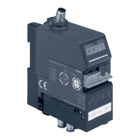
Type 8653 Product description prOducT descripTiOn The AirLINE Field Type 8653 field module is designed for decentralised use in the process environment. The device is simple to install and increases process safety due to the integrated monitoring and diagnostic functions. The body with IP65/67 protection eliminates the need for further protective housing such as a control cabinet. Intended application range The AirLINE Field Type 8653 field module is designed to control and record the switching statuses of pneu- matically actuated process valves, pneumatic cylinders and other pneumatically actuated actuators directly in the process environment. Characteristics Earthed by special bracket •... - Page 12 Type 8653 Product description Circular plug M12, 5-pole operating voltage, input and output signals LCD for messages (information, warnings, errors) LED for status indication Manual overrides Manual Manual override not override switched switched Device markers for marking the valve slots Fig. 2: Structure of AirLINE Field Type 8653 – view from front Earthing bolt M4 Guide bars (for attaching the bracket)
- Page 13 Type 8653 Product description Bracket for assembly on wall or on standard rail In the delivery condition, the device is locked to a bracket for assembly on wall or standard rail. The bracket can be removed from the device for assembly purposes. Bracket (released from the device) Earthing plate (for earthing the device To release the device by means of the from the bracket, push standard rail) back the lever and at the same time slide the device upwards Guide slot...
-
Page 14: Technical Data
Type 8653 Technical data Technical daTa Conformity The device conforms to the EU directives as per the EU Declaration of Conformity (if applicable). Standards The applied standards, which are used to demonstrate conformity with the directives, are listed in the EU type examination certificate and/or the EU Declaration of Conformity (if applicable). Operating conditions note Use safety extra-low voltage in accordance with protection class 3 VDE 0580. ► Type of condition permitted range Ambient temperature –10…+55 °C Storage temperature –10…+60 °C Compressed air quality ISO 8573-1:2010, Class 7.4.4 Nominal operating Continuous operation (100% duty cycle) mode Operating voltage 24 V ± 10% residual ripple at fieldbus interface 1 Vss Protection class 3 in accordance with VDE 0580 Current consumption ≤ 260 mA... -
Page 15: Pilot Pressure Diagram
Type 8653 Technical data Medium pressure* 0...8 bar Pilot pressure* 3...8 bar Electr. power before/ 2 x 0.7 W / 2 x 0.175 W 0.7 W / 0.175 W 0.7 W / 0.175 W after power reduction Current before/after 2 x 29 mA / 2 x ≤ 10 mA 29 mA / ≤ 10 mA power reduction *) O bserve pilot pressure diagram! 6.4.2 Pilot pressure diagram pilot pressure (X-channel) [bar] Fig. 5: Pilot pressure diagram for pneumatic slide valve Type 6534 Circuit function (CF) Circuit function Icon in accordance with ISO 1219-1... -
Page 16: Type Labels (Device Labelling)
Type 8653 Technical data Circuit function Icon in accordance with ISO 1219-1 Description CFM (on request) In idle position, port 2 and port 4 pressurised. 5 1 3 CFN (on request) In idle position, port 2 and port 4 de-energised. 5 1 3 Type labels (device labelling) Type number and Type: 8653 AirLINE Field device designation M12 A - Coded 1. Shield 2. 24 V+ Assignment of circular plug M12, 5-pole 3. GND 4. CAN H Permissible pilot pressure range 5. CAN L (please observe the pilot pressure diagram, “Fig. 5”!) -
Page 17: Assembly
Type 8653 Assembly assemBly Warning risk of injury due to incorrect assembly. Assembly work should be carried out by fully trained personnel only. ► Use suitable tools to perform assembly work. ► The AirLINE Field Type 8653 field module is supplied as a fully assembled device. If defects are dis- covered, the device must be replaced. Fastening types The body with IP65/67 protection eliminates the need for further protective housing such as a control cabinet. The device can be mounted on the following types directly in the process environment: - Assembly on wall using the bracket - Assembly on wall using the lateral fastening holes - Assembly on standard rail using the bracket Assembly on wall Device with bracket... -
Page 18: Assembly On Wall Using The Bracket
Type 8653 Assembly 7.2.1 Assembly on wall using the bracket Caution risk of injury due to sharp edges. The earthing plate on the bracket has sharp edges that can cause cuts. Wear suitable protective gloves. ► preparatory work The bracket is connected to the device in the scope of delivery. For assembly on wall using the bracket, the device must be released from the bracket. → Push back the lever for unlocking the device and at the same time pull the device upwards out of the bracket. -
Page 19: Assembly On Standard Rail
Type 8653 Assembly Assembly on standard rail Caution risk of injury due to sharp edges. The earthing plate on the bracket has sharp edges that can cause cuts. Wear suitable protective gloves. ► Clamping piece Fastening screw Fastening screws for Lever for unlocking the securing to standard rail device from the bracket Fig. - Page 20 Type 8653 Assembly removal from the standard rail → Push back the lever for unlocking the device and at the same time pull the device upwards out of the bracket. → Using a slotted-head screwdriver, carefully turn the fastening screws on the bracket all the way anticlockwise. → Tilt the bracket upward slightly and remove it from the standard rail. english...
-
Page 21: Electrical Connection
Type 8653 Electrical connection elecTrical cOnnecTiOn Caution risk of injury from electric shock. Before working on the device or system, switch off the power supply. Secure against reactivation. ► Observe applicable accident prevention and safety regulations for electrical equipment. ► risk of injury due to incorrect electrical connection work. The electrical connection work should be carried out by fully trained personnel only. ► Use suitable tools to establish the electrical connection. ► Further information on cabling büS networks can be found under the following link: Guide for planning of büS networks note To ensure electromagnetic compatibility (EMC): Only use shielded cables. ► Connect the functional earth (see chapter “8.1” on page 22). ►... -
Page 22: Connecting The Functional Earth
Type 8653 Electrical connection Connecting the functional earth Warning Malfunctioning caused by electrostatic discharge. Electrostatic discharge at the device may cause malfunctioning. Assembly on wall: Depending on the installation situation, use a short cable with a large cross-section ► to connect the device to the functional earth. Assembly on standard rail: Depending on the installation situation, use a short cable with a large ► cross-section to connect the standard rail to the functional earth. Danger due to electromagnetic fields. -
Page 23: Connecting The Functional Earth For Assembly On Standard Rail
Type 8653 Electrical connection 8.1.2 Connecting the functional earth for assembly on standard rail The earthing bolt on the device makes contact with an earthing plate that is integrated into the bracket. When the device is assembled on a standard rail, the earthing plate makes contact with the standard rail. As a result, the device is connected to the earth potential when it is clamped onto the earthed standard rail. Earthing plate Earthing bolt Fig. 11: Earthing by means of the standard rail →... -
Page 24: Pneumatic Connection
Type 8653 Pneumatic connection pneumaTic cOnnecTiOn Danger risk of injury due to high pressure. Before working on the device or system, secure the actuators against moving. ► Before working on the device or system, switch off the pressure. Vent or drain lines. ► risk of injury due to incorrect pneumatic connection work. The pneumatic connection work should be carried out by fully trained personnel only. ► Use suitable tools to establish the pneumatic connection. ► Assignment of the pneumatic connections Exhaust port for auxiliary pilot air (R‘/ 82/84) Pressure port for auxiliary pilot air (X / 12/14) Exhaust port (S/3) Working ports (2: top, 4: bottom) Exhaust port (R/5) Pressure port (P/1) Fig. -
Page 25: Configuration With Bürkert Communicator
The software can be downloaded free of charge from the Bürkert website. In addition to the software, the “USB-büS-interface”, available as an accessory, is required (see chapter “16 Accessories”). The operating instructions for the basic functions of the software can be found on the Bürkert website: www.burkert.com → Type 8920 10.1 User interface of the Bürkert Communicator Menu bar Add interface (connect to büS stick) -
Page 26: Establishing A Connection Between The Device And The Bürkert Communicator
Type 8653 Pneumatic connection 10.2 Establishing a connection between the device and the Bürkert Communicator → Install the Bürkert Communicator software on the PC. → Set the load resistance (at the büS stick or external load resistance). → Use the büS stick to establish a connection between the device and the PC. → Start the Bürkert Communicator. → In the menu bar, click the icon for Add interface. → Select büS stick. Finish. A connection is established between the device and Bürkert Communicator. -
Page 27: Menu Structure
Type 8653 Pneumatic connection 10.4 Menu structure 10.4.1 Configuration area „Unit 1“ Menus Description Detailed view “parameter” Basic settings of the device Valve configuration Adjustment or modification of the base settings. The settings in these menus may also be adjusted as described in section “10.3” Fault handling using the start-up wizard. Diagnostics Type and method of operation of the pilot valves used •... -
Page 28: Configuration Area „General Settings
Type 8653 Pneumatic connection 10.4.2 Configuration area „General settings“ Menus Description/factory settings (if available) Detailed view “parameter” büS Displayed name Device name, can be changed without affecting communication. Location Device installation location, displayed with the device name. Description Free description text, is used for example in tooltips. Advanced Unique device name Factory default number code . Used for partner assignments and should therefore not be changed! Baud rate 50, 125, 250, 500 kbit/s or 1 Mbit/s CANopen address Entry of address/node ID. If the address is already used, the device will switch to a different address (only in büS mode). Bus mode CANopen, büS or standalone device CANopen status This menu is only displayed if “CANopen” is set as the bus mode. - Page 29 Type 8653 Pneumatic connection Menus Description Detailed view “Diagnostics” Shows live values of device Device status Operating duration Device temperature Supply voltage Voltage drops Number of voltage drops since last reboot Min./Max. values Display of maximum and minimum values measured Max. temperature Min. temperature Max. supply voltage Min. supply voltage Device boot counter Current system time büS status...
-
Page 30: Configuration Via Fieldbus
Type 8652 AirLINE valve island. Fieldbus Type ME43 or Type 8652 with büS and fieldbus connection büS Valve island without Field device 1 Field device 2 fieldbus connection Fig. 14: Schematic layout of a bus system with various expansion devices The process for configuring the network is described in the operating instructions of the device in question: Operating instructions for fieldbus gateway ME43: www.burkert.com → Type ME43, chapter “SETTING UP THE büS NETWORK” Operating instructions for AirLINE Type 8652 valve island: www.burkert.com → Type 8652, chapter “Using extension modules (EM)” 11.1 Cabling of büS/CANopen networks Further information on cabling büS/CANopen networks can be found under the following link: Guide for planning of büS networks english... -
Page 31: Start-Up File
Please refer to the documentation of your project design software for instructions regarding the installation of the start-up file. Fieldbus Start-up file CANopen EDS file Download the start-up file and the description of the device-specific objects at: www.burkert.com → Type 8653 → DeviceDescription The standard objects are described in a separate software manual: www.burkert.com → Type 8653 „CANopen Network configuration“ 11.3 Bit-by-bit compilation of the inputs and outputs The field device consists of 1 valve unit with a maximum of 8 valves (= 4 double valves). Each valve unit has 1 byte cyclic output for valve status... -
Page 32: Start-Up
Type 8653 Start-up STArT-UP Warning risk of injury due to incorrect operation. Improper operation may result in injuries as well as damage to the device and its environment. Before start-up, ensure that the operating personnel are familiar with and completely understand the ► contents of the operating instructions. Observe safety instructions and information on intended use. ► Only adequately trained technicians may start up the device. ► 12.1 Starting up via manual override The manual override is ideal for starting up the device and system. The manual override operates without the device being connected to the power supply and enables manual switching of the valves. -
Page 33: Additional Element "Mo Locking
Type 8653 Start-up 12.1.1 Additional element “MO locking” Locking manual override just spring return 180° Locking manual override blocked Fig. 16: Additional element “MO locking” The additional element “MO locking” helps to restrict the manual override. Depending on the position (rotated 0° or 180°) of the clipped-on additional element, the manual override is just spring return or blocked. english... -
Page 34: Marking The Valve Slots
Type 8653 Start-up 12.2 Marking the valve slots The device is supplied with MultiCard format device markers: Device marker ESG 5/10 MC NE WS The individual device markers are fixed to a sprue and can be printed in this form using standardised indus- trial printers (e.g. from Weidmüller). After printing, remove the device markers from the sprue and clip them onto the field module. Fig. 17: Marking the valve slots using MultiCard format device markers english... -
Page 35: Operation
Type 8653 Operation OperaTiOn 13.1 Display elements LCD for messages (information, warnings, errors) LED status display Fig. 18: Display elements for AirLINE Field Type 8653 field module 13.2 Display The device is equipped with an LCD for displaying the status. The switching position and potential error states of the output are displayed graphically on the display. - Page 36 Type 8653 Operation Valve 1 actuated, feedback: “Upper end position reached” Valve 1 actuated, feedback: “Lower end position reached” Short circuit at input 2 of the Example of other possible Alternating message 1 / message 2: upper position feedback unit messages: Short Circuit Message 1 Short circuit at inputs 2–4 of Short Circuit the lower position feedback unit...
-
Page 37: Led Status Display
Type 8653 Operation 13.3 LED status display The LED for displaying the device status changes colour and status similar to NAMUR NE 107. If several device statuses exist simultaneously, the device status with the highest priority is displayed. The priority depends on the severity of the deviation from standard operation (red = failure = highest priority). Status display in accordance with NE 107, edition 2006-06-12 Colour Colour Description Meaning code Failure, error or Standard operation is not possible due to malfunctioning in the malfunction device or peripheral devices. orange Function An internal function/check is performed. This status is exited auto- check matically after a certain time. No user intervention required. yellow Out of Deviation of parameters (e.g. different address/node ID used). -
Page 38: Maintenance, Troubleshooting
Type 8653 Maintenance, troubleshooting mainTenance, TrOuBleshOOTing Warning risk of injury due to incorrect maintenance work. Maintenance may be carried out by authorised technicians only and with the appropriate tools! ► risk of injury due to unintentional switching on of the plant and uncontrolled start-up. Secure system against unintentional activation. ► Ensure controlled start-up after maintenance. ► 14.1 Troubleshooting Fault possible cause remedy Valves do not switch No or insufficient load voltage Check electrical connection Ensure correct load voltage Manual override of the valves not in Move the manual override to the neutral the neutral position... - Page 39 Type 8653 Maintenance, troubleshooting Fault possible cause remedy Valves switching Pressure supply insufficient or not Ensure a sufficient pressure supply delayed or blow off at available (also for upstream devices such as the exhaust ports pressure controllers, maintenance units, shut-off valves, etc.) At valves without auxiliary pilot air: Guarantee minimum operating pressure of 3.0 bar and observe the ratio of pilot pressure to medium pressure in accordance with the pilot pressure diagram (see chapter “6.4.2” on page 15) Insufficient pilot pressure build-up With 5/2-way valves (control function H)
-
Page 40: Fault Messages Lcd
Type 8653 Maintenance, troubleshooting 14.2 Fault messages LCD An overview of the possible display contents can be found in chapter “13.2.1 Display views” on page 35. Message possible cause remedy No message, No or insufficient load voltage Check electrical connection LC display off Ensure correct load voltage Voltage interrupted during firmware Update firmware again update pilot SCC Limit Ch. x Maintenance limit for pilot valve / Replace the pilot valve or maintain the actuator channel X reached actuator and reset the switching cycle counter... -
Page 41: Removal
Type 8653 Removal remOval Danger risk of injury from high pressure and discharge of medium. Before working on the device or system, secure the actuators against moving. ► Before working on the device or system, switch off the pressure. Vent or drain lines. ► Warning risk of injury from electric shock. Before working on the device or system, switch off the power supply. Secure against reactivation. ► Observe applicable accident prevention and safety regulations for electrical equipment. ► risk of injury due to improper removal! Removal should be performed only by trained personnel using suitable tools. ► → Undo the pneumatic connection. → Undo the electrical connection. For assembly using the bracket → Push back the lever for unlocking the device and at the same time pull the device upwards out of the bracket. -
Page 42: Accessories
Type 8653 Accessories accessOries Caution risk of injury and/or damage due to incorrect parts! Incorrect accessories and unsuitable replacement parts may cause injuries and damage the device and its environment. Use original accessories and original spare parts from Bürkert only. ► Accessories Order number USB-büS interfaces set 1 00772426 USB-büS interfaces set 2 (stick with cable only) 00772551 Y-distributor 00772420 Y-distributor with cut-off 00772421 Load resistor, M12 connector 00772424 Load resistor, M12 socket 00772425 Gender changer, M12 connector-connector 00772867 büS cable, M12 angled (wire to socket), 0.7 m 00772626 büS cable (wire to M12 socket), 1 m... -
Page 43: Packaging, Transport
Type 8653 Packaging, transport packaging, TranspOrT note Damage in transit due to inadequately protected devices. Protect the device against moisture and dirt in shock-resistant packaging during transportation. ► Observe permitted storage temperature. ► sTOrage note Incorrect storage may damage the device. Store the device in a dry and dust-free location. ► Storage temperature –10...+60 °C. ►...
Need help?
Do you have a question about the 8653 AirLINE Field and is the answer not in the manual?
Questions and answers