
Subscribe to Our Youtube Channel
Related Manuals for Burkert 8650


Summary of Contents for Burkert 8650
- Page 1 Type 8650 REV.2 Valve block AirLINE Ex Valve block AirLINE Ex with interface to decentral peripheral system SIMATIC ET 200iSP for use in explosive applications Operating Instructions...
- Page 2 „6.3 Information on revision status and compatibility“ on page 17. The operating instructions for device variant REV.1 can be found online at: country.burkert.com We reserve the right to make technical changes without notice. © Bürkert Werke GmbH & Co. KG, 2021...
-
Page 3: Table Of Contents
Type 8650 REV.2 Type 8650 REV.2 ontents OpERaTIng InsTRucTIOns........................6 symbols ............................6 Definition of terms ........................7 InTEnDED usE ............................8 BasIc safETY InsTRucTIOns......................9 nOTEs fOR usE In pOTEnTIallY ExplOsIVE aREas ..............11 safety instructions ........................11 Intended use..........................12 special conditions ........................12 usage conditions ........................13 Backwards compatibility and spare parts ................13... - Page 4 Type 8650 REV.2 10.2 Technical data ..........................31 10.3 Overview .............................32 10.4 Dimensions ..........................33 10.5 pneumatic connections ......................34 10.6 Displays ............................34 10.7 filter ............................35 10.8 pressure gauge module ......................36 DEscRIpTIOn Of ThE ValVE sEgmEnTs ..................37 11.1 structure and function .......................37 11.2 Technical data ..........................38...
- Page 5 Type 8650 REV.2 16.2 Installation instructions ......................63 16.3 Removing pre-installed systems ....................63 16.4 Installation tools and tightening torques ..................64 16.5 position of the fittings and operation elements ................65 16.6 Installing/uninstalling on s7 standard rail (pre-installed system) ..........66 16.7 Installing/uninstalling ET 200isp modules ................67 16.8...
-
Page 6: Operating Instructions
Type 8650 REV.2 Operating Instructions OpERaTing insTRucTiOns The operating instructions describe the entire life cycle of the device. → Keep these instructions ready to hand at the operation site. Important safety information! ▶ Read these instructions carefully. ▶ Observe in particular the safety instructions, intended use and operating conditions. -
Page 7: Definition Of Terms
Device, valve block Valve block AirLINE Ex Type 8650 Valve island Valve block AirLINE Ex Type 8650 in with modules from the decentral peri- phery systems Siemens SIMATIC ET 200iSP I/O system, ET 200iSP Decentral periphery system Siemens SIMATIC ET 200iSP... -
Page 8: Intended Use
Type 8650 REV.2 Intended use inTEndEd usE The device is designed for use in ex areas (see chapter “7 Technical data” for specific classification). It may be used to control pneumatically operated devices. ▶ Device must not be used outdoors unprotected. -
Page 9: Basic Safety Instructions
Type 8650 REV.2 Basic safety instructions Basic safETy insTRucTiOns These safety instructions do not take into account any unforeseen circumstances or events occurring during installation, operation and maintenance. The operator is responsible for observing the location-specific safety regulations, also with reference to personnel. - Page 10 Type 8650 REV.2 Basic safety instructions note Only provide the device with electricity via sImaTIc ET 200isp. ▶ In order to prevent damage to the device, the device must solely obtain its power supply via the I/O system SIMATIC ET 200iSP.
-
Page 11: Notes For Use In Potentially Explosive Areas
Type 8650 REV.2 Notes for use in potentially explosive areas nOTEs fOR usE in pOTEnTially ExplOsiVE aREas Safety instructions Risk of injury due to electrical voltage. ▶ Turn off the power before performing actions within the device (e.g. disconnecting terminal modules) or system. -
Page 12: Intended Use
Type 8650 REV.2 Notes for use in potentially explosive areas Intended use This device is an electrical and pneumatic automation system optimised for use in the control cabinet or switch box. It is used to control pneumatic systems with the specified fieldbus system. It consists of elec- trical and pneumatic components. -
Page 13: Usage Conditions
Type 8650 Revision 2 (REV.2) (i.e. terminal module and valves of the valve segment concerned remain). Valve blocks of Type 8650 REV.1 can be expanded with components of Type 8650 REV.2. See chapter “6.3 Information on revision status and compatibility” for compatibility restrictions. -
Page 14: General Notes
Type 8650 REV.2 General notes gEnERal nOTEs Contact addresses germany Bürkert Fluid Control Systems Sales Centre Christian-Bürkert-Str. 13-17 D-74653 Ingelfingen Tel. +49 (0) 7940 - 10-91 111 Fax +49 (0) 7940 - 10-91 448 E-mail: info@burkert.com International The contact addresses can be found on the back pages of the printed Quickstart. They are also available online at country.burkert.com. -
Page 15: Product Description
The pilot valves integrated in AirLINE Ex allow the actuation of pneumatic actuators in the field, such as process valves or pneumatic cylinders. The Revision 2 (REV.2) of Type 8650 AirLINE Ex is primarily depicted in this document. See chapter “6.3 Information on revision status and compatibility” on page 17 for the differences between REV.1 and REV.2. -
Page 16: Characteristics Of Airline Ex
Type 8650 REV.2 Product description Characteristics of AirLINE Ex • Easy to use. • Automatic formation of supply circuits and data circuits. • Open, flexible and modular structure. • Combination of various valve segments and electric I/O functions for station assembly optimised for space and application. -
Page 17: Information On Revision Status And Compatibility
Overview of revision status REV.1 and REV.2 6.3.2 Information on Revision 2 (REV.2) Type 8650 REV.2 devices are a development of Type 8650 REV.1 and offer the following additional charac- teristics, among others: • Integrated connections for pressure sensors/pressure switches for monitoring supply pressure • Integrated filters for compressed air supply. - Page 18 The electronic modules, pneumatic base modules and connection modules, as well as the single valves of Types 6524, 6525, 6526 and 6527, were revised for Type 8650 REV.2 to implement various optimisations. The interfaces (mechanical, electric, software) of the electronic modules and terminal modules were unchanged.
-
Page 19: Application Range
Product description Application range Valve block AirLINE Ex Type 8650 is designed for decentralised use in industrial environments. Electronics assemblies and armatures can be easily and efficiently combined due to the modular assembly. The device is compliant with degree of protection IP30. - Page 20 Identification of the Ex protection IECEx Ex eb ib IIC T4 Gb Number of the approving body auditing the 0102 production 6.5.2 Type label for unit-specific data Line Type 8650 REV.2 AirLINE Ex ID: 88888888 S/N: 012345 W18MS Fig. 6: Example of a type label for unit-specific data line Description...
-
Page 21: Technical Data
100 % duty cycle (continuous operation) Type 8650 REV.2 meets the required limit values for electrostatic discharge according to EN 61000-4-2. Type 8650 REV.2 doesn‘t reach the increased limit value of 6 kV for contact discharges specified for SIMATIC ET 200iSP. -
Page 22: Pneumatic Data
Type 8650 REV.2 Technical data Pneumatic data Medium dry air oiled or oil-free, neutral gases (hereafter referred to as “compressed air”) Compressed air quality ISO 8573-1: 2010, class 7.4.4 Operating pressure up to 8 bar (bottom and upper limit dependent on valves used) See chapters “10 Description of connection segments”... -
Page 23: Full System Dimensions
Type 8650 REV.2 Technical data Full system dimensions Plug connection D6, D1/4” (optional) Threaded bushing G3/8 + G1/8 plug connection D8; 5/16“ On Siemens S7 standard rail 6ES7390-... nx44 = module quantity x width 44 mm nx66 = module quantity x width 66 mm Fig. 7:... -
Page 24: Assembly Of Full System And Valve Block Airline Ex
Type 8650 REV.2 Assembly of full system and valve block AirLINE Ex assEmBly Of full sysTEm and ValVE BlOck aiRlinE Ex Maximum system expansion Number of up to 32 electronic modules in the complete system Siemens SIMATIC ET 200iSP/ modules Bürkert AirLINE Ex... -
Page 25: Valve Block Airline Ex - Components
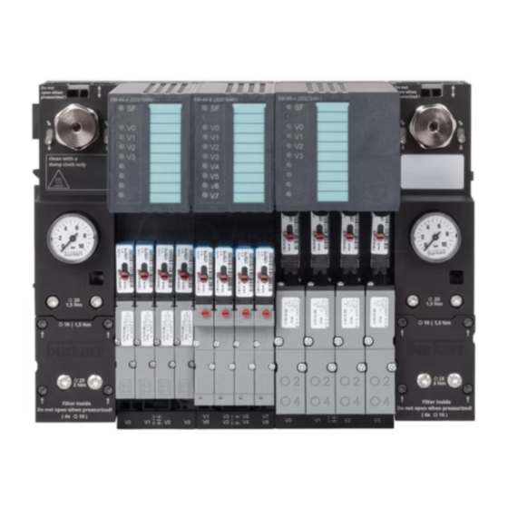
8.3.1 Labelling of modules The AirLINE Ex Type 8650 valve block consists of various modules. These are consolidated in assemblies (“segments”) in favour of simple, use-oriented operation. The assembly of the valve block is schematically presented below and the individual modules are labelled. - Page 26 Type 8650 REV.2 Assembly of full system and valve block AirLINE Ex 8.3.2 Assembly of a complete AirLINE Ex system (example) Fig. 9: Assembly of a complete valve block AirLINE Ex, REV.2 (example) Item Item Connection segment left, equipped with on/ Connection segment centre (interim input) off valve and pressure sensor...
- Page 27 Type 8650 REV.2 Assembly of full system and valve block AirLINE Ex 8.3.4 Electronics assembly – Type ME0... (modular electronics assembly) Electronic module Terminal module Fig. 11: Electronics assembly valve block AirLINE Ex, REV.2, Type ME0... (modular electronics assembly) 8.3.5 Pneumatics – Type MP1... (modular pneumatics) P shutoff (optional) Fig. 12: Pneumatics valve block AirLINE Ex, REV.2, Type MP1... (modular pneumatics) The detailed descriptions of the individual modules can be found in the modules’ chapters.
-
Page 28: Segmenting The Pressure Supply
Type 8650 REV.2 Assembly of full system and valve block AirLINE Ex Segmenting the pressure supply The system’s pressure supply can be segmented by bulkheads in the central P channel between the pneu- matic modules. Various pressure levels and/or media can be used in 1 system for this purpose. -
Page 29: Function Valve Block Airline Ex
Function valve block AirLINE Ex funcTiOn ValVE BlOck aiRlinE Ex Valve block AirLINE Ex Type 8650 has fluidic connections in addition to the electric contacts to the ET 200iSP connection • for central compressed air supply (or other neutral gases), •... -
Page 30: Functional Integration Of The Valve Block In Et 200Isp
Functional integration of the valve block in ET 200iSP Central controller (e.g. PLC) with bus master Ex protection barrier Station 1 Power supply module Valve block airlInE Ex Type 8650 Electrical power supply Station 2 Station ... Station n Fig. 14: Functional integration of the valve block in ET 200iSP (example) Item Item... -
Page 31: Description Of Connection Segments
Type 8650 REV.2 Description of connection segments dEscRipTiOn Of cOnnEcTiOn sEgmEnTs 10.1 Structure and function Connection segments consist of a terminal module and a pneumatic connection module as well as a pressure gauge module (standard for REV.2, optional for REV.1). -
Page 32: Overview
Type 8650 REV.2 Description of connection segments 10.3 Overview Fig. 16: Overview of connection segment valve block AirLINE Ex REV.2 Item Item Pressure gauge for operating pressure display 8 Plug for power bus Screws (2x) for fastening the pressure gauge Protective cover for filter module Clamping bolts (2x) for fastening the valve... -
Page 33: Dimensions
Type 8650 REV.2 24,35 Description of connection segments 10.4 Dimensions 10,5 24,35 10,5 24,35 24,35 54,2 Fig. 17: Dimensions [mm] connection segment valve block AirLINE Ex REV.2 54,2 English... -
Page 34: Pneumatic Connections
Type 8650 REV.2 Description of connection segments 10.5 Pneumatic connections Fig. 18: Pneumatic connections connection segment valve block AirLINE Ex REV.2 Item labelling function port size R/3 / S/5 Exhaust air G3/8 Pre-pilot exhaust air or pre-auxiliary pilot air G1/8 Supply air G3/8 10.6 Displays Pressure gauge can be aligned in any way... -
Page 35: Filter
Type 8650 REV.2 Description of connection segments 10.7 Filter In the pneumatic connection module of each connection segment, a filter is integrated in the input air channel P/1. See chapter “16.10.1 Connection segments” on page 73 for information on maintenance... -
Page 36: Pressure Gauge Module
Type 8650 REV.2 Description of connection segments 10.8 Pressure gauge module Each connection segment of valve block AirLINE Ex REV.2 contains a pressure gauge module. In addition to the pressure gauge installed by default, a pressure switch or pressure sensor can also be ins- talled. -
Page 37: Description Of The Valve Segments
Type 8650 REV.2 Description of the valve segments dEscRipTiOn Of ThE ValVE sEgmEnTs 11.1 Structure and function Valve segments consist of a terminal module, pneumatic base module and electronic module. Valve segments can be assembled with up to 4 valves. 2 variants (44/66mm width) are available for valves with varying widths per valve and air flow rate. -
Page 38: Technical Data
Type 8650 REV.2 Description of the valve segments 11.2 Technical data Valve segment for 11 mm valves Valve segment for 16.5 mm valves Number of valve outlets Dimensions [mm] 44 x 194.3 x 163.5 66 x 190.5 x 163.5 Weight with valves [g] Material Housing Pneumatic modules Electronic module data:... -
Page 39: Overview Valve Segments, Widths Per Valve 44 Mm And 66 Mm
Type 8650 REV.2 Description of the valve segments 11.3 Overview valve segments, widths per valve 44 mm and 66 mm Fig. 23: Overview valve segment (example: width per valve 66 mm) Item Item LED (red) to indicate module status Plug for communication bus LEDs (green) to indicate channel status... -
Page 40: Dimensions
Type 8650 REV.2 Description of the valve segments 11.4 Dimensions 32,4 54,2 Fig. 24: Valve segment dimensions [mm] (example: width per valve 44 mm, this varies for valve segments with width per valve 66 mm, see chapter “7.6 Full system dimensions” on page 23) English... -
Page 41: Pneumatic Connections
Type 8650 REV.2 Description of the valve segments 11.5 Pneumatic connections Danger Risk of injury from high pressure, escaping medium and uncontrolled movement of the actuators. ▶ Secure the actuators against shifting before working on the device or system. ▶ Switch off the pressure before working on the device or system. Vent or empty the lines. - Page 42 Type 8650 REV.2 Description of the valve segments check valves for ventilation channels Check valves in the ventilation channels prevent unintended activation of valves and actuators due to back pressure. The check valves are not suitable for under-pressure applications. p shutoff For pneumatic base modules equipped with a P shutoff (marked on the module, see below), a valve can also be replaced if supply pressure is available.
-
Page 43: Displays
Type 8650 REV.2 Description of the valve segments 11.7 Displays LED “CF” to indicate module status (function like modules ET 200iSP) LEDs “V...” to indicate channel status (see chapter “11.8”) Fig. 27: Display elements of valve segment 11.8 Channel assignment 2 bytes must be projected per valve segment/electronic module. These are occupied and assigned to the... -
Page 44: Diagnostics (Electronic Module)
Type 8650 REV.2 Description of the valve segments 11.9 Diagnostics (electronic module) Consolidated error notification: Yes, locally on electronic module (red LED “CF”) Diagnostics function (readable via bus interface of ET 200iSP): • Channel status diagnostics (channel open, channel short circuited) •... -
Page 45: Description Of The Electronic Module
Type 8650 REV.2 Description of the electronic module dEscRipTiOn Of ThE ElEcTROnic mOdulE 12.1 Structure and function The electronic module is part of the valve segment. It contains the push-in connections for the valves as well as the electronics assembly required to control the valves. -
Page 46: Technical Data
Type 8650 REV.2 Description of the electronic module 12.3 Technical data Electrical data and status indicators: see chapter “11.2 Technical data” on page 38 Identification number of the 171 941 171 942 171 943 module Number of valve outlets 12.4 Overview Fig. 31: Overview of connection segment valve block AirLINE Ex REV.2... -
Page 47: Description Of The Valves
Type 8650 REV.2 Description of the valves dEscRipTiOn Of ThE ValVEs pilot control The valves used in the AirLINE Ex system largely consist of 2 components: • Component 1: the pilot control with degree of protection Ex-i. The pilot control converts the received electrical energy into a pneumatic switch signal. -
Page 48: Pneumatic Valve Types 6524/6525 (Width Per Valve 11 Mm)
Type 8650 REV.2 Description of the valves 13.1 Pneumatic valve Types 6524/6525 (width per valve 11 mm) 13.1.1 Structure and function The pneumatic valves Types 6524 and 6525 consist of an Ex-i pilot solenoid valve (Type 6144) and a pneu- matic seat valve as a strengthener. - Page 49 Type 8650 REV.2 Description of the valves REV.1 REV.2 Single valves Type 6524 and Single valves Type 6524 and Type 6525 with flange profile Type 6525 with flange profile “FM14” “FM20” Fig. 33: Variations in flange profiles of single valves Type 6524 and Type 6525 13.1.2 Technical data Body material PA, PPS...
- Page 50 Type 8650 REV.2 Description of the valves 13.1.3 Order table switching times Description Ident. no. value [l/min] [bar] [ms] [ms] c = nc (normally closed) 2.5– 7 365 620 on request 2(A) 1– 8 on request 1(P) 3(R) on request 11) 12) 1–...
- Page 51 It is actuated by 2x 3/2-way valves of the valve block. unlockable double check valve Type 0498 Fig. 34: Realisation of a 5/3-way function with valve Type 0498 and 2x 3/2-way valves of the valve block You can find further information and data sheets for the unlockable double check valve Type 0498 by entering the type number at country.burkert.com. English...
-
Page 52: Pneumatic Valve Types 6526/6527 (Width Per Valve 16.5 Mm)
Type 8650 REV.2 Description of the valves 13.2 Pneumatic valve Types 6526/6527 (width per valve 16.5 mm) 13.2.1 Structure and function The valves of Types 6526 and 6527 consist of an Ex-i pilot solenoid valve (Type 6106/6144) and a pneu- matic seat valve as a strengthener. - Page 53 Type 8650 REV.2 Description of the valves 13.2.3 Order table switching times value Description Ident. no. [l/min] [bar] [ms] [ms] c = nc (normally closed) 2– 8 263 932 175 674 2(A) -0.9– 8 175 673 1(P) 3(R) 175 723 13, 14) 1–...
-
Page 54: On/Off Valve
Type 8650 REV.2 On/off valve ON/OFF VALVE 14.1 Safety instructions Danger Risk of injury due to uncontrolled movement of the actuators. Actuators connected to the valve block are vented when the on/off valve is disabled. ▶ Before disabling the on/off valve, prevent the actuators from moving or make sure that the actuators do not pose a hazard. -
Page 55: Technical Data
Type 8650 REV.2 On/off valve 14.3 Technical data The on/off valve can be used in a pressure range from 2 to 8 bar. “Auxiliary pilot air” valves can essentially be used in combination with the on/off valve. However, the on/off valve only serves to vent the strengtheners, while the pilot valves must be pressurised, as the auxiliary pilot air is not deactivated by the on/off valve. -
Page 56: On/Off Valve Variants
Type 8650 REV.2 On/off valve 14.4 On/off valve variants product Order no. On/off valve with soleniod degree of protection Ex-i, coil size 5 20002450 On/off valve with soleniod degree of protection Ex-i, coil size 6 on request On/off valve with soleniod degree of protection Ex-m on request 14.5... -
Page 57: Dimensions
Type 8650 REV.2 On/off valve 14.6 Dimensions 58,4 43,6 Fig. 37: Dimensions on/off valve [mm] English... -
Page 58: Pneumatic Connections
Type 8650 REV.2 On/off valve 14.7 Pneumatic connections Fig. 38: Pneumatic connections on/off valve block AirLINE Ex REV.2 Item labelling function port size R/3 / S/5 Exhaust air valve block AirLINE Ex G3/8 Pre-pilot exhaust air or pre-auxiliary pilot G1/8 Supply air G3/8 – Exhaust hole of on/off valve The exhaust hole of the on/off valve must not be sealed. -
Page 59: Pressure Sensor/Pressure Switch
Type 8650 REV.2 Pressure sensor/pressure switch PRESSURE SENSOR/PRESSURE SWITCh 15.1 Safety instructions Danger Risk of explosion. ▶ Only use pressure sensors/pressure switches approved for use in potentially explosive environments. Danger Risk of injury due to high pressure and escaping medium. - Page 60 Type 8650 REV.2 Pressure sensor/pressure switch product Order no. Pressure sensor, WIKA Type IS-3 774 891 • Measurement range 0–10 bar • Electrical connection: Circular plug-in connector M16 x 0.75 • Outlet 4–20 mA (2-conductor, supply voltage 10–30 V) • Types of protection: Among other things, ATEX/IECEx II 1/2G Ex ia IIC T4/T5/T6 Ga/Gb •...
-
Page 61: Overview
Type 8650 REV.2 Pressure sensor/pressure switch 15.4 Overview Fig. 39: Overview of connection segment valve block AirLINE Ex REV.2 with and without pressure sensor Item Item Locking screw Pressure gauge module Insertable adaptor Safety clamp Interface for adaptor Pressure sensor/pressure switch English... -
Page 62: Installation
Type 8650 REV.2 Installation insTallaTiOn 16.1 Safety instructions Danger Risk of injury due to high pressure and escaping medium. ▶ Switch off the pressure before working on the device or system. Vent or empty the lines. Risk of explosion. ▶ To prevent explosion hazards, the power supply for the device must solely be provided via the I/O sys- tem SIMATIC ET 200iSP. -
Page 63: Installation Instructions
▶ Learn more about this in chapter “8.1 Maximum system expansion”). These operating instructions describe the installation and deinstallation of Type 8650 REV.2. These differ in some aspects from Type 8650 REV.1. For installation and deinstallation of Type 8650 REV.1 see the operating instructions of this variant at: country.burkert.com. 16.2... -
Page 64: Installation Tools And Tightening Torques
Type 8650 REV.2 Installation Grabbing points Fig. 40: Grabbing points for removing pre-installed systems 16.4 Installation tools and tightening torques usage Type and size of the tool Tightening torque Operating the locking elements Slot screwdriver size 5 Fitting the clamping bolts on the connection Key for hexalobular-internal screw 1.5 Nm... -
Page 65: Position Of The Fittings And Operation Elements
Type 8650 REV.2 Installation 16.5 Position of the fittings and operation elements Screws (2x) for fastening the Screws (2x) for fastening pressure gauge module the valve Screws (4x) for protective cover for filters Clamping bolts (2x) for fastening the AirLINE Ex on standard rail... -
Page 66: Installing/Uninstalling On S7 Standard Rail (Pre-Installed System)
Type 8650 REV.2 Installation 16.6 Installing/uninstalling on S7 standard rail (pre-installed system) Warning Risk of injuries and property damage. In a non-horizontal installation position, the device is only securely fastened once all clamping bolts are applied as stipulated. ▶ During installation, hold the device in the desired position until all clamping bolts have been applied. -
Page 67: Installing/Uninstalling Et 200Isp Modules
Type 8650 REV.2 Installation 16.7 Installing/uninstalling ET 200iSP modules Installation → Place ET 200iSP modules (terminal modules) on the standard rail and lock onto the AirLINE Ex system. ET 200iSP modules that are attached to the right connection segment lock with the connection segment. - Page 68 Type 8650 REV.2 Installation Unlocking for inacces- sible unlocking slider Fig. 46: Operating unlocking slider English...
-
Page 69: Control Cabinet Installation
Type 8650 REV.2 Installation 16.8 Control cabinet installation The distances that must be adhered to when installing in a control cabinet can be found in the SIMATIC ET 200iSP handbook. The minimum distance specified in “Fig. 47” is recommended for easy replacement of an electronic module. -
Page 70: Assembling, Renovating And Expanding A Device (Valve Block) With Individual Segments
Type 8650 REV.2 Installation 16.9 Assembling, renovating and expanding a device (valve block) with individual segments note ▶ Observe the compatibility requirements (REV.1 <> REV.2); see chapter “6.3 Information on revision sta- tus and compatibility”. Renovating or expanding a device ▶... - Page 71 Type 8650 REV.2 Installation Clamping bolts Inclined tie rods Fig. 48: Adding segments English...
- Page 72 Type 8650 REV.2 Installation 16.9.2 Renovating and expanding the system → Loosen the clamping bolts of the right connection segment (carefully turn the clamping bolts counter- clockwise until they stop). → Loosen the 2 inclined tie rods of the right connection segment.
-
Page 73: Installing/Uninstalling Individual Segments
Type 8650 REV.2 Installation 16.10 Installing/uninstalling individual segments Danger Risk of injury due to high pressure and escaping medium. ▶ Switch off the pressure before working on the device or system. Vent or empty the lines. 16.10.1 Connection segments uninstalling the pressure gauge module →... - Page 74 Type 8650 REV.2 Installation uninstalling the filter → Loosen the 4 screws. → Remove the protective cover for the filter (I). → Pull out the filter (II). Screws Protective cover for filter O-ring Filter Seal for pro- tective cover Crossbars Fig. 50: Installing/uninstalling the filter Installing the filter →...
- Page 75 Type 8650 REV.2 Installation 16.10.2 Valve segments uninstalling the electronic module → Remove valves and any protective caps from the plug contacts. → Move the locking element on the electronic module in the direction of the arrow (I), tilt the module out (II) and remove it (III).
-
Page 76: Installing/Uninstalling The On/Off Valve
Type 8650 REV.2 Installation 16.11 Installing/uninstalling the on/off valve Fig. 52: Installing/uninstalling the on/off valve Item Item Screws (4x) Seal surfaces Spigot Centring holes O-rings Installing the on/off valve on a connection segment Required tool: Key for hexalobular-internal screw size T20 → Ensure that the seal surfaces of the connection segment are not dirty or damaged. - Page 77 Type 8650 REV.2 Installation Electrically connecting the on/off valve → Connect the valve’s solenoid according to the specifications in the valve documentation. • Variants with Ex-i coil: with cable plug (e.g. Type 2518) • Variants with Ex-m coil are equipped with a cast-on cable The on/off valve has no electrical connection to the valve block.
-
Page 78: Installing/Uninstalling Pressure Switch/Pressure Sensor
Type 8650 REV.2 Installation 16.12 Installing/uninstalling pressure switch/pressure sensor Installing the pressure switch/pressure sensor The following method facilitates installation of a pressure sensor, even in limited installation conditions. If the adaptor is easily accessible, it can also remain in the pressure gauge module to install the pressure switch/pressure sensor. - Page 79 Type 8650 REV.2 Installation uninstalling the pressure switch/pressure sensor → Perform the steps listed in “Installing the pressure switch/pressure sensor” in reverse order. The assembly consisting of pressure switch/pressure sensor and adaptor can be arranged in any manner in the pressure gauge module (twisted) so that the connected cable can be laid in the best position.
-
Page 80: Replace Valve
Type 8650 REV.2 Installation 16.13 Replace valve Danger Risk of injury due to pressure change. Only the P channel is blocked during deinstallation of a valve from a base module with P shutoff. The pressure at work outlets A or B is reduced. Any connected actuator is thus also depressurised, which can cause movement. -
Page 81: Connecting Input Air Lines And Exhaust Air Lines
Type 8650 REV.2 Installation 16.14 Connecting input air lines and exhaust air lines Note the following when using one or more on/off valves: Warning Risk of injury due to uncontrolled movement of the actuators. The valve block’s venting function cannot be guaranteed if the on/off valve is used improperly. - Page 82 Type 8650 REV.2 Installation 16.14.2 Connecting exhaust air → Connect the exhaust air to connections R/3 / S/5 of the connection modules. This should be done with the largest possible lines, and a silencer if applicable, with high flow rate values to prevent back pressure.
-
Page 83: Initial Start-Up And Project Planning
Type 8650 REV.2 Initial start-up and project planning INITIAL START-UP AND PROjECT PLANNING 17.1 Safety instructions Danger Risk of injury due to high pressure and escaping medium. ▶ Switch off the pressure before working on the device or system. Vent or empty the lines. -
Page 84: Communication Connection/Projecting
Type 8650 REV.2 Initial start-up and project planning 17.2 Communication connection/projecting The valve segments communicate with the interface module via the rear wall bus system of the ET 200iSP. This exchanges the input data, output data, parameter data, configuration data and diagnostics data via the overriding bus system with a central master (PLC). -
Page 85: Configuring Hardware With The Dmd, With Simatic Tia Portal As An Example
Type 8650 REV.2 Initial start-up and project planning 17.3 Configuring hardware with the DMD, with SIMATIC TIA Portal as an example A software such as SIMATIC TIA Portal from Siemens is required to configure the bus master. Use the following program versions to ensure the hardware’s compatibility: •... - Page 86 Type 8650 REV.2 Initial start-up and project planning Connection segments are passive and are not projected (see also chapter “10.1” on page 31). → Select the desired modules from the ET 200iSP catalogue branch and drag them to the respective slot of the ET 200iSP station via drag-and-drop.
-
Page 87: Accessing The Acyclical Parameters, With Simatic Pdm As An Example
Type 8650 REV.2 Initial start-up and project planning 17.4 Accessing the acyclical parameters, with SIMATIC PDM as an example A program such as Siemens Process Device Manager (PDM) is required to access the acyclical parameters of the modules. The respective EDD (file package) must be imported into the program device catalogue before the AirLINE Ex module can be accessed. - Page 88 Type 8650 REV.2 Initial start-up and project planning → Add the new object. Fig. 58: Adding the new object → Select the device type to ad a new device. Fig. 59: Selecting the device type English...
- Page 89 Type 8650 REV.2 Initial start-up and project planning → Define the station name and bus address. Fig. 60: Defining the station name and bus address → Add the function modules. Fig. 61: Adding the function modules English...
- Page 90 Type 8650 REV.2 Initial start-up and project planning → Set the desired number of equivalent modules. Fig. 62: Setting the number of equivalent modules → Select the module type via the menu “Assign”. Fig. 63: Selecting the module type English...
- Page 91 Type 8650 REV.2 Initial start-up and project planning → Confirm the module selection with “OK”. Fig. 64: Confirming the module selection English...
- Page 92 Type 8650 REV.2 Initial start-up and project planning 17.4.1 Example with 2 different function modules → Select the head station. Fig. 65: Selecting the head station → Open station to access acyclical functions. Fig. 66: Opening the station English...
- Page 93 Type 8650 REV.2 Initial start-up and project planning → Select access type (specialist: full access; maintenance: limited access). Fig. 67: Selecting the access type → Select head station to obtain parameters of interface module and overview of station assembly. Fig. 68: Parameters of interface module and overview of station assembly English...
- Page 94 Type 8650 REV.2 Initial start-up and project planning Fig. 69: Parameters of an AirLINE Ex pneumatic module English...
-
Page 95: Acyclical Parameters Of Airline Ex Modules
Type 8650 REV.2 Initial start-up and project planning 17.5 Acyclical parameters of AirLINE Ex modules 17.5.1 Parameters that are modularly displayed or can be modularly changed name Value unit status 4 DO Bürkert 11 mm PDM_ConfigurationTool 1: PDM Initial value... - Page 96 Type 8650 REV.2 Initial start-up and project planning 17.5.2 Access rights maintenance/specialist Some of the parameters described below can only be changed if PDM access is set to SPECIALIST. You can learn more about reading and writing rights in the online help for the SIMATIC PDM program.
- Page 97 Type 8650 REV.2 Initial start-up and project planning 17.5.4 Parameters displayed by channel or which can be altered by channel name Value unit status channel 0 Channel enable enabled Behaviour for CPU/Master-STOP Switching replacement value Initial value Forced value # # # pilot valve...
- Page 98 Type 8650 REV.2 Initial start-up and project planning 17.5.7 Functions of the actuator parameter (that is connected to this channel’s pilot valve) • switching cycle counter diagnostics approval (read/write) Defines whether a diagnostics alert will be generated when the warning parameter of the switching cycle counter is exceeded.
-
Page 99: Using Hsp With Simatic Step 7/Tia Portal
→ In the menu “Extras” in SIMATIC STEP 7 select the command “Support packages”. → In the subsequent dialogue select “Add from the file system”, and mark and install “HSPXXXX...”. Fig. 70: Install HSP After installation is complete, the valve modules AirLINE Ex 8650 are integrated in the hardware catalogue. English... - Page 100 Type 8650 REV.2 Initial start-up and project planning 17.6.3 Using the hSP → Select ET 200iSP from the branch “Decentral periphery”. Fig. 71: Selecting the interface module English...
- Page 101 Type 8650 REV.2 Initial start-up and project planning → Select AirLINE Ex modules from the branch “Pneumatic modules” and assign the plugs of the ET 200iSP station. Fig. 72: Assignment of modules English...
- Page 102 Type 8650 REV.2 Initial start-up and project planning changing the parameters in hsp → Mark the module. This displays its parameters, some of which can also be changed. Fig. 73: Changing the parameters of a module Changes to the settings of the switching cycle counters can currently only be made via SIMATIC PDM.
-
Page 103: Use Of A Hup Under Simatic Pcs7
Type 8650 REV.2 Initial start-up and project planning 17.7 Use of a hUP under SIMATIC PCS7 When using a HUP for the configuration, the required modules are created automatically for the valve block modules. These modules contain all the necessary data and diagnostics. - Page 104 Type 8650 REV.2 Initial start-up and project planning Fig. 75: Projecting PCS7 (HW-Konfig) The filter in the hardware catalogue must be set to “Standard” so that the AirLINE Ex modules are displayed. Changes to the switching cycle counter settings can currently only be made via SIMATIC PDM (can be integrated in PCS7).
-
Page 105: Serialisation Data Set
Serialisation data set sERialisaTiOn daTa sET The serialisation data of fully assembled Type 8650 systems are available as an electronic data set for docu- mentation purposes. The data set contains the identification numbers and serial numbers of all Ex-related components (valves, electronic modules and terminal modules). - Page 106 Type 8650 REV.2 Serialisation data set Identification number of valve block Serial number of valve block Identification number of 1st electronic module Serial number of 1st electronic module Identification number of 2nd electronic module Serial number of 2nd electronic module...
-
Page 107: Servicing And Maintenance
Only certain activities are allowed during operation in a potentially explosive area. In addition to the activities listed in the documentation for SIMATIC ET 200iSP, the following also apply to AirLINE Ex Type 8650: Pulling/plugging valves and electronic modules during operation in Zone 1 and Zone 2, see chapter“19.3 Upkeep”. - Page 108 Type 8650 REV.2 Servicing and maintenance note Only provide the device with electricity via sImaTIc ET 200isp ▶ In order to prevent damage to the device, the device must solely obtain its power supply via the Power- Supply module of the ET 200iSP.
-
Page 109: Maintenance
Type 8650 REV.2 Servicing and maintenance 19.2 Maintenance 19.2.1 Maintaining modules The AirLINE Ex system modules do not require maintenance if used in accordance with these operating instructions. If coarse residue occurs in the compressed air supply lines, it may accumulate in the filter of the connection segments (only REV.2). -
Page 110: Upkeep
Type 8650 REV.2 Servicing and maintenance 19.3 Upkeep Danger Risk of injury due to high pressure and escaping medium. ▶ Switch off the pressure before working on the device or system. Vent or empty the lines. The valves can show signs of wear over time (e.g. tightness may deteriorate). Valves opened when necessary must be replaced as described below. - Page 111 Type 8650 REV.2 Servicing and maintenance 20 Ncm 30 Ncm 20 Ncm 30 Ncm 19.3.2 Replacing the electronic module in operation SIMATIC ET 200iSP only allows the removal of on individual electronic module in operation. If mul- tiple electronic modules are being removed simultaneously, the station reports the disruption.
-
Page 112: Troubleshooting
Type 8650 REV.2 Servicing and maintenance 19.4 Troubleshooting fault possible cause Valves do not switch. No operating voltage or operating → Check the electrical connection. voltage too low. → Ensure the correct operating voltage. → Bring manual override to zero position. -
Page 113: Repairs
Type 8650 REV.2 Servicing and maintenance fault possible cause CF LED is lit. Wrong configuration. → Use the corresponding module from the hardware catalogue. → Check whether the valve is properly Valve diagnostics responds (short circuit, open output). installed. → Replace defective valves. -
Page 114: Decommissioning
Type 8650 REV.2 Decommissioning dEcOmmissiOning 20.1 Safety instructions Danger Risk of injury due to high pressure and escaping medium. ▶ Switch off the pressure before working on the device or system. Vent or empty the lines. Risk of injury from electric shock. -
Page 115: Accessories
Type 8650 REV.2 Accessories accEssORiEs 21.1 System accessories Description Ident. no. Blind plate for sealing an unused valve plate 661 092 Width per valve 11 mm (valves Type 6524 and 6525) Blind plate for sealing an unused valve plate 653 765 Width per valve 16.5 mm... -
Page 116: Storage
Type 8650 REV.2 Storage sTORagE note Incorrect storage may damage the device. ▶ Store the device in a dry and dust-free location. Storage temperature -40 – +70 °C The following information applies to assemblies stored in the original packaging. Requirement... -
Page 117: Packaging And Transport
Type 8650 REV.2 Packaging and transport packaging and TRanspORT note Transport damages. Inadequately protected devices may be damaged during transport. ▶ Protect the device against moisture and dirt in shock-resistant packaging during transportation. ▶ Avoid exceeding or dropping below the permitted storage temperature.
Need help?
Do you have a question about the 8650 and is the answer not in the manual?
Questions and answers