
Related Manuals for Siemens Milltronics MWL Weight Lifter


Summary of Contents for Siemens Milltronics MWL Weight Lifter
- Page 1 Belt Scales Milltronics MWL Weight Lifter Operating Instructions 11/2011 Milltronics...
- Page 2 The user is responsible for all changes and repairs made to the device by the user or the user’s agent. All new components are to be provided by Siemens Milltronics Process Instruments. Restrict repair to faulty components only.
- Page 3 ___________________ Milltronics MWL Weight Lifter Introduction ___________________ Safety notes ___________________ Description Milltronics ___________________ Installing/Mounting Belt Weighing Accessories ___________________ Milltronics MWL Weight Lifter Connecting ___________________ Commissioning Operating Instructions ___________________ Operation ___________________ Service and maintenance ___________________ Technical data ___________________ Dimension drawings ___________________...
- Page 4 Note the following: WARNING Siemens products may only be used for the applications described in the catalog and in the relevant technical documentation. If products and components from other manufacturers are used, these must be recommended or approved by Siemens. Proper transport, storage, installation, assembly, commissioning, operation and maintenance are required to ensure that the products operate safely and without any problems.
-
Page 5: Table Of Contents
Table of contents Introduction..............................5 The manual ............................5 Safety notes............................... 7 General safety instructions ......................7 Description..............................9 Milltronics MWL Weight Lifter ......................9 Applications............................9 MWL components ........................10 Calibration weight arrangement ....................11 Installing/Mounting........................... 13 Introduction ..........................13 Installation procedure........................14 4.2.1 Drill crank body mounting holes....................14 4.2.2... - Page 6 MWL installation drawing for the MSI or MMI belt scale............. 52 10.2.5.1 Retrofitting an MSI or MMI belt scale..................53 10.2.6 MWL (electronic version) dimensions ..................56 Appendix A: Customer calculations ......................57 Milltronics MWL Weight Lifter Operating Instructions, 11/2011, 7ML19985CR03-03...
-
Page 7: Introduction
Note Safety The Milltronics MWL Weight Lifter is to be used only in the manner outlined in this manual, otherwise protection provided by equipment may be impaired. It is your responsibility to read this manual before installing and starting up any component of the weighing system to which the weight lifter is being applied. - Page 8 Introduction 1.1 The manual Milltronics MWL Weight Lifter Operating Instructions, 11/2011, 7ML19985CR03-03...
-
Page 9: Safety Notes
Note Alterations to the product, including opening or improper repairs of the product, are not permitted. If this requirement is not observed, the CE mark and the manufacturer's warranty will expire. Milltronics MWL Weight Lifter Operating Instructions, 11/2011, 7ML19985CR03-03... - Page 10 Safety notes 2.1 General safety instructions Milltronics MWL Weight Lifter Operating Instructions, 11/2011, 7ML19985CR03-03...
-
Page 11: Description
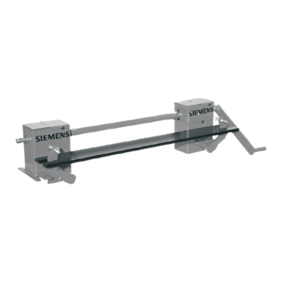
Description Milltronics MWL Weight Lifter Milltronics MWL Weight Lifter is a mechanical calibration weight lifter for MUS, MBS, MCS, MSI and MMI belt scales. The MWL mechanically raises and lowers the static calibration (test) weights used to calibrate Milltronics belt scales. It stores the weights securely between the belt strands, above the calibration weight support arms, and allows the operator to lower and apply the weights safely without having to lean into the conveyor. -
Page 12: Mwl Components
3.3 MWL components MWL components The Milltronics MWL Weight Lifter consists of the following components: ● left-handed and right-handed crank body, each connected to a lifting arm with guide-pin ● torque tube, to connect the left and right crank shafts ●... -
Page 13: Calibration Weight Arrangement
Description 3.4 Calibration weight arrangement Calibration weight arrangement Flat bar calibration weights ① flat bar base-bar weight ② flat bar calibration weights ③ U-bracket (supplied with MWL) Round bar calibration weight Milltronics MWL Weight Lifter Operating Instructions, 11/2011, 7ML19985CR03-03... - Page 14 Description 3.4 Calibration weight arrangement Milltronics MWL Weight Lifter Operating Instructions, 11/2011, 7ML19985CR03-03...
-
Page 15: Installing/Mounting
AC gearmotor already installed in place of the handle. The control panel for the electronic version has four mounting holes on the back which must be sealed and rigidly mounted. Milltronics MWL Weight Lifter Operating Instructions, 11/2011, 7ML19985CR03-03... -
Page 16: Installation Procedure
1. Measure and mark the locations of the mounting holes for each of the crank bodies. The left- handed unit turns clockwise to raise weights and the right-handed unit turns counter- clockwise. 2. Drill the holes as specified for 12 mm (1/2") mounting hardware. Milltronics MWL Weight Lifter Operating Instructions, 11/2011, 7ML19985CR03-03... -
Page 17: Mount Crank Bodies
② crank body ③ input shaft ④ shim (if required) ⑤ bolt ⑥ washer ⑦ Note The crank bodies must be left loose to allow for the torque shaft installation. Milltronics MWL Weight Lifter Operating Instructions, 11/2011, 7ML19985CR03-03... -
Page 18: Mount Torque Shaft
5. Hand tighten the bolts, nuts, and washers that hold the torque tube onto the connecting shafts. ① torque tube ② connecting shaft (2) ③ lifting arm in raised position (2) ④ locking pin installed, locking MWL in storage position Milltronics MWL Weight Lifter Operating Instructions, 11/2011, 7ML19985CR03-03... -
Page 19: Install Crank Handle (Manual Version)
2. Remove the plastic cap from the input shaft on the selected side. 3. If the shaft extension is required, slide the female end of the extension over the exposed input shaft, and secure the extension with a bolt, nut, and washer. Milltronics MWL Weight Lifter Operating Instructions, 11/2011, 7ML19985CR03-03... - Page 20 (tethered to crank body) ② input shaft ③ optional shaft extension ④ locking ball-pin (tethered to crank handle) ⑤ crank handle (female end) ⑥ bolt ⑦ hole for storage on locking ball-pin Milltronics MWL Weight Lifter Operating Instructions, 11/2011, 7ML19985CR03-03...
-
Page 21: Test The Unloaded Mwl
3. Retighten the bolts that mount the two crank bodies. 4. Check again, and repeat the process until the MWL operates smoothly, with no resistance. Milltronics MWL Weight Lifter Operating Instructions, 11/2011, 7ML19985CR03-03... -
Page 22: Install Calibration Weights
1. Turn the crank handle, or use the control buttons, until the lifting arms are fully lowered. 2. Place the base-bar weight into position on the calibration weight supports of the Milltronics belt scale. Milltronics MWL Weight Lifter Operating Instructions, 11/2011, 7ML19985CR03-03... - Page 23 4. Gently turn the crank handle, or use the control buttons, until the lifting arms are fully raised: you may need to guide the notches in the base-bar weight in line with the lifting arms initially. ① lifting arm engages the notch on the end of the base-bar weight Milltronics MWL Weight Lifter Operating Instructions, 11/2011, 7ML19985CR03-03...
- Page 24 - on MSI scales: 12.5 mm (0.5") ② vertical arm of calibration weight support ③ base-bar weight 7. Recheck the crank body alignment: if necessary, see Align the crank bodies to each other (Page 19). Milltronics MWL Weight Lifter Operating Instructions, 11/2011, 7ML19985CR03-03...
-
Page 25: Test The Loaded Mwl
- on MSI scales: 12.5 (0.5") ② vertical arm of calibration weight support ③ calibration weights 3. Recheck the crank body alignment: if necessary, see Align the crank bodies to each other (Page 19). Milltronics MWL Weight Lifter Operating Instructions, 11/2011, 7ML19985CR03-03... -
Page 26: Shim The Mwl
3. Remove the bolt, nut, and washer on one crank body and position the shim between the crank body and the conveyor stringer: it should not be necessary to loosen or remove the torque tube connecting the two crank bodies. Milltronics MWL Weight Lifter Operating Instructions, 11/2011, 7ML19985CR03-03... - Page 27 5. Repeat the same procedure with the other crank body, then recheck the crank body alignment. See Recheck crank body alignment (Page 24). ① bolt ② shim, if required ③ washer ④ Milltronics MWL Weight Lifter Operating Instructions, 11/2011, 7ML19985CR03-03...
- Page 28 3. Repeat the shimming procedure until the lifting arms raise the calibration weights at least 10 mm (0.38") above the calibration weight supports. 4. Tighten the torque shaft bolts and the crank-body mounting bolts, then recheck all clearances. The MWL installation is now complete. Milltronics MWL Weight Lifter Operating Instructions, 11/2011, 7ML19985CR03-03...
-
Page 29: Connecting
② ⑦ enclosure ground stud M8 (15MM) copper enclosure wall ③ ⑧ M8 nut star or serrated washer ④ ⑨ lockwasher lockwasher ⑤ ⑩ secondary bond back plate ground wire M8 nut Milltronics MWL Weight Lifter Operating Instructions, 11/2011, 7ML19985CR03-03... - Page 30 Connecting 5.1 Connecting the MWL (electronic version) The electronic version of the Milltronics MWL Weight Lifter comes with an AC gearmotor, two magnetic proximity sensors, and an optional electronic control panel. The motor is available in two different three-phase power configurations: 220-240/380-420/440-480 and 500-600 V AC. It can be controlled locally using the pushbuttons on the panel, or remotely by the customer's PLC or DCS.
-
Page 31: Connection Diagram
[See Connect the remote PLC (Page 34) ] ⑤ magnetic proximity sensor connection terminals [See Connect the sensor junction box (Page 33) ] ⑥ motor and brake connection terminals [See Connect the motor and brake (Page 32) ] Milltronics MWL Weight Lifter Operating Instructions, 11/2011, 7ML19985CR03-03... -
Page 32: Connection Procedure
Connect input power Connect the input power supply to the 3-phase power connection terminal on the control panel as shown below. Refer to the connection diagram (Page 29) for more details. ① incoming power Milltronics MWL Weight Lifter Operating Instructions, 11/2011, 7ML19985CR03-03... -
Page 33: Connect The Control Transformer
Class CC ATDR1 (600 V, 1.0 A) fuse across terminals X1 - XF of the Secondary of the MT150L control transformer. Class CC ATDR4 (600 V, 4.0 A) fuse for 220-240/380-420/440-480 V 3-phase supply Class CC ATDR2-1/2 (600 V, 2.5 A) fuse for 500-600 V 3-phase supply. Milltronics MWL Weight Lifter Operating Instructions, 11/2011, 7ML19985CR03-03... -
Page 34: Connect The Motor And Brake
2. Connect the brake release to the control panel using an appropriate 2-conductor cable, as shown in the diagram below. 3RU1611-0DB0 14/22 4 T2 6 T3 2 T1 NO/NC ① motor ② brake coil Refer to the connection diagram (Page 29) for more details. Milltronics MWL Weight Lifter Operating Instructions, 11/2011, 7ML19985CR03-03... -
Page 35: Connect The Sensor Junction Box
Depending on your configuration and the orientation of the sensor junction box, the sensor signals may be reversed. The input of these switches is set at the factory; check the termination of the wires to ensure the up and down switches are properly connected. Milltronics MWL Weight Lifter Operating Instructions, 11/2011, 7ML19985CR03-03... -
Page 36: Connect The Remote Plc (Optional)
The connections between terminals labeled A2 have already been made internally. CAUTION If the control panel is connected for use remotely, a series circuit for emergency stop operation should be included in the system. Milltronics MWL Weight Lifter Operating Instructions, 11/2011, 7ML19985CR03-03... -
Page 37: Commissioning
2. Press the UP pushbutton and observe the direction of travel. 3. If the MWL is moving UP, the motor is connected correctly and you may now proceed to operate the MWL in a normal fashion. Milltronics MWL Weight Lifter Operating Instructions, 11/2011, 7ML19985CR03-03... - Page 38 – Reverse two of the motor phase wires to reverse the direction of the motor. 5. Apply main power and repeat steps 1 and 2 to ensure that the direction of motor control is now correct. Milltronics MWL Weight Lifter Operating Instructions, 11/2011, 7ML19985CR03-03...
-
Page 39: Operation
(Please see the manuals for the Milltronics Belt Scale and Integrator, for the appropriate calibration procedures.) ① flat bar calibration weights applied ② lifting arms lowered ③ calibration weight supports (2) Milltronics MWL Weight Lifter Operating Instructions, 11/2011, 7ML19985CR03-03... - Page 40 Two clips on the side of the crank body help to hold the handle in position. 4. Cover the input shafts with a guard if they present a hazard to personnel when the MWL is not in use. Milltronics MWL Weight Lifter Operating Instructions, 11/2011, 7ML19985CR03-03...
-
Page 41: Operation (Electronic Version)
While the MWL is moving, the red DOWN indicator will blink. Once it stops, the indicator will remain on. 3. Refer to the manuals for the Milltronics Belt Scale and Integrator, to perform the appropriate calibration procedures. Milltronics MWL Weight Lifter Operating Instructions, 11/2011, 7ML19985CR03-03... -
Page 42: Remote Mode
This energizes the remote relay coil and closes the 3 contacts required for the PLC ENABLE signal and the UP and DOWN operation signals. Note In remote mode, the front panel pushbuttons, with the exception of the EMERGENCY STOP button, are disabled. Milltronics MWL Weight Lifter Operating Instructions, 11/2011, 7ML19985CR03-03... -
Page 43: Service And Maintenance
Before starting a calibration procedure, be sure to check that there is no material accumulation in the three areas described below. ① top surface of calibration weights ② top surface of calibration weight support ③ inside crank body housing Milltronics MWL Weight Lifter Operating Instructions, 11/2011, 7ML19985CR03-03... - Page 44 Note The threaded shaft and guide plates are normally not accessible to the human hand: do not force any foreign matter into the area during operation. Milltronics MWL Weight Lifter Operating Instructions, 11/2011, 7ML19985CR03-03...
-
Page 45: Technical Support
● Information about field service, repairs, spare parts and lots more under "Services." Additional support Please contact your local Siemens representative and offices if you have additional questions about the device Find your contact partner at: Local contact person (http://www.siemens.com/automation/partner) - Page 46 Service and maintenance 8.2 Technical support Milltronics MWL Weight Lifter Operating Instructions, 11/2011, 7ML19985CR03-03...
-
Page 47: Technical Data
Some belt scales require specific order configurations for use with the MWL. Idler spacing minimum of 610 mm (24") Calibration weight capacity 750 lbs. (340 kg) Crank arm (manual version) mechanical advantage 20:1 number of revolutions required for raising or lowering Milltronics MWL Weight Lifter Operating Instructions, 11/2011, 7ML19985CR03-03... - Page 48 15.75 x 19.68 x 8.27" (400 x 500 x 210mm) Approvals (manual version) General CE, C-TICK Approvals (electronic version) General CE, C-TICK US/C The Milltronics MWL Weight Lifter is in compliance with Directive 98/37/EC. Milltronics MWL Weight Lifter Operating Instructions, 11/2011, 7ML19985CR03-03...
-
Page 49: Dimension Drawings
Dimension drawings 10.1 Calibration weight dimensions ① conveyor A dimension + 65 mm (2.56") Milltronics MWL Weight Lifter Operating Instructions, 11/2011, 7ML19985CR03-03... -
Page 50: Installation Drawings
② ⑥ 133 mm (5.22") belt ③ ⑦ 214 mm (8.43") 10 mm (0.38") minimum clearance from vertical arm to weights ④ ⑧ 522 mm (20.55") base-bar weight centered on lifting arm Milltronics MWL Weight Lifter Operating Instructions, 11/2011, 7ML19985CR03-03... -
Page 51: Mwl Installation Drawings For The Mus-Hd Heavy Duty Belt Scale
② ⑥ 133 mm (5.22") belt ③ ⑦ 246 mm (9.67") 10 mm (0.38") minimum clearance from vertical arm to weights ④ ⑧ 608 mm (23.92) base-bar weight centered on lifting arm Milltronics MWL Weight Lifter Operating Instructions, 11/2011, 7ML19985CR03-03... -
Page 52: Mwl Installation Drawing For The Mbs Belt Scale
② ⑥ 133 mm (5.22") belt ③ ⑦ 214 mm (8.43") 10 mm (0.38") minimum clearance from vertical arm to weights ④ ⑧ 525 mm (20.67") base-bar weight centered on lifting arm Milltronics MWL Weight Lifter Operating Instructions, 11/2011, 7ML19985CR03-03... -
Page 53: Mwl Installation Drawing For The Mcs Belt Scale
10 mm (0.38") minimum clearance from vertical arm to weights ③ ⑦ 214 mm (8.43") base-bar weight centered on lifting arm ④ belt width + 229 mm (9") or to suit (A dimension) Milltronics MWL Weight Lifter Operating Instructions, 11/2011, 7ML19985CR03-03... -
Page 54: Mwl Installation Drawing For The Msi Or Mmi Belt Scale
13 mm (0.5") minimum clearance from vertical arm to weights ③ ⑦ 265 mm (10.42") base-bar weight centered on lifting arm ④ belt width + 229 mm (9") or to suit (A dimension) Milltronics MWL Weight Lifter Operating Instructions, 11/2011, 7ML19985CR03-03... -
Page 55: Retrofitting An Msi Or Mmi Belt Scale
This will help to protect the load cells from damage while the calibration weight brackets are being installed. ① screws A ② screws B ③ shipping stop in free position Milltronics MWL Weight Lifter Operating Instructions, 11/2011, 7ML19985CR03-03... - Page 56 6. Mount the new calibration weight brackets using the same holes as the idler support angle brackets. Use the new bolts and nuts supplied with the calibration weight brackets, and hand- tighten the nuts. 7. Align the new calibration weight brackets with each other vertically and horizontally. Milltronics MWL Weight Lifter Operating Instructions, 11/2011, 7ML19985CR03-03...
- Page 57 11. Free the weight mechanism: loosen screws A and rotate the 2 shipping stops inward and down, over screws B (see step 1). Tighten screws A to secure them in place. Milltronics MWL Weight Lifter Operating Instructions, 11/2011, 7ML19985CR03-03...
-
Page 58: Mwl (Electronic Version) Dimensions
This drawing shows the dimensions unique to the electronic version of MWL. All other dimensions are as shown in previous drawings. ① 257.1 mm (10.12") ② proximity sensor junction box ③ AC gearmotor ④ 214.4 mm (8.44") ⑤ 430.9 mm (16.96") ⑥ motor junction box Milltronics MWL Weight Lifter Operating Instructions, 11/2011, 7ML19985CR03-03... -
Page 59: Appendix A: Customer Calculations
________________________________ kg or lb Mass of calibration weights ________________________________ ________________________________ ________________________________ ________________________________ ________________________________ ________________________________ ________________________________ ________________________________ ________________________________ ________________________________ ________________________________ ________________________________ ________________________________ ________________________________ ________________________________ ________________________________ ________________________________ ________________________________ Grand total ________________________ kg or lb Milltronics MWL Weight Lifter Operating Instructions, 11/2011, 7ML19985CR03-03... - Page 60 The Factor function of the integrator should be used to accurately determine the value of the calibration weights in terms of the existing span calibration. (See the integrator manual for more detail.) Milltronics MWL Weight Lifter Operating Instructions, 11/2011, 7ML19985CR03-03...
- Page 62 For more information www.siemens.com/level www.siemens.com/weighing Siemens AG Subject to change without prior notice Industry Sector 7ML19985CR03 Rev. 3.0 1954 Technology Drive © Siemens AG 2011 P.O. Box 4225 *7ml19985CR03* Peterborough, ON Canada K9J 7B1 email: techpubs.smpi@siemens.com Printed in Canada www.siemens.com/processautomation...
Need help?
Do you have a question about the Milltronics MWL Weight Lifter and is the answer not in the manual?
Questions and answers