
Subscribe to Our Youtube Channel
Related Manuals for Siemens PTS-4


Summary of Contents for Siemens PTS-4
- Page 1 Portable Test Set Type PTS-4 Instructions: Installation, Operation, Maintenance Manual No. SG-3138...
-
Page 2: Table Of Contents
Table of Contents Page Long Time Delay Test ...........15 INTRODUCTION ............. 1 Short Time Delay Test ...........15 General ..............1 Ground Time Delay Test ........15 Static Trip Calibration Marks ........1 Bench Testing Static Trip II Devices ......17 Restoring Lost Calibration ........1 TESTING FIRST GENERATION TRIP DEVICES ..18 DESCRIPTION ............ -
Page 3: Introduction
Introduction General Static Trip III Calibration Marks Siemens Energy & Automation portable test set type PTS-4 Each static trip of the first generation or STATIC TRIP II type, is designed for testing the static overcurrent tripping systems is individually calibrated during factory test. Because the... -
Page 4: Description
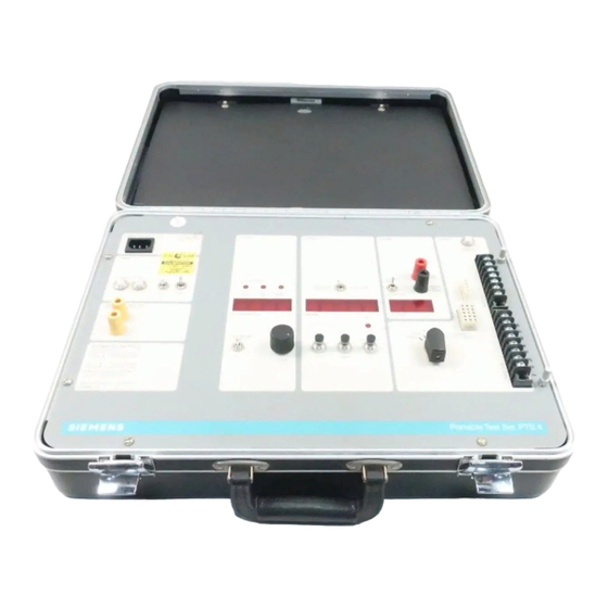
Description Description The test set pictured in Figures 1 and 2 show the Type PTS- 4 Portable Test Set and a typical test set-up. Rating Input—120 Volts, 50 or 60 Hz, 15 Amps Maximum. Output— 0 to 120 Volts, 15 Amps Maximum. Maximum continuous current on high scale 1.0 Amp. -
Page 5: Control Panel
Description Control Panel Arrangement See Figure 3. Input circuit breakers, 8 ampere thermal trip, manual reset. One circuit breaker is installed in each line of the incoming line cord. The circuit includes an air core current limiting reactor permanently included in each line to limit the available short circuit current. - Page 6 Description same in either case. This external connection may be 10. Seven Point Terminal Block. This terminal block is for useful when the incoming power is of poor quality so as convenience in bench testing STATIC TRIP II trip de- to affect the phase control circuitry of the test set.
- Page 7 Description device under test trips or when the STOP push button is operated. 18. Reset Switch. This switch resets the relay circuit and the stop clock. It also changes the time constant for the peak responding ammeter allowing the ammeter to return to zero in a shorter time.
-
Page 8: Testing Static Trip Iii Devices
Testing Static Trip III Devices NOTE Connections Keep 12t out, ZSI out, and thermal memory off Use Cord Set 18-732-184-508 Trip devices can be tested when mounted on a circuit Figure 4 shows how to connect the test set leads to the trip breaker in the disconnect position in its cubicle, with the device. - Page 9 Testing Static Trip III Devices POWER CONTROL in a clockwise direction. This is a five turn 5. Decreasing the current should cause the light to go out. control arranged for 50 Hz operation so a noticeable deadband is evident at zero output and 60 Hz. Increase the current until 6.
-
Page 10: Short Time Pick-Up Test
Testing Static Trip III Devices Set LONG TIME CURRENT SETTING on .5, LONG TIME NOTE BAND on 30, SHORT TIME PICK-UP 12X and INSTAN- The illumination of the “PICK-UP” light indicates that the TANEOUS PICK-UP ON 2X, ammeter on “All Other timed delay has started. -
Page 11: Short Time Delay Test
Testing Static Trip III Devices NOTE Bench Testing Static Trip III Devices When timing at values of current only slightly above pick-up, line voltage fluctuations may cause detriggering and result in Connections erroneous operating times. Therefore, it is advisable to watch With the static trip device away from the circuit breaker it is the long time pick-up light to note whether trigger voltage is necessary to make connections to the fanning strip of the trip... -
Page 12: Testing Static Trip Il Devices
Testing Static Trip III Devices The ZSI output is an isolated transistor that can be checked The output signal is a four bit, latched, parallel binary word with an ohmmeter, or by using a dropping resistor and representing the calculated RMS current in the highest phase connecting both the devices positive and negative power that is provided to the remote indicator. - Page 13 Testing Static Trip II Devices Trip devices can be tested when mounted on a circuit The following instructions cover testing of all the elements for breaker in the disconnect position in its cubicle, with the the most complicated type of trip device. Other types do not device on a circuit breaker removed from its cubicle or with contain all these elements.
-
Page 14: Testing Static Trip Device On Circuit Breaker
Testing Static Trip II Devices adjustable, and are calibrated in percent of the tripping Testing Static Trip Device on Circuit transformer rating as shown in the rating table. Breaker The long time element has 6 bands which are field CAUTION selectable. -
Page 15: Long Time Pick-Up Test
Testing Static Trip II Devices NOTE Short Time Pick-Up Test The illumination of the “PICK-UP” light indicates that the time Connect the yellow (TP-4) pin plug to the TP-4 terminal delay has started. If the current drops slightly, the light will go of the trip device, the black pin plug to TP-1, the green out, the timing circuit resets instantly and timing will start over plug to terminal 1, and the white plug to terminal 9. -
Page 16: Long Time Delay Test
Testing Static Trip II Devices Set LONG TIME PICK-UP on “A,” LONG TIME BAND on NOTE 6, SHORT TIME PICK-UP fully counter-clockwise, and When timing at values of current only slightly above pick-up, INSTANTANEOUS PICK-UP ON 3X line voltage fluctuations may cause detriggering and result in erroneous operating times. -
Page 17: Bench Testing Static Trip Ii Devices
Testing Static Trip II Devices Press the START button and adjust the current to 0.5 ampere or more. (Erroneous time delay readings and failure to trip the circuit breaker or target may occur at lower values of current. The waveshape of current from the test set may not provide enough power to charge the filter capacitor in the trip device before tripping occurs. -
Page 18: Testing First Generation Trip Devices
Testing First Generation Trip Devices models are listed and described . Figures 13, 14, 15, 16 and Connections— 17 are the time current characteristic curves for the various Use Cord Set 1 8-732-1 84-506 models. Connections from the test set are different for different models and are shown in Figures 9 through 12. -
Page 19: Test Procedures
Testing First Generation Trip Devices labeled “Instantaneous Trip Setting” (4). The Short Time Pick- Up is labeled “Transfer to Short Time (5). There are no test jacks provided on the front of the device. Connections for trigger indication are made to points on the terminal block as shown in Figures 9 through 12. -
Page 20: Bench Testing
Testing First Generation Trip Devices MODEL AG (optional)—provides phase overcurrent protec- Bench Testing tion plus sensitive ground fault overcurrent protection for systems with phase-to-phase loading. Ground current pick- The alligator clips described previously are also used to make up settings are independent of the phase pick-up settings, connections to the first generation trip devices for bench and continuously adjustable in the field from 20% through testing, so connections and procedures are the same as... -
Page 21: Testing Limitrip Devices
One core provides power to the trip device and the transformers on the back of the circuit breaker: To gain other provides the input signal. The PTS-4 test set is arranged access to these terminals, it is necessary to remove the circuit to provide both an input signal and power signal for test breaker from the cubicle. -
Page 22: Settings Of Bands And Pick-Ups
Testing Limitrip Devices Settings of Bands and Pick-Ups Test—Long Time Pick-Up PICK-UP and BAND settings are made by closing or opening t is not necessary to operate the circuit breaker during the trip switches grouped in DIP switch modules for the various device tests, the breaker can be left open. -
Page 23: Test-Short Time Pick-Up
Testing Limitrip Devices Test—Short Time Pick-Up Test—Long Time Delay Connect the Red GRABBER to the SHORT TIME PICK- Connect the test set to the device as described under UP test point. See Figure 18. the heading “Connections.” Connect the red GRABBER to the LONG TIME TEST POINT shown in Figure 18. -
Page 24: Test-Short Time Delay
Testing Limitrip Devices Test—Short Time Delay Bench Test—Limitrip Devices Connections to the device as described under the To bench test Limitrip devices, follow the same procedures heading “Connections.” The GRABBER connections are previously indicated for testing on the breaker. The following not needed adjustments in procedure and comments should be noted: (The alligator clips are used to connect the test set-cord-set... -
Page 25: Comments On Test Results
Comments on Test Results There are several things that can throw test results off so if results don’t agree with design values, it is best to verify that equipment and testing procedures are in order before draw- ing any conclusions. Recheck test connections to make sure that they are correct. -
Page 26: Testing The Tripping Actuator
Testing the Tripping Actuator If the device fails to trip the circuit breaker, the trouble may Bench Testing Actuators be in the tripping actuator. Set the selector switch to the “Actuator Test” position. Testing the Actuator on the Circuit Connect the red actuator lead to the red five-way binding post and the black actuator lead to the black Breaker five-way binding post. -
Page 27: Testing The Tripping Transformers
Testing the Tripping Transformers The tests described in the preceding sections verify perfor- Exciting Current Test mance of the static trip device and the actuator. An exciting current test can be run on the transformer. This The third link in the protection system is the circuit breaker is done by applying an AC voltage to the secondary winding mounted tripping transformers. - Page 28 Testing the Tripping Transformers Table 5. Static Trip II and First Generation Tripping Table 7. Static Trip II R L. Style Tripping Transformer Transformers Tripping Exciting Maximum Tripping Exciting Maximum Transformer Rating Voltage RMS Exciting Current Transformer Rating Voltage RMS Exciting Current 80:1 0.25...
-
Page 29: Repair Of Static Trip Devices
Therefore, if the tests described in these instruc- tions indicate that a static trip device or the test set itself is defective, contact your nearest Siemens representative for instructions on returning the unit to the factory or other authorized service facility for repair... - Page 30 Siemens Energy& Automation, Inc. Switchgear and Motor Control Business P.O. Box 29503 Raleigh, NC 27626 (919) 365-6660...
Need help?
Do you have a question about the PTS-4 and is the answer not in the manual?
Questions and answers