Table of Contents
Advertisement
Quick Links
Advertisement
Table of Contents

Subscribe to Our Youtube Channel
Related Manuals for Viega 8350.32


Summary of Contents for Viega 8350.32
- Page 1 Instructions for Use for concealed cistern 2L, combination with WC flush plates Visign for Public 2, Visign for Style 11, 12, and Visign for More 100, 102, 103 flush actuation via on-site potential-free contact Model Year built: 8350.32 from 05/2012 en_INT...
- Page 2 WC flush actuation 2 from 48...
-
Page 3: Table Of Contents
Table of contents Table of contents About these instructions for use Target groups Labelling of notes About this translated version Product information Standards and regulations Safety advice Intended use 2.3.1 Areas of use Product description 2.4.1 Overview 2.4.2 Technical data 2.4.3 Operating mode 2.4.4... -
Page 4: About These Instructions For Use
This restriction does not extend to possible operating instructions. The installation of Viega products must take place in accordance with the general rules of engineering and the Viega instructions for use. -
Page 5: About This Translated Version
About these instructions for use Notes give you additional helpful tips. About this translated version This instruction for use contains important information about the choice of product or system, assembly and commissioning as well as intended use and, if required, maintenance measures. The information about the products, their properties and application technology are based on the current standards in Europe (e. -
Page 6: Product Information
Standards and regulations The following standards and regulations apply to Germany / Europe. National regulations can be found on the relevant web site of your country at viega.com/standards. Regulations from section: Fields of application / Mounting conditions Scope / Notice Regulations applicable in Ger‐... - Page 7 Flushes can be actuated at certain times via the Hygiene+ function to prevent stagnation in the drinking water lines. Suitable cisterns Installation is only possible in the following Viega concealed cisterns: Cistern model 2H Cistern model 2L Ascertain which model is installed before mounting. The following infor‐...
-
Page 8: Product Description
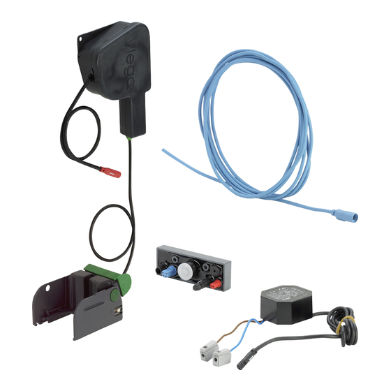
Product information Product range Name within the Model number product range Visign for Public 8327.1 Visign for Style 11, 12 8331.1, 8332.1, 8332.4 Visign for More 100, 102, 103, 104 8352.1, 8353.1, 8355.1, 8354.1 Product description 2.4.1 Overview Fig. 1: Scope of delivery Bowden cable unit holder for control (for cistern 2H) holder for control (for cistern 2L) -
Page 9: Technical Data
Product information 2.4.2 Technical data The product has the following technical data: Flush volume The flush volumes for the manual flush actuation are: Small flush volume: 3–4 litres Large flush volume: 6–9 litres The following flush volumes can be set for the electronic actuation: Large flush volume: 4.5 / 6 / 9 litres Small flush volume: 3 / 4 litres If the external sensor (e. -
Page 10: Operating Mode
Product information 2.4.3 Operating mode Electronic actuation of a flush Fig. 2: Actuation of the flush via an external sensor A signal is sent to control the flush actuation through an external sensor, e. g. a button or photo sensor. Fig. -
Page 11: System Expansions
Stagnation can lead to the build up of germs (e. g. legionella) in drinking water pipes. It is important to rinse the pipeline regularly to prevent the build up of bacteria. The Viega Hygiene+ function was developed for this reason. - Page 12 Product information Signals to actuate the flush (e. g. on support hinged handles) sent by HEWI radio transmitters can be received by the radio receiver model 8350.35. Additional external sensors Fig. 7: Connection of a second external button One requires the following accessories to be able to connect an addi‐ tional external sensor as shown: Multiple sensors can be connected at the same time using the exten‐...
- Page 13 Product information Additionally required: 1 connection cable sensitive. Buttons, switches or photo sensors for actuating the flush can be con‐ nected to the control on site via the connection cable sensitive model 8355.90. Additional radio controlled actuation Fig. 8: Connection of radio and cable sensors One requires the following accessories to be able to connect a radio controlled actuator alongside an external sensor as shown: Multiple sensors can be connected at the same time using the exten‐...
-
Page 14: Setting Options
Product information Signals to actuate the flush (e. g. on support hinged handles) sent by HEWI radio transmitters can be received by the radio receiver model 8350.35. Redundant power supply Fig. 9: Connection of the redundant power supply To create a redundant power supply with an additional battery compart‐ ment as shown, you will need the following accessories: The battery compartment can be connected for a redundant power supply using the adapter model 8355.91. -
Page 15: Accessories
Hygiene+ flush volume 9 litres Accessories Required accessories You require a flush plate so that the flush can be actuated directly at the WC. The Viega models that can be used are found at Ä „Suitable manual flush plates“ on page 7. Optional accessories Installation set The set model 8350.14 contains a hollow wall socket to house the... - Page 16 Product information Extension cable 2 metre cable model 8352.690 for the extension of the power supply to a maximum of 4.75 metres in length. Programming set This programming set is required to change the flush setting or activate the Hygiene+ function. It contains a connection cable with a program‐ ming contact and a magnetic pin.
-
Page 17: Handling
Handling 3 Handling Assembly information 3.1.1 Mounting conditions The model may only be used for the models mentioned in Ä Chapter 2.3.1 „Areas of use“ on page 6. Installation position of the power pack The power pack should be mounted in an easily accessible place to allow subsequent access. -
Page 18: Required Material And Tools
Handling Fig. 11: Protected zones According to the applicable regulations, installation of the power pack in the protected zones 0 and 1 of shower rooms and bathrooms is not per‐ mitted, see Ä „Regulations from section: Fields of application / Mounting conditions“... -
Page 19: Assembly
Handling Assembly 3.2.1 Mounting the power pack DANGER! Danger due to electrical current An electric shock can lead to burns and serious injury and even death. – Work on the electrics may only be carried out by trained electricians. – Always de-energise the connection line before work is commenced. -
Page 20: Preparing The Installation
Handling 3.2.2 Preparing the installation The following work stages and diagrams differ depending on the cistern being used. The relevant steps are marked accordingly. Requirements: The cistern is fitted into the pre-wall. If external sensors are to be connected, the cables must be laid through to the cistern. - Page 21 Handling Score the revision shaft along the edge of the tiles with a knife. Angle the knife to do this so that the cut is made flush to the surface of the wall. Cut the corners of the revision shaft vertically through to the wall surface.
- Page 22 Handling INFO! Only for assembly of the flush plate in cistern 2H or on the front of cistern 2L. Press the bow backwards from the mounting of the mechanism. INFO! Only for assembly of the flush plate on the top of cistern Press the bow backwards from the mounting of the mechanism.
-
Page 23: Mounting The Flush Actuation (Cistern 2H)
Handling INFO! Only with the cistern 2H. Remove and keep spacer. 3.2.3 Mounting the flush actuation (cistern 2H) Requirements: The revision shaft is shortened in such a way that it is flush with the upper edge of the tiles. Mechanism, bow and spacer are removed. Close corner valve. - Page 24 Handling Open the corner valve for a few seconds to rinse the pipe. Re-close corner valve. Mounting the drive unit Lead the panel into the cistern at an angle. Align the right side of the holding panel with the shaft frame of the cistern.
- Page 25 Handling Align the holding panel horizontally. The bow on the left side of the holding panel must be firmly posi‐ tioned between the vertical fins of the back wall. Push the drive unit onto the holding panel. The drive unit must be secure in the guiding rail. If the holding panel for the drive unit is mounted, remove holding panel.
- Page 26 Handling Mounting the holder for control Position the holder on the domes. Push rubber plugs onto the dome to secure the holder. Connecting the control Observation of the prescribed connection sequence is required. The power supply must always be connected last, to ensure that all of the connected components function.
- Page 27 Handling Connect the blue connection cable from the sensor to the blue con‐ nection of the control. Also observe section Ä Chapter 3.2.5 „Connecting external sen‐ sors“ on page 37. Connect the black cable of the power supply to the outer right con‐ nection of the control.
- Page 28 Handling Connect the flexible hose onto the filling valve. Open corner valve. Insert spacer. Mounting the battery compartment (optional) WC flush actuation 28 from 48...
- Page 29 Handling Push the holder for the battery compartment onto the spacer from the left. Push the battery compartment through the large opening into the holder. Push the battery compartment into the smaller opening. The battery compartment must be clicked into place directly behind the cover in the holder.
-
Page 30: Mounting The Flush Actuation (Cistern 2L)
Handling Insert mechanism. The mechanism must sit exactly in the recesses of the cistern. Turn the mechanism's lock by 90° in a clockwise direction. ð The mechanism is locked. As the next step, fitting of the flush plate as per the instruc‐ tion manual supplied. - Page 31 Handling Loosen flexible hose on the filling valve (size 19). Open the corner valve for a few seconds to rinse the pipe. Re-close corner valve. Mounting the drive unit If the holding panel is not mounted on the Bowden cable unit, posi‐ tion the holding panel.
- Page 32 Handling Place the drive unit onto the holding panel. Push the Bowden cable unit onto the drain valve from the left. The Bowden cable unit must be felt to click into place on the drain valve. Mounting the holder for control Position holder with recess on the corner valve.
- Page 33 Handling Push holder backwards until it clicks into place on the plug in the back wall. Connecting the control Observation of the prescribed connection sequence is required. The power supply must always be connected last, to ensure that all of the connected components function. INFO! Mounting is much easier if the plug is inserted into the control outside of the cistern.
- Page 34 Handling Connect the black cable of the power supply to the outer right con‐ nection of the control. INFO! Settings for the control can also already be made at this point. The programming set is easier to connect if the control is not yet installed in the cistern.
- Page 35 Handling Open corner valve. Mounting the battery compartment (optional) Place the battery compartment onto the control holder. If necessary, secure the battery compartment with a cable tie. Mounting the mechanism How to install the mechanism depends on whether the flush plate is to be fitted to the front or top of the cistern.
- Page 36 Handling Insert mechanism. The mechanism must sit exactly in the recesses of the cistern. Turn the mechanism's lock by 90° in a clockwise direction. ð The mechanism is locked. Horizontal installation (flush plate on the top of the cistern) Hang the mechanism in the bow of the drain valve. WC flush actuation 36 from 48...
-
Page 37: Connecting External Sensors
Handling Insert mechanism. In doing so, ensure that the tracks on the top and bottom edge of the mechanism are in the indentations in the revision shaft of the cistern. Turn the mechanism's lock by 90° in a clockwise direction. ð... - Page 38 Handling Requirements: Button with locking function or potential-free contact (closure time at least 350 ms) available Connection cable model 8355.90 available Connect the contact to actuate the small flush volume between the green (1) and yellow cable (3). Connect the contact to actuate the large flush volume between the green (1) and white cable (2).
-
Page 39: Commissioning
Handling Commissioning 3.3.1 Setting the flush Programming block Programming the control can be carried out for 30 minutes after the supply voltage is applied. The control returns to normal operation after 30 minutes – programming is now blocked. If the settings have to be changed after this time, the control must be disconnected from the power supply for at least 10 seconds. - Page 40 Handling Connect the cable of the programming contact to the control. Hold the magnetic key over the programming contact. ð In the following, signals sound to show which setting is active. Remove magnetic key to enable setting. The following values can be set by removing the magnetic key: Remove magnetic key after Setting 1st acoustic signal...
-
Page 41: Setting Hygiene+ Function
Handling Remove the cable of the programming contact. Place a protective cap onto the contact. 3.3.2 Setting Hygiene+ function The Hygiene+ function is deactivated when delivered. If you wish to use the Hygiene+ function, you must program the following settings. The flush volume for the Hygiene+ function can only be selected if the Hygiene+ function has been activated by choosing a flushing interval. - Page 42 Handling Setting the flush interval Requirements: The revision shaft is open and the control can be accessed. The control programming block is not active Ä „ Programming block “ on page 39. The programming set is available. Remove the protective cap of the programming connection from the control.
- Page 43 Handling Hold the magnetic key in front of the programming contact. ð In the following, signals sound to show which setting is active. Remove magnetic key to enable setting. The following values can be set by removing the magnetic key: Remove magnetic key after Setting 8th acoustic signal...
- Page 44 Handling Place a protective cap onto the contact. Setting Hygiene+ flush volume Requirements: The revision shaft is open and the control can be accessed. The control programming block is not active Ä „ Programming block “ on page 39. The programming set is available. The Hygiene+ interval is set.
- Page 45 Handling Connect the cable from the programming contact onto the control. Hold the magnetic key in front of the programming contact. ð In the following, signals sound to show which setting is active. Remove magnetic key to enable setting. The following values can be set by removing the magnetic key: Remove magnetic key after Setting 4th acoustic signal...
-
Page 46: Faults, Faults And Remedy
Handling Remove the cable of the programming contact. Place a protective cap onto the contact. Faults, faults and remedy Error Cause Remedy WC does not flush Power supply failure actuate manual flush Cistern is not yet completely full Wait until the cistern is sufficiently full No water in cistern, corner valve is Open corner valve... -
Page 47: Care And Maintenance
Handling Care and maintenance 3.5.1 Maintenance tips The flush actuation requires no care. When maintaining the flush plate, heed the instructions of the flush plate manual. 3.5.2 Replacing the battery Cistern 2L Only for use of a battery compartment for redundant power supply. -
Page 48: Disposal
Handling Insert new battery and close battery compartment. Place the battery compartment onto the control holder. If necessary, secure the battery compartment with a cable tie. Replace and lock mechanism. Mount flush plate according to manual. Disposal Separate the product and packaging materials (e. g. paper, metal, plastic or non-ferrous metals) and dispose of in accordance with valid national legal requirements.
Need help?
Do you have a question about the 8350.32 and is the answer not in the manual?
Questions and answers