
Related Manuals for Beckman Coulter Avanti J-HC


Summary of Contents for Beckman Coulter Avanti J-HC
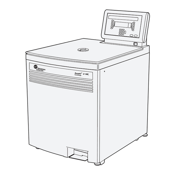
- Page 1 Instructions For Use Avanti J-HC High-Capacity Centrifuge PN J3HC-IM-5AD December 2016 Beckman Coulter, Inc. 250 S. Kraemer Blvd. Brea, CA 92821 U.S.A.
- Page 2 PN J3HC-IM-5AD (December 2016) © 2016 Beckman Coulter, Inc. All rights reserved Beckman Coulter, the stylized logo, and the Beckman Coulter product and service marks mentioned herein are trademarks or registered trademarks of Beckman Coulter, Inc. in the United States and other countries.
-
Page 3: Safety Notice
NOTE is used to call attention to notable information that should be followed during installation, use, or servicing of this equipment. Safety During Installation and/or Maintenance This centrifuge is designed to be installed by a Beckman Coulter field service representative. Installation by anyone other than authorized Beckman Coulter personnel invalidates any warranty covering the instrument. -
Page 4: Electrical Safety
Mechanical Safety For safe operation of the equipment, observe the following: • Use only the Beckman Coulter rotors and accessories designed for use in this centrifuge. • Do not exceed the maximum rated speed of the rotor in use. • NEVER attempt to slow or stop a rotor by hand. - Page 5 • Dispose of all waste solutions according to appropriate environmental health and safety guidelines. It is your responsibility to decontaminate the instrument and accessories before requesting service by Beckman Coulter Field Service. RoHS Notice These labels and materials declaration table (the Table of Hazardous Substance’s Name and Concentration) are to meet People’s Republic of China Electronic Industry Standard SJ/T11364-2006...
- Page 6 Safety Notice RoHS Notice PN J3HC-IM-5AD...
-
Page 7: Table Of Contents
Contents Safety Notice, iii Alerts for Warning, Caution, Important, and Note, iii Safety During Installation and/or Maintenance, iii Electrical Safety, iv Safety Against Risk of Fire, iv Mechanical Safety, iv Chemical and Biological Safety, iv RoHS Notice, v Introduction, xiii Certification, xiii Scope of Manual, xiii... - Page 8 Contents Specifications, 1-8 Available Rotors, 1-10 CHAPTER 2: Operation, 2-1 Introduction, 2-1 Summary of Avanti J-HC Run Procedures, 2-1 Manual Run, 2-1 Programmed Run, 2-2 Preparation, 2-3 Installing the Rotor, 2-4 Manual Operation, 2-4 Selecting a Rotor, 2-5 Entering Run...
- Page 9 Additional Requirements for Three-Phase Power Connections, A-3 Space Requirements, A-4 Securing the Centrifuge to the Floor, A-6 Using the JA-10 Rotor, A-6 Checking for Rotor Pins, A-6 APPENDIX B: Temperature Calibration Procedure, B-1 Description, B-1 Beckman Coulter, Inc. Avanti J-HC Centrifuge Warranty Related Documents...
- Page 10 Venting the Chamber Vacuum, 3-7 Front Panel Retaining Strip, 3-9 Avanti J-HC Single-Phase Power Connections, A-2 Avanti J-HC Three-Phase “Y” Power Connections, A-3 Correct and Incorrect Three-Phase Power Configurations, A-4 Rear View and Dimensions, A-5 Checking the Rotor for Drive...
- Page 11 Tables Tables Complete and Abbreviated Rotor Names, 1-6 Available Rotors for the Avanti J-HC Centrifuge, 1-11 Acceleration and Deceleration Settings, 2-11 Diagnostic Message Chart, 3-2 Nominal Supply Voltage Ratings for the Avanti J-HC, A-2 Required Wire Connections, A-3...
- Page 12 Tables...
-
Page 13: Introduction
Beckman Coulter rotors). Declarations of conformity and certificates of compliance are available at www.beckmancoulter.com. Scope of Manual This manual is designed to familiarize you with the Avanti J-HC centrifuge, its functions, specifications, operation, and routine operator care and maintenance. Beckman Coulter recommends that you read this entire manual, especially the... -
Page 14: Recycling Label
For Beckman Coulter products bearing this label please contact your dealer or local Beckman Coulter office for details on the take back program that will facilitate the proper collection, treatment, recovery, recycling and safe disposal of the device. - Page 15 Introduction Multi Compliance Label • The RCM mark is intended for use on products that comply with Australian communications Media Authority (ACMA) EMC Requirements. PN J3HC-IM-5AD...
- Page 16 Introduction Multi Compliance Label PN J3HC-IM-5AD...
-
Page 17: Description
Contact your Beckman Coulter representative for more information. Safety Features Avanti J-HC centrifuges have been designed and tested to operate safely indoors at altitudes up to 2000 m (6252 ft). * Avanti J-HC software and firmware copyright 1999–2013 by Beckman Coulter, Inc., Brea, CA, 92821, U.S.A. -
Page 18: Centrifuge Chassis
• A steel casing surrounds the rotor chamber to provide operator protection in the unlikely event of a rotor mishap. • An automatic rotor identification system detects which Beckman Coulter rotor is installed in the centrifuge during acceleration and prevents the rotor from running above its maximum rated speed. -
Page 19: Rotor Chamber
Description Centrifuge Chassis Rotor Chamber The rotor chamber is made of stainless steel to resist corrosion. The rotor drive hub and thermistor are visible in the bottom of the chamber. A rubber gasket around the chamber opening ensures sealing. (Instrument gaskets have not been qualified as bioseals for aerosol containment.) A port in the centrifuge door provides visual access to the chamber, enabling verification of rotor speed using a customer-supplied strobe system. -
Page 20: Drive
The name rating plate is affixed to the rear of the centrifuge. Check that the line voltage agrees with the voltage listed on this name rating plate before connecting the centrifuge. Always mention the model number and serial number when corresponding with Beckman Coulter regarding your centrifuge. -
Page 21: The Control Panel
Description Controls and Indicators Figure 1.1 The Control Panel HOLD 1. Actual Value Display Actual Value Display The actual value display (Figure 1.2) indicates the actual centrifuge operating conditions. Figure 1.2 Actual Value Display ROTOR ID SPEED TIME TEMP RPM/RCF HR:MIN ROTOR ID Indicates the installed rotor (see... -
Page 22: The Setup Screen
(JA: fixed angle rotors; JS: swinging bucket rotors; JLA: lightweight fixed angle rotors). Pressing a rotor type soft key displays a list of the rotors of that type that can be used in the Avanti J-HC. (Abbreviated rotor names are displayed.) SPEED Pressed to enter a run speed, in RPM or RCF ... -
Page 23: Keypad
Description Controls and Indicators TIME Pressed to enter run time (using the keypad). When TIME is pressed, the three time mode soft keys are displayed: HH:MM (hour:minute), G-SEC (g-seconds), and HOLD. Pressing any of the soft keys causes the TIME display to flash, indicating that a time can be entered on the keypad. •... -
Page 24: System Keys
Description Specifications (clear entry) key clears any parameter in the active field. Pressing will also clear some diagnostic messages. If a diagnostic message does not clear when is pressed, see CHAPTER 3, Troubleshooting. System Keys START Pressing ENTER then START begins the run. (START must be pressed within 5 seconds of pressing ENTER.) This key combination can also be used to abort a deceleration process and restart the centrifuge. - Page 25 Description Specifications Specification Description Temperature • Set temperature — –10 to +40°C in 1°C increments • Temperature control — 2°C of set temperature (from 1000 to 10,000 RPM) • Temperature display — actual rotor temperature in1°C increments • Ambient temperature range —...
-
Page 26: Available Rotors
Only the Beckman Coulter rotors listed in Table 1.2 can be used in the Avanti J-HC centrifuge. The rotors are described in individual manuals shipped with each rotor. Information on rotors and accessories is also available in Rotors and Tubes for J Series Centrifuges (JR-IM) and in the High Performance, High Capacity Rotors, Tubes and Accessories Catalog (BR-8102). - Page 27 Customers purchasing a new JS-4.2 rotor for use in the Avanti J-HC must also purchase Tie Down Kit (367045). c. The microplate carriers (358682) available for use in the JS-4.2 rotor cannot be used in the Avanti J-HC. Round buckets (368575) must be used when these rotors are run in this centrifuge.
- Page 28 Description Available Rotors 1-12 PN J3HC-IM-5AD...
-
Page 29: Chapter 2: Operation
Do not lean on the centrifuge or place items on it while it is operating. Summary of Avanti J-HC Run Procedures For runs at other than room temperature, precool or prewarm the rotor to the required temperature before the run. -
Page 30: Programmed Run
Operation Summary of Avanti J-HC Run Procedures Install the rotor according to instructions in the applicable rotor manual, then firmly close the chamber door. Press ROTOR , press the soft key to select rotor type, press the soft key to select the rotor name. -
Page 31: Preparation
Operation Preparation Press then use the keypad to enter the program number. ENTER STOP. Check that all parameters are correct and that the door is closed. Press , then press STOP Wait for program step 1 or 2 to end, or end the run by pressing When the rotor stops, depress the foot pedal to open the chamber door. -
Page 32: Installing The Rotor
Operation Manual Operation Installing the Rotor The power must be turned on before you can unlock and open the chamber door. Turn the power switch on ( Indicator lights on the control panel light up. Depress the foot pedal to open the door. The door opens. -
Page 33: Selecting A Rotor
Operation Manual Operation • If an invalid setting is entered, the display blinks and the valid range for that parameter is ENTER displayed in the message line. A valid parameter must be entered and must be pressed before you can enter another parameter. Selecting a Rotor Press ROTOR. - Page 34 Operation Manual Operation Entering RPM Press SPEED Speed: field flashes, and soft keys appear. indicator illuminates in the actual value display. ROTOR ID SPEED TIME TEMP RPM/RCF HR:MIN °C Rotor : JS-5.0 Speed : -- -- x G Time : 00:00 Temp : 25°C Max Temp : 29°C...
-
Page 35: Entering Run Time
Operation Manual Operation = - - field flashes. Enter the required RCF on the keypad and press ENTER. • The RCF and the corresponding RPM appear in the Speed: field. • The RCF ( g) indicator illuminates on the actual value display, indicating that RCF ( g) is being displayed during the run. - Page 36 Operation Manual Operation Entered time appears in the Time: field. HH:MM Rotor : - - G-SEC Speed : 5,000 7,480 x G HOLD Time : 00:20 g-sec = 2.93E09 Temp : 25°C Max Temp : 29°C Accel : MAX Decel : MAX Press the next function key or press ENTER , then...
- Page 37 Operation Manual Operation • If you enter a value out of the achievable g-seconds range for that rotor, a message prompts you to enter a different value. ENTER START Press the next function key or press then • The centrifuge begins calculating and displaying the accumulated force. •...
-
Page 38: Entering Run Temperature
Operation Manual Operation ENTER START. Press the next function key or press , then HOLD TIME After you start the run, the indicator illuminates in the display. STOP The elapsed run time is displayed. The run continues until is pressed. Entering Run Temperature Run temperature can be set from –10 to +40°C. -
Page 39: Entering Acceleration And Deceleration Times
Operation Manual Operation Your selection ( ) appears to the right of the Max Temp: field. Rotor : JS-5.0 Speed : 5,000 Time : 00:00 Temp : 20°C Max Temp : 24°C - YES Accel : MAX Decel : MAX Overtemp shutdown active? YES or NO Entering Acceleration and Deceleration Times The centrifuge provides a choice of two acceleration rates (one for ARIES rotors) and four... -
Page 40: Starting A Run
Operation Manual Operation a. If you choose TIME , enter an acceleration time from 1 to 10 minutes, or accept the 10-minute default setting, and press again. Deceleration Accel: Press twice (if the cursor is in the field, press once). Decel: field flashes. -
Page 41: Changing Parameters During A Run
Operation Programmed Operation Changing Parameters During a Run While a run is in progress, run parameters (speed, time, temperature, and acceleration and deceleration settings) can be changed without stopping the run by entering the new setting and ENTER. pressing Ending a Run To end a run in progress, press STOP STOP... - Page 42 Operation Programmed Operation b. If you enter a number that is already assigned to a program, you can either overwrite the program or select another program number. Rotor : --- STEP1 Speed : --- STEP2 Time : 00:00 SAVE Temp : 20 Max Temp : 24 - EXIT Accel : MAX...
-
Page 43: Modifying A Program
Operation Programmed Operation b. To recheck the parameters in either step, press the STEP1 STEP2 soft key to toggle to that step. Rotor : JS-5.0 STEP1 Speed : 5,000 RPM = 7,480 x G STEP2 Time : 00:20 SAVE Temp : 20 Max Temp : 24 - YES EXIT Accel : MAX... -
Page 44: Running A Program
Operation Programmed Operation STEP2 To see step 2 parameters, press the soft key. The step 2 parameters appear. Modify the parameters for either step. The newly entered parameters appear. ENTER Press when done. b. Repeat for the other step, if required. Press the SAVE soft key to save both program steps. - Page 45 Operation Programmed Operation ENTER START Press , then 2-17 PN J3HC-IM-5AD...
- Page 46 Operation Programmed Operation 2-18 PN J3HC-IM-5AD...
-
Page 47: Chapter 3: Troubleshooting
Maintenance. For any problems not covered here, call Beckman Coulter Customer Field Service (1-800-742-2345 in the United States for assistance; outside the U.S. contact your local Beckman Coulter office or visit us on the web at www.beckmancoulter.com). NOTE It is your responsibility to decontaminate the instrument, as well as any rotors and accessories, before requesting service by Beckman Coulter Field Service. - Page 48 Press CE and try to restart the run. If this does Foot pedal was Latches are not Door problem, refer depressed before end operating properly not work, call Beckman Coulter Field Service. to manual of run Door problem, refer to manual Door stays locked after Sample cannot be Restart the centrifuge and perform a brief run.
- Page 49 The system cannot System shuts down Dynamic rotor ID not verify the installed rotor with brake run in the Avanti J-HC (see Table 1.2). found, Not BII rotor — Enter the rotor name on the control panel and restart the run. If you are running the JS-4.2 rotor, make sure to select the...
-
Page 50: Accessing The Rotor In Case Of Power Failure
Call Beckman Coulter Field Service. FRS failure, refer to with maximum brake manual a. In the United States call 1-800-742-2345. Outside the United States, contact your local Beckman Coulter office. b. Friction Reduction System. Accessing the Rotor in Case of Power Failure WARNING Any maintenance procedure requiring removal of a panel exposes the operator to the possibility of electrical shock and/or mechanical injury. -
Page 51: Emergency Door Release Latch Access
Troubleshooting Accessing the Rotor in Case of Power Failure To access the door-locking mechanism, you must remove the instrument front panel. Two latches secure the front panel in place; these latches are accessible through two holes at the upper right and left of the panel (see Figure 3.1). -
Page 52: Manual Door Release
Troubleshooting Accessing the Rotor in Case of Power Failure Figure 3.2 Manual Door Release 1. Inner Front Panel 3. Manual Door Release Interlock Lever 2. Retaining Strip Pull the interlock lever out and left (at about a 45-degree angle), and while holding it out, step on the foot pedal. -
Page 53: Venting The Chamber Vacuum
Troubleshooting Accessing the Rotor in Case of Power Failure To vent the chamber vacuum, grasp the red rubber hose and pull it up until it comes off of the pump fitting (see Figure 3.3). a. Use a back-and-forth motion as you pull; this takes quite a bit of force. The vacuum will be completely vented several seconds after the hose is detached. - Page 54 Troubleshooting Accessing the Rotor in Case of Power Failure 1. Grasp red hose and pull up. Do not disconnect 3. Red hose removed from fitting the tubing lines tied to the red hose. 4. Replace hose 2. Vacuum Pump Replace the hose by pushing it down over the fitting as far as it can go. Pull the interlock lever out and left, and while holding it out, step on the foot pedal.
-
Page 55: Front Panel Retaining Strip
Troubleshooting Accessing the Rotor in Case of Power Failure Figure 3.4 Front Panel Retaining Strip 1. Retaining Strip PN J3HC-IM-5AD... - Page 56 Troubleshooting Accessing the Rotor in Case of Power Failure 3-10 PN J3HC-IM-5AD...
-
Page 57: Chapter 4: Care And Maintenance
Inspect the centrifuge chamber for accumulations of sample, dust, or glass particles from broken sample tubes. Clean as required (see Cleaning, below). Check the air filter on the back panel for obstructions. Keep vents clear and clean. * Call 1-800-742-2345 (U.S.A. or Canada) or contact your local Beckman Coulter office. PN J3HC-IM-5AD... -
Page 58: Cleaning
Care and Maintenance Maintenance Wipe condensation out of the rotor chamber between runs with a sponge or clean cloth to prevent chamber icing. Cleaning Clean the centrifuge frequently. Always clean up spills when they occur to prevent corrosives or contaminants from drying on component surfaces. NOTE Before using any cleaning or decontamination methods except those recommended by the manufacture, users should check with the manufacturer that the proposed method will not damage the... -
Page 59: Decontamination
Ethanol is a flammability hazard. Do not use it in or near operating centrifuges. While Beckman Coulter has tested ethanol (70%) and found that it does not damage the centrifuge, no guarantee of sterility or disinfection is expressed or implied. When sterilization or disinfection is a concern, consult your laboratory safety officer regarding proper methods to use. -
Page 60: Circuit Breaker And Fuses
Then set the bottom edge down. Circuit Breaker and Fuses There are no user-replaceable fuses in the Avanti J-HC centrifuge. If the centrifuge circuit breaker trips for any reason, the power switch will move to the OFF ( position. -
Page 61: Speed Calibration
Reset the circuit breaker by turning the power switch back to the ON ( ) position. a. If it trips again immediately, do not reset it. Call Beckman Coulter Field Service. CAUTION Repeated attempts to reset the centrifuge circuit breaker can cause substantial damage to electrical and electronic components. -
Page 62: Storage And Transport
Storage and Transport Storage To ensure that the centrifuge does not get damaged, contact Beckman Coulter Field Service for specific instructions and/or assistance in preparing the equipment for transport or long-term storage. Temperature and humidity conditions for storage should meet the environmental... -
Page 63: Replacement Parts And Supplies
Care and Maintenance Supply List Replacement Parts and Supplies NOTE For MSDS information, go to the Beckman Coulter website at www.beckmancoulter.com. Description Part Number Air filter 885218 Solution 555 (1 qt) 339555 PN J3HC-IM-5AD... - Page 64 Care and Maintenance Supply List PN J3HC-IM-5AD...
-
Page 65: Appendix A: Preinstallation Requirements
Beckman Coulter personnel invalidates any warranty covering the instrument. Site Preparation Requirements The Avanti J-HC centrifuge will be installed by a Beckman Coulter Field Service representative after preinstallation requirements for power and site preparation have been met. The following equipment is required for preinstallation: •... -
Page 66: Single- And Three-Phase Power Connections
Preinstallation Requirements Electrical Requirements Table A.1 Nominal Supply Voltage Ratings for the Avanti J-HC Nominal Instrument Instrument Nominal Supply Power Cord and Plug Voltage Rating Part Number Frequency Description Single-phase, 200/208/240 V 367501 185–264 V, permanently attached three- 50/60 Hz, 30 A... -
Page 67: Additional Requirements For Three-Phase Power Connections
Preinstallation Requirements Electrical Requirements Figure A.2 Avanti J-HC Three-Phase “Y” Power Connections 1. Measured Line Voltage Phase to Phase 3. Neutral 2. 16-ampere Circuit Breaker 4. Earth-Ground Table A.2 Required Wire Connections Wire Insulation Color Terminal Symbol Harmonized North American... -
Page 68: Space Requirements
Preinstallation Requirements Space Requirements WARNING To reduce the risk of electrical shock, this equipment uses a three-wire or five-wire electrical cord and plug to connect the centrifuge to earth-ground. To preserve this safety feature, make sure that the matching wall outlet receptacle is properly wired and earth-grounded. -
Page 69: Rear View And Dimensions
Preinstallation Requirements Space Requirements The centrifuge must have adequate air ventilation to ensure compliance to local requirements for vapors produced during centrifuge operation. Position the centrifuge so that the air diverter, shown in Figure A.4, touches the wall behind the centrifuge. -
Page 70: Securing The Centrifuge To The Floor
To check for drive pins, hold the rotor up or turn it on its side and look into the drive hole. b. If you do not see two metal pins in the hole, call your local Beckman Coulter office for information on returning the rotor to the factory for upgrading. -
Page 71: Checking The Rotor For Drive Pins
Preinstallation Requirements Using the JA-10 Rotor Figure A.5 Checking the Rotor for Drive Pins 1. Rotor Drive Hole 3. Avanti J Centrifuge Drive Spindle Hub 2. Drive Pins (may be horizontal, vertical, or angled) PN J3HC-IM-5AD... - Page 72 Preinstallation Requirements Using the JA-10 Rotor PN J3HC-IM-5AD...
-
Page 73: Appendix B: Temperature Calibration Procedure
Temperature Calibration Procedure Description The Avanti J-HC centrifuge specification for temperature control is 2°C of the set temperature. That means that your sample will stay within 2°C of set temperature at all times, after rotor and system equilibration, described below. (During transient conditions, such as acceleration and deceleration, the rotor temperatures may be outside this range.) The following procedure is... - Page 74 Temperature Calibration Procedure Description For example: If the required sample And the measured Set the temperature to temperature is buffer/water temperature 4°C 6°C 2°C 5°C 4°C 6°C PN J3HC-IM-5AD...
-
Page 75: Beckman Coulter, Inc
Beckman Coulter, or unless such repair in the sole opinion of Beckman Coulter is minor, or unless such modification is merely the installation of a new Beckman Coulter plug-in component for such product. - Page 76 Beckman Coulter, Inc. Avanti J-HC Centrifuge Warranty Warranty-2 PN J3HC-IM-5AD...
- Page 77 English / Deutsch / Español / Français / Italiano / Portugués / Русский / 中文 / 日本語 / 한국어 Symbol Simbole Symbol символ Simbolo Title / Titel / Titulo / Titre / Titolo / Titulo / Название / 标题 / タイトル / 제목 符号...
-
Page 80: Related Documents
Related Documents Rotors and Tubes For Beckman Coulter J2, J6, Avanti J Series Centrifuges PN JR-IM-10 • Rotors • Tubes, Bottles, and Accessories • Using Fixed-Angle Rotors • Using Swinging-Bucket Rotors • Using Vertical-Tube and Rack-Type Rotors • Care and Maintenance •...
Need help?
Do you have a question about the Avanti J-HC and is the answer not in the manual?
Questions and answers