
Related Manuals for Beckman Coulter Airfuge


Summary of Contents for Beckman Coulter Airfuge
- Page 1 Instruction For Use Airfuge Air Driven Ultracentrifuge AF-IM-13AC June 2020 Beckman Coulter, Inc. 250 S. Kraemer Blvd. Brea, CA 92821 U.S.A.
- Page 2 Beckman Coulter, the stylized logo, and the Beckman Coulter product and service marks mentioned herein are trademarks or registered trademarks of Beckman Coulter, Inc. in the United States and other countries. All other trademarks, service marks, products, or services are trademarks or registered trademarks of their respective holders.
-
Page 3: Revision History
Revision History For updates, go to www.beckman.com/techdocs and download the most recent manual or system help for your instrument. Issue AA, 03/2017 Changes or additions were made to: California Prop 65 Statement; Multi Compliance Label; Supplies. Issue AB, 08/2017 Changes or additions were made to: RoHS Caution. Issue AC, 06/2020 Changes or additions were made to: Beckman website for information search and customer support. - Page 4 Revision History AF-IM-13AC...
-
Page 5: Safety Notice
Safety Notice Read all product manuals and consult with Beckman Coulter-trained personnel before attempting to operate instrument. Do not attempt to perform any procedure before carefully reading all instructions. Always follow product labeling and manufacturer’s recommendations. If in doubt as... -
Page 6: Electrical Safety
Safety Notice Electrical Safety Electrical Safety To prevent electrically related injuries and property damage, properly inspect all electrical equipment prior to use and immediately report any electrical deficiencies. Contact a Beckman Coulter Representative for any servicing of equipment requiring the removal of covers or panels. Do not place containers holding liquid on or near the chamber door. -
Page 7: Safety Against Risk Of Fire
Safety Notice Safety Against Risk of Fire Safety Against Risk of Fire Fuses protect certain electrical circuits within this instrument against overcurrent conditions. For continued protection against the risk of fire, replace only with the same type and rating specified. WARNING Risk of personal injury or equipment damage. -
Page 8: Chemical And Biological Safety
• Dispose of all waste solutions according to appropriate environmental health and safety guidelines. It is your responsibility to decontaminate the instrument and accessories before requesting service by a Beckman Coulter representative. California Prop 65 Statement WARNING This product may contain a chemical known to the State of California to cause cancer, or birth defects or other reproductive harm. -
Page 9: Table Of Contents
Contents Revision History, iii Safety Notice, v Alerts for Danger, Warning, Caution, and Note, v Safety During Installation and/or Maintenance, v Electrical Safety, vi Safety Against Risk of Fire, vii Mechanical Safety, vii Chemical and Biological Safety, viii Introduction, xv Certification, xv Scope of Manual, xv... - Page 10 Requirements, 2-1 Electrical Requirements, 2-1 Installation Procedures, 2-2 Filter Installation, 2-2 Time-Delay Setting Check, 2-3 Leveling the Airfuge, 2-4 Installing the Brake Pin and Stator Pad, 2-5 Trial Run, 2-6 Cold Room Installation, 2-6 CHAPTER 3: Operation, 3-1 Introduction, 3-1...
- Page 11 Contents Storage and Transportation, 5-12 Supplies, 5-12 Warranty for the Airfuge Ultracentrifuge...
- Page 12 Panel, 1-3 Cross-section View of the Airfuge, 1-4 Rear View, 1-4 Airfuge Components and Accessories, 1-5 Filter Installation, 2-3 Aligning the Brake Pin in the Stator: The slot on the end of the pin straddles the brake spring wire. The broken line shows the wire direction (aligned with the screws).
- Page 13 Tables Tables Specifications, 1-6 Troubleshooting, 4-1 xiii...
- Page 14 Tables...
-
Page 15: Introduction
Further, the use of any equipment other than that recommended by Beckman Coulter has not been evaluated for safety. Use of any equipment not specifically recommended in this manual and/or the appropriate rotor manual is the sole responsibility of the user. -
Page 16: Radio Interference
2. the device is not to be disposed via the municipal waste collection system of any member state of the European Union. It is very important that customers understand and follow all laws regarding the proper decontamination and safe disposal of electrical equipment. For Beckman Coulter products bearing this label please contact us for details on the take back program that will facilitate the proper collection, treatment, recovery, recycling and safe disposal of the device. -
Page 17: Multi Compliance Label
Introduction Multi Compliance Label Multi Compliance Label • Recycling — Refer to the Recycling Label section in this document. — A “CE” mark indicates that a product has been assessed before being placed on the • market, and has been found to meet European Union safety, health, and/or environmental protection requirements. - Page 18 Introduction RoHS Caution xviii AF-IM-13AC...
-
Page 19: Description
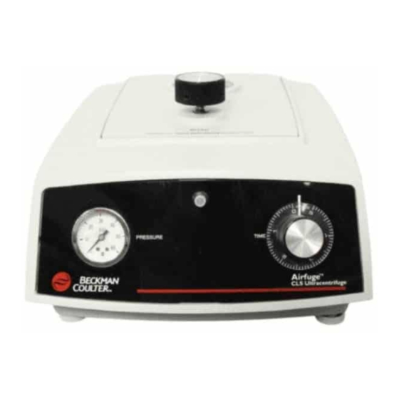
CHAPTER 1 Description Functional Description The Beckman Coulter Airfuge (see Figure 1.1) is a benchtop air-driven ultracentrifuge capable of accelerating rotors up to 110 000 rpm (revolutions per minute) in as little as 30 seconds. The instrument uses no vacuum or high-speed bearings; the rotor is supported and turned by streams of air. -
Page 20: Safety Features
The Airfuge ultracentrifuge has been designed and tested to operate safely indoors at altitudes up to 2 000 m (6 562 ft). The Airfuge is an exceptionally safe ultracentrifuge because the rotor is held in place by a pressure differential created during centrifugation. An air pressure limitation of 35 psig (240 kPa) is factory set. -
Page 21: Time-Delay Knob
Description Controls and Indicators Time-Delay Knob This knob, located on the ultracentrifuge bottom panel (see Figure 1.2), is used to set a time-delay period that allows the rotor to coast after the timer reaches zero at the end of a run. The run light goes out and a brake pin is released at the end of the set delay period. -
Page 22: Brake Tension Screw
Occasional adjustment of the spring tension, using the adjusting screw located on BRAKE TENSION the back panel (see Figure 1.4), may be necessary. Figure 1.3 Cross-section View of the Airfuge 1. Protective Window 6. Electromagnet 2. Turbine Flutes 7. Brake Spring Wire 3. Stator 8. -
Page 23: Levitation Air Screw
The black stator pad (see Figure 1.5) rests on the channel of the stator and cushions the rotor during a run and when the rotor is at rest. Figure 1.5 Airfuge Components and Accessories 1. Stator Pad 3. Brake Pin 2. Level... -
Page 24: Brake Pin
Name Rating Plate A name rating plate is affixed to the rear of the instrument. Always mention the serial number and model number when contacting Beckman Coulter regarding your Airfuge ultracentrifuge. Specifications Only values with tolerances or limits are guaranteed data. Values without tolerances are informative data, without guarantee. - Page 25 Description Specifications Table 1.1 Specifications (Continued) Specification Description Air pressure • Air pressure at ultracentrifuge for routine operation — 30 psig (207 kPa) • Air pressure at filter for routine operation — 42 psig (290 kPa) • Air pressure drop across filter —...
-
Page 26: Available Rotors
Available Rotors Airfuge rotors are made of anodized aluminum and have turbine flutes on the bottom that provide the driving surface for the jets of air. Pressurized air impinges on the rotor bottom and lifts and turns the rotor. A white plastic bushing fitted in the rotor bottom is engaged by the brake pin during braking. -
Page 27: Chapter 2: Installation
100 or 200–240 VAC To reduce the risk of electrical shock, this ultracentrifuge uses a three-wire electrical cord and plug to connect the ultracentrifuge to earth-ground. (Contact your local Beckman Coulter office for specific information regarding local requirements.) To preserve this safety feature: Make sure that the matching wall outlet receptacle is properly wired and earth-grounded. -
Page 28: Installation Procedures
Installation Installation Procedures Never use a two-wire extension cord or a two-wire non-grounding type of multiple-outlet receptacle strip. If there is any question about voltage, have a qualified service person measure it under load while the drive is operating. To ensure safety the ultracentrifuge should be wired to a remote emergency switch (preferably outside the room where the ultracentrifuge is housed, or adjacent to the exit from that room), in order to disconnect the ultracentrifuge from the main power source in case of a malfunction. -
Page 29: Time-Delay Setting Check
Installation Installation Procedures 1. Filter Bottom Figure 2.1 Filter Installation , mount the filter on a ring stand or on the wall. If non-rigid piping leads from the air source Clamp the filter to a ring stand, or use the supplied mounting brackets (see Figure 2-1) to mount the filter to the wall. -
Page 30: Leveling The Airfuge
Installation Installation Procedures Leveling the Airfuge The Airfuge must be leveled before use. Place the supplied liquid level on the center of the stator. Adjust the instrument front feet until the bubble of the level is centered. AF-IM-13AC... -
Page 31: Installing The Brake Pin And Stator Pad
Installation Installation Procedures Installing the Brake Pin and Stator Pad Place the brake pin in the hole at the center of the stator (see Figure 2.2). a. Make sure that the slot in the pin bottom straddles the brake spring wire as shown in the figure. -
Page 32: Trial Run
CHAPTER 5 for adjustment procedures. Cold Room Installation If rotor temperatures below room temperature are required, the Airfuge can be operated in a cold room. A typical cold room set-up is shown in Figure 2.3. In addition to the installation procedures above, the following variations are required. -
Page 33: Cold Room Setup
Installation Installation Procedures Approximately 3 m (10 ft) of finned copper tubing (3/8-in. ID recommended) must be added to the air supply line (see Figure 2.3) to allow the air to cool to cold-room temperature. • The operating temperature of the instrument will be a few degrees higher than the cold- room temperature;... - Page 34 Installation Installation Procedures AF-IM-13AC...
-
Page 35: Chapter 3: Operation
CHAPTER 3 Operation Introduction Refer to individual rotor manuals for detailed information on each rotor. WARNING Normal operation may involve the use of solutions and test samples that are pathogenic, toxic, or radioactive. Handle body fluids with care because they can transmit disease. - Page 36 NOTE If you are using an Airfuge with the digital speed readout accessory installed, use a flat black marker to color half of the rotor lid or cap flat black. If the black surface is shiny, inaccurate speed readings will be displayed.
-
Page 37: Worn And New Stator Pads
Operation Starting the Run Figure 3.1 Worn and New Stator Pads 1. Worn Stator Pads 2. New Stator Pads Place the rotor on the stator pad and shut the instrument door. Set the dial for the required run time. TIME •... -
Page 38: Ending The Run
Operation Ending the Run CAUTION If the rotor makes an unusual noise, turn the timer to zero. When the rotor stops, open the chamber door and remove the rotor. Check to make sure the rotor is loaded correctly. Correct the problem before restarting the run (see Table 4.1). -
Page 39: Chapter 4: Troubleshooting
NOTE It is your responsibility to decontaminate the instrument, as well as any rotors and/or accessories, before requesting service by Beckman Coulter Field Service representatives. Possible malfunctions are described in Table 4.1, along with possible causes—listed in the probable order of occurrence—and corrective actions. - Page 40 Light burned out Replace the lamp. Circuit breaker tripped Reset the circuit breaker. Time delay faulty Call Beckman Coulter Field Service. Rotor crashes Stator pad worn Order Repair Kit 1. Missing rotor lid or cap Refer to the applicable rotor manual.
-
Page 41: Chapter 5: Maintenance
Instrument Care NOTE It is your responsibility to decontaminate the instrument, as well as any rotors and/or accessories, before requesting service by Beckman Coulter Field Service representatives. WARNING Any maintenance procedure requiring removal of a panel exposes the operator to the possibility of electrical shock and/or mechanical injury. -
Page 42: Cleaning
Maintenance Cleaning Regularly check the stator pad for wear; a worn pad is smooth and shiny on the upper half of the inside surface. • A shiny pad has lost its cushioning effect and will eventually cause rotor failure. a. Replace a worn pad. NOTE Proper deceleration of the rotor (that is, allowing the rotor to come to a complete stop before opening the door) will increase pad life. -
Page 43: Prying Up The Stator
Maintenance Cleaning WARNING Disconnect the power cord and the air supply. Disconnect the air supply at the rear of the instrument by pulling back the quick-disconnect hose sleeve. • The hose may be disconnected while it is under pressure, but be careful not to damage surrounding objects. -
Page 44: Lifting Out The Stator. Keep The Stator Level To Prevent Binding
Maintenance Cleaning Figure 5.2 Lifting Out the Stator. Keep the stator level to prevent binding. Remove the three stator O-rings, shown in Figure 5.3. Use a pointed wooden or plastic tool to avoid scratching the stator. Figure 5.3 Stator O-Ring Positions AF-IM-13AC... -
Page 45: Reassembling The Stator And Pin
Maintenance Cleaning WARNING Risk of personal injury or equipment damage. Acetone is a flammability hazard. Do not use it in or near operating centrifuges. Clean the stator, including the air jets and shaft, with acetone. Lightly coat the O-rings with silicone vacuum grease (335148) and reposition them. Clean the brake pin and install it in the shaft at the center of the stator. -
Page 46: Lubrication
Replace the element when it turns red or when there is an additional drop of about 67 kPa (10 psig) in the air pressure that reaches the Airfuge. Instructions for replacing the element are in the Filter Element Kit (878587). - Page 47 Maintenance Brake Spring Wire Replacement Using a flashlight, look straight down the shaft in the center of the stator. • The wire should extend across the center. a. If the wire is centered, go to Brake Spring Wire Tension Adjustment, below. b.
-
Page 48: Brake Spring Wire Tension Adjustment
Maintenance Brake Spring Wire Tension Adjustment b. Position the wire from underneath (see Figure 5.5) so that it extends across the center of the hole. Figure 5.5 Location of the Brake Spring Wire from the Ultracentrifuge Bottom • It may be necessary to raise the stator slightly so the wire can pass between the stator and the electromagnet (buzzer). -
Page 49: Levitation Air Adjustment
Maintenance Levitation Air Adjustment Turn the screw (see Figure 5.6) clockwise (decrease), as viewed from the BRAKE TENSION instrument back, until the brake pin drops to the stator surface. Figure 5.6 Location of Rear Controls Turn the screw counterclockwise (increase) one-quarter to one-half turn until the brake pin pops up to its 3-mm (1/8 in.) position above the stator. -
Page 50: Time-Delay Period Adjustment
Place a rotor on the stator pad. Be sure rotor caps or lids are properly installed. (The rotor does not need to be loaded.) Close the Airfuge door and turn the pressure regulator knob on the door clockwise until the gauge indicates 30 psig (207 kPa). -
Page 51: Decontamination
If the instrument and/or accessories are contaminated with radioactive or pathogenic solutions, follow appropriate decontamination procedures as determined by your laboratory safety officer. Refer to Chemical Resistances (publication IN-175) or contact Beckman Coulter Field Service to ensure that the decontamination method does not damage any part of the instrument (or accessories). -
Page 52: Sterilization And Disinfection
(publication IN-175) for more information regarding chemical resistances of instrument and accessory materials. While Beckman Coulter has tested these methods and found that they do not damage the instrument, no guarantee of sterility or disinfection is expressed or implied. When sterilization or disinfection is a concern, consult your laboratory safety officer regarding proper methods to use. - Page 53 Subject to the exceptions and upon the conditions specified below and the warranty clause of the Beckman Coulter terms and conditions of sale in effect at the time of sale, Beckman Coulter agrees to correct, either by repair, or, at its election, by replacement, any defects of material or workmanship which develop...
- Page 54 Warranty for the Airfuge Ultracentrifuge Warranty-2 AF-IM-13AC...
- Page 56 © 2020 Beckman Coulter, Inc. All Rights Reserved...
Need help?
Do you have a question about the Airfuge and is the answer not in the manual?
Questions and answers