Table of Contents
Advertisement
Quick Links
Advertisement
Table of Contents

Related Manuals for Beckman Coulter Airfuge


Summary of Contents for Beckman Coulter Airfuge
- Page 1 AF-IM-13 ® Airfuge ® Air-Driven Ultracentrifuge Instruction Manual...
- Page 2 Symbol Simbolo Symbol Title Titel Titre Titulo Titolo Symbole Símbolo Dangerous voltage Gefährliche elektrische Spannung Courant haute tension Voltaje peligroso Pericolo: alta tensione Attention, consult accompanying documents Achtung! Begleitpapiere beachten! Attention, consulter les documents joints Atención, consulte los documentos adjuntos Attenzione: consultare le informazioni allegate On (power) Ein (Netzverbindung)
- Page 3 SAFETY NOTICE This safety notice summarizes information basic to the safe operation of the equipment described in this manual. The international symbol displayed above is a reminder that all safety instructions should be read and understood before installation, operation, mainte- nance, or repair of this instrument.
- Page 4 Laboratory Biosafety Manual) are handled; materials of a higher group require more than one level of protection. • Dispose of all waste solutions according to appropriate environmental health and safety guidelines. It is your responsibility to decontaminate the instrument and accessories before requesting service by a Beckman Coulter representative.
- Page 5 AF-IM-13 December 2007 Airfuge ® Air-Driven Ultracentrifuge Instruction Manual © 2007 Beckman Coulter, Inc.
-
Page 7: Table Of Contents
Contents Page INTRODUCTION Certification ..........Scope of Manual. - Page 8 Time-Delay Setting Check ......2-4 Leveling the Airfuge ........2-4 Installing the Brake Pin and Stator Pad .
- Page 9 Figure 1-1. The Airfuge Ultracentrifuge....... . . 1-1 Figure 1-2.
-
Page 11: Introduction
Declarations of conformity and certificates of compliance are available at www.beckmancoulter.com. SCOPE OF MANUAL This manual is designed to familiarize you with the Airfuge ultracen- trifuge, its functions, specifications, operation, and routine operator care and maintenance. We recommend that you read this entire... -
Page 12: Conventions
Introduction ➠ NOTE If the ultracentrifuge is used in a manner other than specified in this manual, the safety and performance of this equipment could be impaired. Further, the use of any equipment other than that recommended by Beckman Coulter has not been evaluated for safety. Use of any equipment not specifically recommended in this manual and/or the appropriate rotor manual is the sole responsibility of the user. -
Page 13: Cfc-Free Centrifugation
CFC-FREE CENTRIFUGATION To ensure minimal environmental impact, no CFCs are used in the manufacture or operation of Airfuge ultracentrifuges. RADIO INTERFERENCE This equipment has been tested and found to comply with the limits for a Class A digital device, pursuant to Part 15 of FCC Rules. These... -
Page 14: Canadian Regulations
For Beckman Coulter products bearing this label please contact your dealer or local Beckman Coulter office for details on the take back program that will facilitate the proper collection, treatment,... -
Page 15: Description
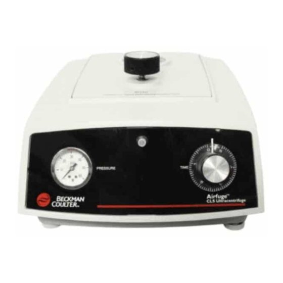
Description FUNCTIONAL DESCRIPTION The Beckman Coulter Airfuge® (see Figure 1-1) is a benchtop air-driven ultracentrifuge capable of accelerating rotors up to 110 000 rpm (revolutions per minute) in as little as 30 seconds. The instrument uses no vacuum or high-speed bearings; the rotor is supported and turned by streams of air. -
Page 16: Safety Features
Description SAFETY FEATURES The Airfuge ultracentrifuge has been designed and tested to operate safely indoors at altitudes up to 2 000 m (6 562 ft). The Airfuge is an exceptionally safe ultracentrifuge because the rotor is held in place by a pressure differential created during centrifugation. -
Page 17: Brake Tension Screw
Description Time Delay Knob Figure 1-2. Bottom Panel BRAKE TENSION SCREW The brake spring wire (see Figure 1-3) forces the brake pin up into the rotor bottom during braking. Occasional adjustment of the spring tension, using the BRAKE TENSION adjusting screw located on the back panel (see Figure 1-4), may be necessary. -
Page 18: Figure 1-3. Cross-Section View Of The Airfuge
Description Instrument Protective Window Door Stator Turbine Flutes Stator Driving Levitation Air Passage Air Passage Brake Pin Brake Spring Wire Electromagnet Figure 1-3. Cross-section View of the Airfuge Figure 1-4. Rear View... -
Page 19: Chamber Components
Levitation air operates automatically during deceleration. STATOR PAD The black stator pad (see Figure 1-5) rests on the channel of the stator and cushions the rotor during a run and when the rotor is at rest. Figure 1-5. Airfuge Components and Accessories... -
Page 20: Brake Pin
The filter element turns red when it is saturated and needs to be replaced. NAME RATING PLATE A name rating plate is affixed to the rear of the instrument. Always mention the serial number and model number when contacting Beckman Coulter regarding your Airfuge ultracentrifuge. -
Page 21: Specifications
Description SPECIFICATIONS Only values with tolerances or limits are guaranteed data. Values without tolerances are informative data, without guarantee. Speed range ......80 000 to 110 000 (±5 000) rpm Maximum relative centrifugal field*. -
Page 22: Available Rotors
Description AVAILABLE ROTORS Airfuge rotors are made of anodized aluminum and have turbine flutes on the bottom that provide the driving surface for the jets of air. Pressurized air impinges on the rotor bottom and lifts and turns the rotor. A white plastic bushing fitted in the rotor bottom is engaged by the brake pin during braking. -
Page 23: Space And Location Requirements
Installation SPACE AND LOCATION REQUIREMENTS WARNING Do not place the ultracentrifuge near areas containing flammable reagents or combus- tible fluids. Vapors from these materials could enter the ultracentrifuge air system and be ignited by the motor. Maintain a 30-cm (1-ft) clearance envelope around the ultracen- trifuge while it is running. -
Page 24: Electrical Requirements
To reduce the risk of electrical shock, this ultracentrifuge uses a three- wire electrical cord and plug to connect the ultracentrifuge to earth- ground. (Contact your local Beckman Coulter office for specific information regarding local requirements.) To preserve this safety feature: •... -
Page 25: Filter Installation
Escaping air can be heard if the filter is installed upside down. Filter Bottom From Air From Air Source Source Quick-disconnect hose from filter Quick-disconnect to Airfuge hose from filter Ultracentrifuge to Airfuge Barb Ultracentrifuge Fitting Arrow indicates direction of airflow... -
Page 26: Time-Delay Setting Check
120 seconds (or 3.5 on older instruments). LEVELING THE AIRFUGE The Airfuge must be leveled before use. 1. Place the supplied liquid level on the center of the stator. 2. Adjust the instrument front feet until the bubble of the level is... -
Page 27: Installing The Brake Pin And Stator Pad
Preinstallation Requirements INSTALLING THE BRAKE PIN AND STATOR PAD 1. Place the brake pin in the hole at the center of the stator (see Figure 2-2). Make sure that the slot in the pin bottom straddles the brake spring wire as shown in the figure. 2. -
Page 28: Trial Run
COLD ROOM INSTALLATION If rotor temperatures below room temperature are required, the Airfuge can be operated in a cold room. A typical cold room set-up is shown in Figure 2-3. In addition to the installation procedures above, the following variations are required. -
Page 29: Figure 2-3. Cold Room Set-Up
(330 kPa) Oil Removal Filter Regulator (Norgren Part No. 339620) COLD ROOM Water Removal Filter (Norgren F11-200A3T) 0.6 m (2 ft) or less 3 m (10 ft) of /8 in. ID finned Airfuge Ultracentrifuge copper tubing Figure 2-3. Cold Room Set-up... -
Page 31: Operation
Operation Refer to individual rotor manuals for detailed information on each rotor. WARNING Normal operation may involve the use of solu- tions and test samples that are pathogenic, toxic, or radioactive. Handle body fluids with care because they can transmit disease. No known test offers complete assurance that they are free of micro-organisms. -
Page 32: Starting The Run
➠ NOTE If you are using an Airfuge with the digital speed readout accessory installed, use a flat black marker to color half of the rotor lid or cap flat black. If the black surface is shiny, inaccu- rate speed readings will be displayed. -
Page 33: Figure 3-1. Worn And New Stator Pads
Operation Worn Stator Pads Stator Pad Figure 3-1. Worn and New Stator Pads 5. Place the rotor on the stator pad and shut the instrument door. 6. Set the TIME dial for the required run time. The dial indicates up to 5 hours of run time in 5-minute increments. -
Page 34: Ending The Run
Operation CAUTION If the rotor makes an unusual noise, turn the timer to zero. When the rotor stops, open the chamber door and remove the rotor. Check to make sure the rotor is loaded correctly. Correct the problem before restarting the run (see Table 4-1). -
Page 35: Troubleshooting
Perform the recommended corrective action in sequence, as listed. If you are unable to correct the problem, call Beckman Coulter Field Service. To help diagnose and correct the problem, provide as much information as possible: •... - Page 36 Troubleshooting Table 4-1. Troubleshooting. If the problem persists call Beckman Coulter Field Service. Problem Possible Cause Recommended Action Brake pin falls flat on stator Brake spring wire not centered Adjust the brake spring wire. surface Brake spring tension too low Adjust the brake spring tension.
- Page 37 Light burned out Replace the lamp. Circuit breaker tripped Reset the circuit breaker. Time delay faulty Call Beckman Coulter Field Service. Rotor crashes Stator pad worn Order Repair Kit 1. Missing rotor lid or cap Refer to the applicable rotor manual.
-
Page 39: Maintenance
This section contains care and maintenance procedures that should be performed regularly. For maintenance not covered in this manual, contact Beckman Coulter Field Service for assistance. Refer to the applicable rotor manual for instructions on the care of rotors and their accessories. -
Page 40: General Maintenance
Maintenance GENERAL MAINTENANCE Perform the following procedures regularly to ensure satisfactory performance and long service life of the ultracentrifuge. • At least once a week (depending on usage) inspect the interior of the rotor chamber for accumulations of foreign matter. Clean as required (see , below), as these accumulations can CLEANING... -
Page 41: Instrument Interior And Exterior
Maintenance INSTRUMENT INTERIOR AND EXTERIOR • Clean the instrument exterior surfaces by wiping with a damp cloth or washing with Beckman Solution 555™ (339555). Dilute the detergent 10 to 1 with water. Do not use acetone or other solvents. • To prevent accumulations of sample, dust, oil, dirt, or other foreign matter, regularly wipe the channel of the stator, the air jets, and the brake pin with isopropyl alcohol.* STATOR ASSEMBLY... -
Page 42: Lubrication
Replace the element when it turns red or when there is an additional drop of about 67 kPa (10 psig) in the air pressure that reaches the Airfuge. Instructions for replacing the element are in the Filter Element Kit (878587). -
Page 43: Figure 5-1. Prying Up The Stator
Maintenance Figure 5-1. Prying Up the Stator Figure 5-2. Lifting Out the Stator. Keep the stator level to prevent binding. Brake Pin Stator Screw Stator Screw Stator Brake Spring Wire Stator Slot Brake Spring Tension Adjust Figure 5-3. Stator O-Ring Positions Figure 5-4. -
Page 44: Brake Spring Wire Adjustment
Maintenance BRAKE SPRING WIRE ADJUSTMENT If the brake pin is flat on the stator surface, either the brake spring wire is out of position or the brake spring tension is too low. WARNING Disconnect the power cord and the air supply. 1. -
Page 45: Brake Spring Wire Tension Adjustment
Maintenance Figure 5-5. Location of the Brake Spring Wire from the Ultracentrifuge Bottom 5. Reinstall the stator and brake pin as described under CLEANING (Steps 8 through 11 of ), above. STATOR ASSEMBLY BRAKE SPRING WIRE TENSION ADJUSTMENT If the brake spring wire is centered but the brake pin drops flat on the stator, the brake spring wire tension requires adjustment. -
Page 46: Levitation Air Adjustment
3. Place a rotor on the stator pad. Be sure rotor caps or lids are properly installed. (The rotor does not need to be loaded.) 4. Close the Airfuge door and turn the pressure regulator knob on the door clockwise until the PRESSURE gauge indicates 30 psig (207 kPa). -
Page 47: Time-Delay Period Adjustment
Maintenance one-quarter turn further counterclockwise. The rotor will be wobbling and may be turning in either direction. Leave the LEVITATION AIR screw at this setting; this is the correct adjustment. 6. Turn the pressure regulator knob counterclockwise and open the door. -
Page 48: Decontamination
Maintenance 1. Close the Airfuge door and turn the instrument on its side. 2. Turn the time-delay knob counterclockwise to shorten the delay time, or clockwise to lengthen the delay time. 3. Reconnect the power cord and the air supply and perform a trial run to check the new setting. -
Page 49: Storage And Transportation
742-2345 in the United States, or by contacting your local Beckman Coulter office. Contact Beckman Coulter Sales (1-800-742-2345 in the United States; worldwide offices are listed on the back cover of this manual) for information about ordering parts and supplies. A partial list of supplies is given below for your convenience. - Page 51 Beckman Coulter will give rea- velop within one (1) year after delivery of the Airfuge Ultracen- sonable assistance to the Buyer in obtaining from the respective...
- Page 56 Beckman Coulter, Inc. • 250 S. Kraemer Blvd. • Brea, California 92821 Sales and Service: 1-800-742-2345 • Internet: www.beckmancoulter.com ©2009 Beckman Coulter, Inc. All rights reserved...
Need help?
Do you have a question about the Airfuge and is the answer not in the manual?
Questions and answers