
Summary of Contents for Comestero Suzohapp Multi PRO
- Page 1 Multi PRO Car wash starter system - Change machine Operating Manual Cod. Rev. 1.1 06 – 09 – 2017 DMMLP00001.1EN...
- Page 2 ...
- Page 3 GUIDE TO THE SYMBOLS IN THE MANUAL The following symbols are used in this manual in order to facilitate its understanding. Important information Read carefully before use Warning! ...
- Page 4 Antonie Van Leeuwenhoekstraat 9 3261 Oud-Beijerland LT - NETHERLANDS DECLARES that the products TYPE: Start system/change machine TRADEMARK: Comestero MODEL: Multi PRO Comply with the following European directives, including their latest changes, and with the relevant national laws implementing the directives in question:...
- Page 5 Multi PRO – Operating Manual SAFETY INFORMATION These machines are equipped with safety devices to prevent damage due to short circuits and fire. These devices must not be bypassed, removed or disabled for any reason. If the devices must be disabled to carry out any maintenance or servicing, operate on the appliances only when the power supply has been switched off.
- Page 6 Hazards during machine installation and setup Follow the machine installation instructions contained in this document to minimise hazards to people and property. Crushing hazards while handling the machine and putting it into place. The machine must be transported by a technician in possession of the qualifications required for load handling operations (forklift operators, etc...).
- Page 7 Multi PRO – Operating Manual Labels The machine is equipped with warning labels showing conventional hazard signs with symbols and/or written messages. The labels are located near the hazardous areas. GENERIC HAZARD ELECTROCUTION HAZARD GROUND ...
- Page 8 GENERAL WARRANTY CONDITIONS Please read the following carefully to understand the general warranty conditions for this product. ART.1 - Scope of application These general terms and conditions shall apply to all the goods and services provided by our company. Placing any orders shall imply the full and unconditional acceptance of these general terms and conditions of sale.
- Page 9 Multi PRO – Operating Manual with reference to all the electrical components and mechanical plastic moving parts subject to normal wear, which must be replaced during routine maintenance; when the products have been used in conjunction with or incorporated into equipment or materials whose specifications have not been approved in writing by the selling company ...
- Page 10 the Purchaser must carry out a complete technical verification of the quality and functionality of the product, within eight days. If not, the product shall be considered as having been accepted without reservations or objections by the Purchaser. ART. 6 - Retention of Title The supplied goods shall remain the property of our company until full payment of the agreed price has been made.
-
Page 11: Table Of Contents
Multi PRO – Operating Manual Table of contents 1 Introduction ............................ 14 2 System presentation and composition ..................15 General Features ..............................15 Installable devices ..............................16 3 Warnings ............................17 4 Handling and unpacking ......................18 Reception of the packaged product ........................18 Handling ................................... - Page 12 9.1.2 Function selection ............................47 9.1.3 Failure or malfunction of a device ......................47 9.1.4 Absence of a device ............................48 Purchasing a washing program ("Wash my car") ..................... 48 9.2.1 Payment ................................. 49 Purchasing tokens/coins ............................52 9.3.1 Payment .................................
- Page 13 Multi PRO – Operating Manual 14.2 Wall recessed version ............................106 14.3 Cabinet group – totem version (Cod. 1083-30-0101-A) ................108 14.4 Cabinet group – wall recessed version (Cod. 1083-30-0201-A) ..............110 14.5 Back door assembly – Totem version (Cod. 1083-30-0111-A) ..............111 14.6 Flange group –...
-
Page 14: Introduction
Introduction This manual and its annexes provide all the necessary information for a correct installation of the product and of all its parts, as well as for its correct use and maintenance. The information contained in this technical manual is subject to change without notice and does not imply any commitment by SUZOHAPP. -
Page 15: System Presentation And Composition
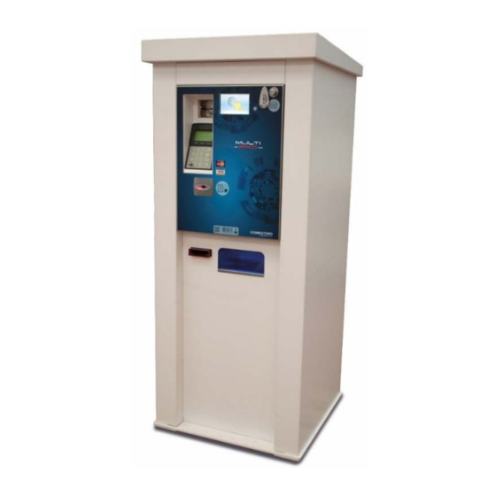
Multi PRO – Operating Manual System presentation and composition The Multi PRO machine is an innovative starter for the management of the services required by the most recent car wash lots. It offers advanced performances which can fully meet the most common needs in this field. -
Page 16: Installable Devices
Barcode reader Flexible installation: free-standing or recessed Structure resistant to external agents: water, dust and various types of atmospheric agents 2.2 Installable devices Multi PRO provides great configuration flexibility, allowing to install various combinations of devices to ensure that the system meets the purchaser’s needs. Installable devices include: ... -
Page 17: Warnings
Multi PRO – Operating Manual Warnings Carefully read this quick start guide before installation. Knowledge of the information and instructions contained in this manual is essential to properly use the product. Check upon receipt that the package and the product have not been damaged during transport. -
Page 18: Handling And Unpacking
Handling and unpacking 4.1 Reception of the packaged product Check upon receipt that the product has not been damaged during transport. Should you notice any damage, immediately notify the carrier. After transport the package must be intact, i.e. it must ... -
Page 19: Identification Of The Machine And Accessories
Multi PRO – Operating Manual For unpacking, we recommend that you follow the instructions printed on the box. Both the carton package and the pallet comply with the recycling and disposal standards (follow current local regulations). 4.4 Identification of the machine and accessories Figure 1 shows the location of the identification label, specifying the main operating and identification characteristics of the machine. - Page 20 Free-standing version Figure 2 - Cabinet outer side, free-standing version Figure 3 - Cabinet inner side, free-standing version ...
- Page 21 Multi PRO – Operating Manual Recessed version Figure 4 - Cabinet outer side, recessed version Figure 5 - Cabinet inner side, recessed version The identification label is installed on the machine and must be clearly readable.
-
Page 22: Installation
nstallation 5.1 Recessed installation The drawing below shows the dimensions of Multi PRO in its recessed version to facilitate its placement and installation. Figure 6 ... - Page 23 Multi PRO – Operating Manual For recessed installation you must prepare, in the wall where you intend to install the machine, a recess with the dimensions shown in the diagram below The access room behind the machine, in addition, must be large enough to allow the back door of the equipment to be opened.
-
Page 24: Installation In Free-Standing Cabinet
5.2 Installation in free-standing cabinet As mentioned above, should recessed installation be impossible, or should you wish to install it in the car wash lot for better protection, Multi PRO can be installed in a special cabinet. The drawing below shows the dimensions of Multi PRO in its free-standing version to facilitate its placement and installation (Figure 8). - Page 25 Multi PRO – Operating Manual Diagram A in Figure 9 below shows the cabinet base configuration and the dimensions for proper installation by means of 14 mm diameter pins. Diagram B shows the configuration and overall dimensions of the cabinet cover. ...
-
Page 26: Mechanical Configuration
Mechanical configuration 6.1 Main variants Multi PRO offers several configuration options depending on customer needs. As mentioned above, Multi PRO is sold and supplied to customers in two main variants: free-standing and recessed. FREE-STANDING: Figure 10 RECESSED: Figure 11 ... -
Page 27: Device Options
Multi PRO – Operating Manual Design variants differ internally by the combination and location of the devices installed on them, and externally by the location of the payment devices. N.B. The operation and the on-board configuration procedures remain the same for both Multi versions. ... -
Page 28: Hopper - Free-Standing Version
6.2.2 Hopper - free-standing version Figure 13 In the free-standing cabinet version, hoppers are located as shown in Figure 13 above. You have the option to install no hopper (A), a single hopper (B), two hoppers (C) or three hoppers (D). -
Page 29: Payment Systems - Pos
Multi PRO – Operating Manual 6.2.4 Payment systems - POS The POS may or may not be available, depending on the type of Multi PRO you own, for both free-standing and recessed configuration (to verify whether it is available in your country, please contact your reference sales account). -
Page 30: Dispensers - Free-Standing And Recessed Version
6.2.5 Dispensers – free-standing and recessed version In both free-standing and recessed versions, you can install a maximum of two dispensers for the on-board sale of keys or cards. The following pictures show their location. Free-standing version Figure 16 ... -
Page 31: Door Opening
Multi PRO – Operating Manual 6.2.6 Door opening In order to meet the different installation needs, Multi PRO can be supplied with two door opening types: hinged on the left or on the right. Figure 18 ... -
Page 32: Connections
Connections 7.1 Connection to power supply All the electrical connections of the machine have been installed, except for the power supply. Before connecting the machine to the mains, make sure that the main switch, located at the bottom left on its inner wall, is turned to "0"... -
Page 33: Connection To The Maxibio Boards
Multi PRO – Operating Manual 7.2 Connection to the MaxiBio boards Before connecting the MaxiBio board to Multi PRO machine, make sure that the main switch of the machine, which is located inside the unit on the left wall, is turned to "0" (Figure 19) and that the machine is completely OFF. - Page 34 CONNECTION TO THE MAXIBIO BOARD Figure 21 The diagram below shows the MaxiBio board. RED WHITE BLACK GREEN WIRE WIRE WIRE WIRE ...
- Page 35 Multi PRO – Operating Manual This board has: 8 output terminals (Cn2 to Cn16), 8 input terminals (a to h) and one input for the 24 VDC ± 20% low voltage power supply. Connect the MaxiBio board to the equipment as shown. Connect the input and output signals to the MaxiBio board referring to the diagrams below and in the following page.
- Page 36 Figure 24 red wire Multi PRO connection black wire 24 Vdc ±20% white wire green wire INPUT Alarm Non-configurable inputs Plant busy (STANDARD version) Vehicle in position f Inputs with configurable Configurable inputs g functions h ...
- Page 37 Multi PRO – Operating Manual MaxiBio Fig. 25 red wire Multi PRO connection 24 Vdc ± 20% black wire white wire SET AS green Wire ADDRESS 1 INPUTS Alarm Non-configurable inputs Plant busy (STANDARD version) Extra height Vehicle in position General purpose input General purpose input Configurable inputs...
-
Page 38: Connection To The Ethernet Network
Even the MaxiBio board is not included in the packaging and must be requested from COMESTERO to ensure that the connected system is properly driven. To connect the MaxiBio board to the gantry car wash, use cables that can withstand a 230 Vac voltage. These cables must be supplied by the installer. - Page 39 Multi PRO – Operating Manual Figure 22 Please note that this structure is only valid for the machine that includes the POS. For the version without the POS, the Ethernet port is placed into the motherboard. To insert the connector into the port, please follow the procedure below: ...
-
Page 40: User Interface
User interface The user interface screens include some recurring elements with which the user will have to interact by touching the display. 8.1 Buttons A screen may include one or more buttons; touching them will immediately trigger an action. For example, in the screen shown in Figure 23 below, touching the "Wash my car"... - Page 41 Multi PRO – Operating Manual When inside a menu listing the available options over multiple pages, or while following a wizard that requires a sequence of choices, the screen will display the "> Next" button, allowing to switch to the next page, like in the screens shown in Figure 25 and Figure 26 below. ...
-
Page 42: Checkbox
8.2 Checkbox A checkbox is a control box. It represents a Yes/No condition, which is displayed as a checked or unchecked box. Touching a checkbox will allow to enable or disable a given functions, like in the screen shown in Figure 27 below. -
Page 43: Text And Value Input Fields
Multi PRO – Operating Manual 8.4 Text and value input fields Whenever the user must set a value or input a text, the screen will display an input field. For example, the screen shown in Figure 29 below includes fields that allow to input a name and an email address. - Page 44 The screen shown in Figure 31 below, instead, includes fields that allow to set a value. Figure 31 For example, touching the "Price” field will display the screen shown in Figure 32 below, which allows to input the desired value by touching the different number keys. ...
-
Page 45: Information Text
Multi PRO – Operating Manual 8.5 Information text If the software is designed to show simple text messages that the user can only read without interacting with them, the screen will display some information text, like in the screen shown in Figure 33 below. -
Page 46: Using The Equipment
Using the equipment 9.1 Introduction All the purchases, or the management and configuration of the Multi PRO machine, can be carried out using a 5” touch screen. It allows the customer to choose and activate the desired service among the ones proposed by the machine, like the desired washing program, or the purchase of cards or keys, etc. -
Page 47: Function Selection
Multi PRO – Operating Manual 9.1.2 Function selection Once the user touches the screen, the machine presents him with a range of options and services that are available for purchase; the user can choose among: "Wash my car", "Buy tokens/coins"... -
Page 48: Absence Of A Device
9.1.4 Absence of a device In the event one or more of the machine internal devices were not installed, the function selection screen will not display the option associated with the absent device, looking very much like the one shown in Figure 37 below. ... -
Page 49: Payment
Multi PRO – Operating Manual Check that the vehicle is properly in place, then touch the "Yes!" button to proceed. The system will display the screen shown in Figure 39 below, allowing to choose the washing program. Figure 39 ... - Page 50 inserted the cash (coins, banknotes) or a cashless device (like a key, a tag or a card). In case of cash payment, Multi PRO will display both the total price and any sums still due once the banknotes or coins have been inserted. ...
- Page 51 Multi PRO – Operating Manual Figure 43 If the printer is installed, once the user has inserted the money, he will be prompted to specify whether he wants the receipt to be printed, as shown in Figure 44 below. Touch the "Yes!" button to print the receipt;...
-
Page 52: Purchasing Tokens/Coins
The selected program will then be started and the system will display the screen shown in Figure 45 below. Multi PRO will keep the gantry car wash busy until the washing cycle has been completed. Figure 45 ... -
Page 53: Payment
Multi PRO – Operating Manual Figure 47 Touching one of the buttons on the right side of the screen will allow to proceed with the payment. 9.3.1 Payment See paragraph 9.2.1 9.4 Purchasing a card or a key Touching the "Buy card/key"... -
Page 54: Payment
9.4.1 Payment See paragraph 9.2.1 9.5 Adding credit to a card or a key Touching the "Load my card/key" button reproduced on the right in the screen shown in Figure 35 will display the screen shown in Figure 49 below. ... -
Page 55: Payment
Multi PRO – Operating Manual 9.5.1 Payment See paragraph 9.2.1 Once the payment is completed, wait until the sum is added to the card (or key) inserted in the cashless reader Once the operation is completed remove the card (or key) from the cashless reader of the machine to finish the recharge procedure, as also stated by the message displayed on the screen shown in Figure 51 below. -
Page 56: Onboard Programming
Onboard programming 10.1 Introduction All Multi PRO menus (configuration, accounting, etc…) are protected by a specific password according to the type of authorisations granted to the user (an exclusive password for the accounting menu, one for the configuration menu, one for the other system menu functions, etc…). -
Page 57: Shutdown
Multi PRO – Operating Manual Once the user has entered the password the system will display the machine system menu, as shown in Figure 53 below. Touch one of the buttons included in this menu to access the relevant functions. ... -
Page 58: Components Setup
This screen (shown in Figure 54 below) grants access to the various menus allowing to modify the settings and the main properties of Multi PRO. Figure 54 10.4.1 Components setup Touching the "Components Setup" button reproduced on the right will display a screen similar to the one shown in Figure 55 below. - Page 59 Multi PRO – Operating Manual 10.4.1.1 Coin acceptor RM5 HD The coins or tokens accepted by the coin mechanism are displayed according to the programming channel. You can enable or disable them without intervening on the coin mechanism. You can generally set 2 different tokens, as shown for example in Figure 56 below. To have the device recognise a new token, touch one of the two buttons: and insert at least 15 tokens into the coin mechanism.
- Page 60 10.4.1.2 Currenza C change giver All the coins the change giver can accept are displayed according to the programming channel. You can enable or disable the acceptance channel without directly intervening on the change giver, by touching the corresponding checkbox. ...
- Page 61 Multi PRO – Operating Manual Touching the "Next >" button will display the screen shown in Figure 59 below. The screen includes a "Test" button, used to check that the change giver is working properly (each time you click the button the device will dispense a coin or a token). The "Empty" button will allow to completely empty the change giver.
- Page 62 To fill the change giver, press the "Refill" button in the screen shown in Figure 59. The system will display the screen shown in Figure 63 below. Figure 61 Please note that the value displayed in the stock management menu or during the emptying operations doesn’t include the last 3 coins in each tube (security stock) to guarantee the maximum reliability of the device.
- Page 63 Multi PRO – Operating Manual Touching the "Next >" button will display the screen shown in Figure 63 below. The screen includes a "Test" button used to check that the banknote validator is working properly. Figure 63 ...
- Page 64 Touch the "NEXT >" button to confirm and switch to the next screen, shown in Figure 65 below, which allows to setup the recycler. You can set which banknote shall be sent into the recycler by touching the "Payout value" field and entering the value into it.
- Page 65 Multi PRO – Operating Manual 10.4.1.6 Evolution hopper The Evolution hopper can deliver a single coin or token denomination selected by the user. A specific screen in the "System Menu" allows to set the coin (Euro denomination or token) the single hopper will have to deliver.
- Page 66 To define the number of coins/tokens inserted manually when filling the hopper, press the "Refill" button in the screen shown in Figure 67. The system will display the screen shown in Figure 69 below. Figure 69 Pressing the "Add" button will allow to set the number of tokens/coins that were inserted. 10.4.1.7 Card or key dispenser You can install two card or key dispensers in the machine.
- Page 67 Multi PRO – Operating Manual Should you choose to empty the dispenser, touch the "Empty" button. The machine will display the screen shown in Figure 71 below. Touch "Confirm!" to empty the dispenser; touch "X Cancel" to return to the previous screen without emptying the dispenser. ...
- Page 68 10.4.1.8 Printer Should the Multi PRO machine detect that the paper stock is about to run out during normal printer operation (even thanks to the sensor installed on it), it can send a warning e-mail to the e-mail address specified during the configuration, reminding the recipient that the paper needs to be replaced.
- Page 69 Multi PRO – Operating Manual 10.4.1.9 MaxiBIO board Maxibio is the input/output board allowing to interface Multi PRO with the car wash system. The flexibility in configuring the inputs and outputs to be used, their communication mode and their default level allows Multi PRO to assure fully compatibility with all the gantry car washes on the market.
- Page 70 Touch "Next >" to confirm and access the next screen, allowing to define the MaxiBio board inputs. If you installed a vehicle position sensor, you will have to check the "Car position" option, as shown in Figure 77 below. The green LED in front of each input indicates its status (green if the input is active).
- Page 71 Multi PRO – Operating Manual Figure 79 The "Test" buttons allow to simulate the activation of a program and indicate the corresponding output(s) (in binary mode) in the terminal strip connection diagram, making testing the wiring easier than ever. The eighth output of the MaxiBio terminal strip allows to drive a coin vacuum system.
-
Page 72: Machine Functions
10.4.2 Machine Functions Touching the "Machine Setup" button reproduced on the right in the screen shown in Figure 54 will display the relevant menu home page. This page (shown in Figure 81 below) allows to access the programming functions for the operations the user can manage through the touch screen. - Page 73 Multi PRO – Operating Manual Touching one of the buttons on the right side of the screen will display a screen similar to the one shown in Figure 83 below, allowing to associate the button with a washing program, including the relevant settings.
- Page 74 10.4.2.1.1 Correct car position Touching the "> Next" button in the screen shown in Figure 82 will display the screen shown in Figure 84 below. Figure 84 If the control of the proper vehicle position before the washing cycle begins is going to be performed by a presence detector connected to Multi PRO (see paragraph 10.4.1.9.1), this screen is not displayed.
- Page 75 Multi PRO – Operating Manual You can make each operation available/unavailable to the user irrespective of the others, by simply touching the corresponding checkbox (tick displayed = operation available) 10.4.2.2.1 Tokens Touching the "Tokens n.nn €" button in the screen shown in Figure 85will display the screen shown in Figure 86 below, allowing to set the amount of tokens dispensed for the amount of money inserted by the user.
- Page 76 10.4.2.2.2 Coins Touching the "Coins n.nn €" button in the screen shown in Figure 85will display the screen shown in Figure 88 below, allowing to set the amount of coins dispensed for the money inserted by the user. ...
- Page 77 Multi PRO – Operating Manual 10.4.2.2.3 Mix Touching the "Mix" button in the screen shown in Figure 85will display the screen shown in Figure 90 below, allowing to set the amount of tokens/coins dispensed for the amount of money inserted by the user. ...
- Page 78 Touching the "> Next" button will display a screen similar to the one shown in Figure 92 below, allowing to associate with the button one or more token/coin mixes dispensed in exchange for the inserted amount. Figure 92 ...
- Page 79 Multi PRO – Operating Manual 10.4.2.2.4 Token purchase with card/key Touching the "> Next" button on the screen shown in Figure 85 will display the screen shown inFigure 94 below (only if the machine is equipped with at least one token-dispensing hopper and a cashless payment system).
- Page 80 Touching one of the buttons on the right side of the screen will display a screen similar to the one shown in Figure 96 below, allowing to associate with the button an amount of money the user may choose to insert, and a possible bonus that will be associated. ...
- Page 81 Multi PRO – Operating Manual Figure 97 You can make each operation available/unavailable to the user irrespective of the others, by simply touching the corresponding checkbox (tick displayed = operation available) Touching the "Card n.nn €" button in the screen shown in Figure 102 will display the screen shown in Figure 98 below, allowing to set the amount of money the user may insert.
-
Page 82: Various
Figure 99 Touch the "Enable button" checkbox to enable/disable the corresponding button (a disabled button will keep the stored settings but will not be displayed in the screen shown in Figure 98). Enter in the "Price" field the amount of money the user may choose to insert (the software will calculate a corresponding amount of cards, based on the unit value of the card). - Page 83 Multi PRO – Operating Manual Figure 101 There are four access levels; for each of them you can set various authorisations, in addition to the four-digit code. By touching the corresponding check box you can enable each level to perform setup (first column) and accounting (second column) operations;...
- Page 84 To remove a recipient just touch the trash bin button. You will not be prompted to give any further confirmation. Touching the "Email Account Setup" button will display the screen shown in Figure 103 below, allowing to set the connection parameters. ...
- Page 85 Multi PRO – Operating Manual 10.4.3.3 Language Touching the "Language" button reproduced on the right in the screen shown in Figure 100 will display the screen (shown in Figure 104 below) allowing to set the display languages. Figure 104 Touching the "Change"...
- Page 86 10.4.3.4 Closing hours Touching the "Closing hours" button reproduced on the right in the screen shown in Figure 100 will display the screen (shown in Figure 106 below) allowing to set the time slot during which Multi PRO will be in operation. ...
-
Page 87: Advanced
Multi PRO – Operating Manual 10.4.4 Advanced Touching the "Advanced" button reproduced on the right in the screen shown in Figure 54 will display the relevant menu home page. This screen (shown in Figure 108 below) allows to program some advanced system functions. ... - Page 88 10.4.4.1 System Info Touching the "System info" button reproduced on the right in the screen shown in Figure 108 will display the screen (shown in Figure 110 below) allowing to display the serial number, the IP address and the firmware version of the ...
- Page 89 Multi PRO – Operating Manual 10.4.4.2.1 Configuration Touching the "Configuration" button reproduced on the right in the screen shown in Figure 111 will display the screen (shown in Figure 112 below) allowing to export the configuration data to an external device through the USB port.
- Page 90 10.4.4.3 System Update Touching the "System Update" button reproduced on the right in the screen shown in Figure 108 will display the relevant menu home page. This screen (shown in Figure 113 below) allows to access the data import and system update functions.
- Page 91 Multi PRO – Operating Manual 10.4.4.4 Set Date/Time Touching the "Set Date/Time" button reproduced on the right in the screen shown in Figure 109 will display the screen (shown in Figure 114 below) allowing to intuitively set the system time and date by touching the different buttons. ...
-
Page 92: Saving Changes
10.4.5 Saving changes After modifying one or more settings, if you touch the "Close" button in the screen shown in Figure 53 the system will display the screen shown Figure 116 below. Figure 116 If you touch the "X No and proceed" button the setup changes will not be saved and the display will switch back to the screen shown in Figure 34. -
Page 93: Pos Operation
Multi PRO – Operating Manual 10.5 Pos Operation Touching the "Pos Operation" button reproduced on the right in the screen shown in Figure 53 will display the POS menu home page. This screen (shown in Figure 117 below) allows to access the various POS operation management functions. -
Page 94: Accounting
10.6 Accounting Touching the "Accounting" button reproduced on the right in the screen shown in Figure 53 will display the screen (shown in Figure 117 below) allowing to analyse the whole commercial activity carried out on the machine during a ... - Page 95 Multi PRO – Operating Manual Touching the "> Next" button will display the second page of the report, shown in Figure 120 below. Figure 120 Touch the "Email" button on the screen shown in Figure 118 to send the data to the recipients enabled to receive machine accounting communications (see paragraph 10.4.3.2).
-
Page 96: Manual Mode
By touching one of the buttons corresponding to a container, you will be able to choose the number of tokens/coins/cards to be inserted and to confirm; the system will then display the screen shown in Figure 122 below, prompting you to start inserting the items. ... -
Page 97: Manual Wash
Multi PRO – Operating Manual 10.7.1 Manual Wash Touching the "Maintenance" button reproduced on the right in the screen shown in Figure 123 will display the screen (shown in Figure 124 below) allowing to enable/disable the manual washing mode. ... -
Page 98: Free Tokens
10.7.2 Free tokens Touching the "Free tokens" button reproduced on the right in the screen shown in Figure 123 will display the screen (shown in Figure 124 below). Figure 126 Set the token type and the number of pieces to be dispensed, then touch the "OK" button to confirm. - Page 99 Multi PRO – Operating Manual The system will display the screen shown in Figure 128 below, informing you that printing is under way. Figure 128 ...
-
Page 100: Care And Maintenance
Care and maintenance All maintenance inside the machine must be carried out when the power supply has been switched OFF. You should carefully follow the warnings contained herein, to ensure that the machine is always in the best operating conditions, preventing dangerous situations or situations which would render the warranty null and void. -
Page 101: Diagnostics And Technical Support
Multi PRO – Operating Manual Diagnostics and technical support This section lists the main faults that may be noticed during operations and the corresponding possible solution, in order to minimise or completely eliminate any need for machine shut-down. ... -
Page 102: Technical Data
Technical data Free-standing Recessed version version Dimensions (BxHxP) [mm]: 630 x 1,448.15 x 590 503 x 770 x 518 Weight [Kg]: Supply voltage [Vac]: Power consumption [VA]: Operating temperature [°C]: -15 ÷ +50 -15 ÷ +50 Non condensed humidity [%]: 10 ÷... - Page 103 Multi PRO – Operating Manual Optional peripheral devices and accessories Cashless system: Eurokey Next Tropicalized electronic coin mechanism: Comestero RM5 HD Change giver: SUZOHAPP Currenza C Banknote validator: Innovative Technology NV9 Banknote recycler: Innovative Technology NV11 Hopper: SUZOHAPP Evolution Hopper...
-
Page 104: Spare Parts
Spare Parts Perfectly identical to the parts to be replaced, our spare parts are in compliance with manufacturing specifications, and they guarantee with time optimum performance and reliability, satisfying all industry regulations for which they are designed. For any further information about this spare parts list, please visit our website suzohapp.com ... -
Page 105: Totem Version
Multi PRO – Operating Manual 14.1 Totem version Figure 129 PART NUMBER DESCRIPTION 1083-30-0101-A Cabinet group – totem version 1083-30-0402-A Group pred. Hopper – totem version 1083-30-0213-A Batteries group 1083-30-0598-A Coin box group 1083-30-0211-A Collecting coins box group 1083-30-0399-A Assembly group Touch + display 1083-30-0214-A... -
Page 106: Wall Recessed Version
14.2 Wall recessed version Figure 130 PART NUMBER DESCRIPTION 1083-30-0401-A Group pred. Hopper – recessed version 1083-30-0201-A Cabinet group 1083-30-0598-A Coin box group 1083-30-039-A Assembly group Touch + display 1083-30-0801-A Box (keys) dispenser group 1083-30-0802-A Mifare cards dispenser group... - Page 107 Multi PRO – Operating Manual 1083-30-1201-A Printer group 1083-30-0299-A Rear door group – wall recessed group 1083-30-0601-A NV9 banknote reader group ...
-
Page 108: Cabinet Group - Totem Version (Cod. 1083-30-0101-A)
14.3 Cabinet group – totem version (Cod. 1083-30-0101-A) Figure 131 ... - Page 109 Multi PRO – Operating Manual PART NUMBER DESCRIPTION 1083-30-0108-A Hinge group – totem version 1083-30-0111-A Back door assembly – totem version Backside panel Base plate Cover panel Lock Frontal panel Hopper supporting plate Intermedium supporting plate Left corner supporting base Left panel Right corner supporting base Right panel...
-
Page 110: Cabinet Group - Wall Recessed Version (Cod. 1083-30-0201-A)
14.4 Cabinet group – wall recessed version (Cod. 1083-30-0201-A) Figure 132 PART NUMBER DESCRIPTION 1083-30-0213-A Batteries group 1083-30-0211-A Collecting coins box group 1083-30-0214-A Heating group 1083-30-0212-A Power supply group - 230V 1083-30-0210-A Flange group – wall recessed version Hopper sliding rail 30309000000005A Cooling fan EBM-PAPST 8414NH... -
Page 111: Back Door Assembly - Totem Version (Cod. 1083-30-0111-A)
Multi PRO – Operating Manual 14.5 Back door assembly – Totem version (Cod. 1083-30-0111-A) Figure 133 PART NUMBER DESCRIPTION Rear door Lock cam M2P 1083-20-0114-A Lock Button handle - alloy Mobile lock ... -
Page 112: Flange Group - Wall Recessed Version (Cod. 1083-30-0210-A)
14.6 Flange group – wall recessed version (Cod. 1083-30-0210-A) Figure 134 PART DESCRIPTION NUMBER Lower zinc-coated and painted counterflange Upper zinc-coated and painted counterflange ... -
Page 113: Door Group - Wall Recessed Version (Cod. 1083-30-0299-A)
Multi PRO – Operating Manual 14.7 Door group – wall recessed version (Cod. 1083-30-0299-A) Figure 135 PART NUMBER DESCRIPTION Blocking cam Handle Backside door Rod latch SMINI6KD/2 Encoded mini 6 lock ... -
Page 114: Frontal Assembly Panel Group
14.8 Frontal assembly panel group Figure 136 PART NUMBER DESCRIPTION N40IB 40x28 8ohm 2W loudspeaker POS IUC 150 contactless cover bracket Frontal panel (POS hole) 1083-30-0711-A EuroKey Next group 1083-30-1101-A Barcode reader group 2514-CARWASH-A MCB4 CPU, MCB4 EXT, SD-card group Motion sensor plate 1083-30-0901-A Xenteo POS group... -
Page 115: Eurokey Next Option (Cod. 1083-30-0711-A)
Multi PRO – Operating Manual 14.9 EuroKey Next option (Cod. 1083-30-0711-A) Figure 137 PART NUMBER DESCRIPTION MCF Full flange RFT-NEXT Eurokey Next MCF antenna seal ... -
Page 116: Rm5 Hd Option (Cod. 1083-30-0501-A)
14.10 RM5 HD option (Cod. 1083-30-0501-A) Figure 138 PART NUMBER DESCRIPTION Coins acceptance channel / hopper B1000 C adapter Coins acceptance channel GEH251000660* RM5 HD coin validator – V version - tropicalised Button group (coin reject) Reject lever Reject lever plate ... -
Page 117: Currenza C 2 Option (Cod. 1083-30-0502-A)
Multi PRO – Operating Manual 14.11 Currenza C option (Cod. 1083-30-0502-A) Figure 139 PART NUMBER DESCRIPTION C2-X15474* coin recyler Coins acceptance channel / hopper Coins acceptance channel Button group (coin reject) Reject lever Reject lever plate ... -
Page 118: Cpu Group (Cod. 2514-Carwash-A)
14.12 CPU Group (Cod. 2514-CARWASH-A) Figure 140 PART NUMBER DESCRIPTION CPU carter CPU support MCB4_CPU board + Programmed SD-Card Micro SDHC 8G Classe 10 2514-CARWASH-A MCB4_EXT ass. ... -
Page 119: Hopper Group - Wall Recessed Version (Cod. 1083-30-0401-A)
Multi PRO – Operating Manual 14.13 Hopper group – Wall recessed version (Cod. 1083-30-0401-A) Figure 141 PART NUMBER DESCRIPTION 1083-20-0008-A 3 hoppers sliding trolley support Metallic support Cable carrier chain Couple of sliding guides on balls with release device Mod. -
Page 120: Hopper Group - Totem Version (Cod. 1083-30-0402-A)
14.14 Hopper group – Totem version (Cod. 1083-30-0402-A) Figure 142 PART NUMBER DESCRIPTION 3 hoppers sliding trolley support Metallic support Cable carrier chain Couple of sliding guides on balls with release device Mod. 4003 L = 300mm Closing plate Slide for Evolution hopper with connector on the adjacent position... -
Page 121: Batteries Group (Cod. 1083-30-0213-A)
Multi PRO – Operating Manual 14.15 Batteries group (Cod. 1083-30-0213-A) Figure 143 PART NUMBER DESCRIPTION 30206000000007A YUASA 12V 2,1Ah battery Batteries bracket 14.16 Coin box group (Cod. 1083-30-0598-A) Figure 144 PART NUMBER DESCRIPTION 1083-20-0011-A Coin box Tubular lock 17 mm KD ... -
Page 122: Barcode Scanner Option (Cod. 1083-30-1101-A)
14.17 Barcode scanner option (Cod. 1083-30-1101-A) Figure 145 PART NUMBER DESCRIPTION Fixed support (code reader) 30526000000189A_LAV Motorola SE-3307 barcode scanner Movable support (code reader) Protection glass (code reader) 14.18 Collecting coins box group (Cod. 1083-30-0211-A) Figure 146 ... -
Page 123: Heating Group (Cod. 1083-30-0214-A)
Multi PRO – Operating Manual 14.19 Heating group (Cod. 1083-30-0214-A) Figure 147 PART NUMBER DESCRIPTION Heating support Cooling fan/ballast - DBK Typhoon 40 225-275W Thermostat ... -
Page 124: Box Dispenser Option (Cod. 1083-30-0801-A)
14.20 Box dispenser option (Cod. 1083-30-0801-A) Figure 148 ... - Page 125 Multi PRO – Operating Manual PART NUMBER DESCRIPTION Cable assembly (box dispenser) Sliding support (box dispenser) C lawn tractor 20-13820-B Boxes storage Box dispenser weight Closing plate CCTINT2 board – programmed and tested ...
-
Page 126: Mifare Cards Dispenser Option (Cod. 1083-30-0802-A)
14.21 Mifare cards dispenser option (Cod. 1083-30-0802-A) Figure 149 PART NUMBER DESCRIPTION Dispenser card supporting plate 30052300000188A Mifare Card dispenser - CD200 24V 2.0s CCTINT4 board – programmed and tested... -
Page 127: Power Supply Group - 230Vac
Multi PRO – Operating Manual 14.22 Power supply group - 230Vac (Cod. 1083-30-0212-A) Figure 150 PART NUMBER DESCRIPTION 20514000000162A Power supply - 230Vac in - 24Vdc out 6A Power supply carter - 230V Main filter with two fuses 20514000000166A Ass. -
Page 128: Printer Option (Cod. 1083-30-1201-A)
14.23 Printer option (Cod. 1083-30-1201-A) Figure 151 PART NUMBER DESCRIPTION Bracket End paper sensor - TG2460H Paper roll - 60x80 TG2460 PCTG2460H TG 2460 H printer... -
Page 129: Nv9 Banknote Reader Option (Cod. Brak Grupy)
Multi PRO – Operating Manual 14.24 NV9 banknote reader option (Cod. Brak grupy) Figure 152 PART NUMBER DESCRIPTION LS/NV9/V-CCT-PA190* NV9 USB banknote reader – vertical version *EUR version. Please contact us for other currencies. ... -
Page 130: Xenteo Pos Mechanical Option
14.25 Xenteo POS mechanical option (Cod. 1083-30-0901-A) Figure 153 PART NUMBER DESCRIPTION XENTEO card reader CBX-TPA/FR XENTEO pinpad XENTEO mounting support XENTEO support... -
Page 131: Ingenico Pos Mechanical Option
Multi PRO – Operating Manual 14.26 Ingenico POS mechanical option IUN250+IUC250 (Cod. 1083-30-0902-A) Figure 154 PART NUMBER DESCRIPTION Ingenico IUR250 card reader 30306000000023A Ingenico IUP250 pinpad 30306000000025A Ingenico IUC150 contactless reader Ingenico IUN250 support ... -
Page 132: Nayax Pos Mechanical Option
14.27 Nayax POS mechanical option (cod. 1083-30-0903-A) Figure 155 PART NUMBER DESCRIPTION Cross recessed pan head screw NAYAX POS yellow kit - CPU NAYAX POS yellow kit – card reader ... -
Page 133: Appendices
Multi PRO – Operating Manual Appendices 15.1 Wiring diagram Figure 156 ... -
Page 134: Decommissioning And Disposal
15.2 Decommissioning and disposal At the end of its life the product must be decommissioned and sent to a disposal centre. Remove the machine from its installation place, empty it of all coins and remove the power cable. Contact SUZOHAPP for the collection of the decommissioned machine Call the following telephone number: +39 02.95781111. - Page 135 Multi PRO – Operating Manual The following sanctions will be applied in case of unlawful waste disposal: In the case provided for by article 6, paragraph 1, letter b), a dealer that does not accept the return of a used electrical or electronic equipment for free will incur a monetary sanction of Euro 150 to Euro 400 for each device that is not accepted or is accepted for a fee.
- Page 136 A manufacturer that does not communicate the information provided for by article 13, paragraph 8 to the national register of the subjects obliged to dispose of WEEE within the terms set out by article 13, paragraphs 4 3 5 can incur penalties. ...
- Page 137 EMA Headquarters NCS Headquarters APA Headquarters Antonie van Leeuwenhoekstraat 9 1743 Linneman Rd 44-48 Rocco Drive, Scoresby 3261LT Oud-Bijerland The Netherlands Mount Prospect IL 60056 USA Victoria Australia 3179 P +31 (0) 186 643333...
Need help?
Do you have a question about the Suzohapp Multi PRO and is the answer not in the manual?
Questions and answers