Table of Contents
Advertisement
V
A
V
Z
o
n
e
I
I
C
o
n
t
r
o
l
l
e
r
s
V
A
V
Z
o
n
e
I
I
C
o
n
t
r
o
l
l
e
r
s
I
n
s
t
a
l
l
a
t
i
o
n
a
n
d
S
t
a
r
t
-
u
p
G
u
i
d
e
I
n
s
t
a
l
l
a
t
i
o
n
a
n
d
S
t
a
r
t
-
u
p
G
u
i
d
e
CARRIER CORPORATION ©2019
A member of the United Technologies Corporation family · Stock symbol UTX · Catalog No. 11-808-602-01 · 8/30/2019
Advertisement
Table of Contents

Related Manuals for Carrier VAV Zone II


Summary of Contents for Carrier VAV Zone II
- Page 1 CARRIER CORPORATION ©2019 A member of the United Technologies Corporation family · Stock symbol UTX · Catalog No. 11-808-602-01 · 8/30/2019...
- Page 2 Verify that you have the most current version of this document from www.hvacpartners.com or your local Carrier office. Important changes are listed in Document revision history at the end of this document. CARRIER CORPORATION ©2019. All rights reserved throughout the world. i-Vu is a registered trademark of Carrier...
-
Page 3: Table Of Contents
To wire ZS sensors to the controller ....................17 To wire the Wireless Adapter for wireless sensors ................18 To wire an Equipment Touch to the VAV Zone II ................20 To wire the TruVu™ ET Display ......................21 Wiring sensors to the VAV Zone II's inputs ....................22 To wire the T55 sensor to the controller .................... - Page 4 I/O Points ................................95 Appendix B: VAV terminal modes ..........................98 Appendix C: ZS Sensor display for VAV Zone II ....................100 Appendix D: BACnet points list for the VAV Zone II Fan Terminal ..............101 Document revision history ............................. 104...
-
Page 5: Introduction
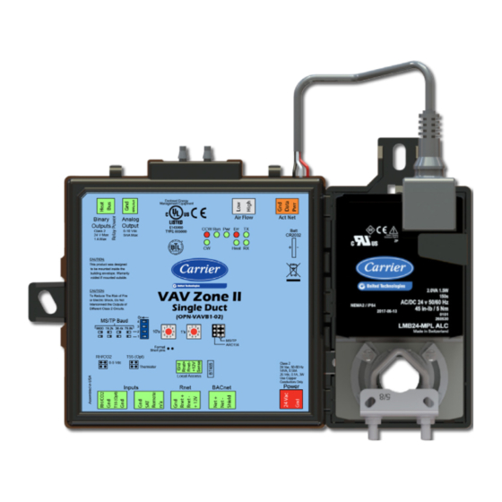
300 feet. Although a VAV Zone II can be included in a VVT system, this manual focuses mainly on its usage in VAV applications.The VAV Zone II has a detachable actuator and maintains zone temperature by operating the terminal fan and regulating the flow of conditioned air into the space. - Page 6 Introduction VAV Zone II Single Duct controller (#OPN-VAVB1-02) VAV Zone II Controllers CARRIER CORPORATION ©2019 Installation and Start-up Guide All rights reserved...
- Page 7 VAV Zone II Fan Terminal controller (#OPN-VAVB3-02) NOTE This document gives instructions for field-installation of a VAV Zone II in an i-Vu® System. However, VAV Zone IIs are available factory-mounted to Carrier’s 35 single duct and 45 parallel and series fan terminals. All terminals require an integrated duct temperature sensor.
-
Page 8: Specifications
Actuator Belimo brushless DC motor, torque 45 inch-pounds (5 Nm), runtime 154 seconds Act Net port To connect the actuator cable and the VAV Zone II BACnet port For communication with the controller network using BACnet ARC156 (156 kbps) or BACnet MS/TP (9600 bps – 76.8 kbps) Rnet port ... - Page 9 2.5 in. (6.4 cm) minimum Shaft dimensions Minimum shaft diameter: .25 in. (.64 cm) Maximum shaft diameter: .63 in. (1.59 cm) Minimum shaft length: 1.75 in. (4.45 cm) VAV Zone II Controllers CARRIER CORPORATION ©2019 Installation and Start-up Guide All rights reserved...
-
Page 10: Linkage
The linked controllers on an MS/TP network must be sequentially addressed, and the VAV Master must have the highest address. A ddres s N etwork #: 1 6 1 1 6 Slaves V A V M as ter A H U VAV Zone II Controllers CARRIER CORPORATION ©2019 Installation and Start-up Guide All rights reserved... - Page 11 M as ter A H U You set up linkage for the system by defining the Linkage properties for each controller. See Linkage Properties (page 92). VAV Zone II Controllers CARRIER CORPORATION ©2019 Installation and Start-up Guide All rights reserved...
-
Page 12: Safety Considerations
2 screws and 2 hollow wall anchors (to mount relative humidity sensor directly to wall) valve and actuator for hot water heat (if required) VAV Zone II Controllers CARRIER CORPORATION ©2019 Installation and Start-up Guide All rights reserved... -
Page 13: Installing The Vav Zone Ii
To disconnect and mount the controller and actuator separately Disconnect the actuator from the controller by inserting a screw driver in the slot on the back of the VAV Zone II and pressing the tab. The actuator cable or an attached extension cable must connect to the controller's Act Net port. - Page 14 Connect the extension cable to the end of the actuator cable. You can use connectors or splice the wires. Terminate the extension cable in the Act Net port on the controller. To mount the VAV Zone II Turn the damper shaft to fully close the damper.
- Page 15 Center the bushing in the slot. Failure to do so may cause the actuator to stick or bind. ○ The VAV Zone II must be secured, but loose enough to allow movement. of the damper shaft. ○ VAV Zone II Controllers CARRIER CORPORATION ©2019...
- Page 16 Overtightening the screws so that the controller and actuator cannot move may damage the unit. ○ Hold down the VAV Zone II’s actuator release button and rotate the actuator clamp in the same direction that closed the damper. Rotate the clamp until it stops, then rotate it back one notch.
-
Page 17: To Connect Duct Tubes To The Flow Sensors
To connect duct tubes to the flow sensors The VAV Zone II controls airflow using the actuator and flow sensor. Turn off the VAV Zone II's power. Connect the tubes to the VAV Zone II's High and Low connectors. -
Page 18: Wiring The Vav Zone Ii For Power
WARNING Do not apply line voltage (mains voltage) to the controller's ports and terminals. CAUTIONS The VAV Zone II is powered by a Class 2 power source. Take appropriate isolation measures when mounting it in a control panel where non-Class 2 circuits are present. ... -
Page 19: Addressing The Vav Zone Ii
Verify that the Power LED is on and the Run LED is blinking. Addressing the VAV Zone II You must give the VAV Zone II an address that is unique on the network. You can address the VAV Zone II before or after you wire it for power. -
Page 20: Wiring Specifications For Bacnet Ms/Tp And Arc156
NOTE Use the same baud rate for all controllers on the network segment. If the VAV Zone II is at either end of a network segment, connect a BT485 to the VAV Zone II. Insert the power screw terminal connector into the VAV Zone II's power terminals. -
Page 21: Wiring Devices To The Vav Zone Ii's Rnet Port
Installing the VAV Zone II Wiring devices to the VAV Zone II's Rnet port The Rnet communicates at a rate of 115 kbps and should be wired in a daisy-chain or hybrid configuration. Supports up to 5 wireless and/or ZS sensors ... -
Page 22: To Wire The Wireless Adapter For Wireless Sensors
To wire the Wireless Adapter for wireless sensors WARNING Do not apply line voltage (mains voltage) to the Wireless Adapter. The Carrier wireless sensors are available in 868, 902, and 928 MHz radio frequency. The sensors are thermistor- based temperature sensors that may optionally sense humidity. - Page 23 Installing the VAV Zone II To wire, power, and mount the Wireless Adapter NOTES The Wireless Adapter requires a 24 Vac power supply. It is not powered by the Rnet. If the Wireless Adapter will be: Daisy-chained on the Rnet with ZS sensors, an Equipment Touch, or TruVu™ ET Displayuse the standard ○...
-
Page 24: To Wire An Equipment Touch To The Vav Zone Ii
Partially cut, then bend and pull off the outer jacket of the cable. Do not nick the inner insulation. Strip about 0.25 inch (0.6 cm) of the inner insulation from each wire. Wire the VAV Zone II's Rnet+ and Rnet- terminals to the terminals of the same name on the Equipment Touch's connector. -
Page 25: To Wire The Truvu™ Et Display
Wire the TruVu™ ET Display 24V DC connector to the 24 Vdc power supply using 2-conductor 18 AWG wire. Maximum distance 100 feet (30 meters). CAUTION The TruVu™ ET Display can share a power supply with the Carrier controller as long as: ... -
Page 26: Wiring Sensors To The Vav Zone Ii's Inputs
Remote occupancy contact sensor (page 26) NOTE This document gives instructions for wiring the sensors to the VAV Zone II. For mounting and wiring the sensors, see the Carrier Sensors Installation Guide. WARNING Disconnect electrical power to the VAV Zone II before wiring it. Failure to follow this warning could cause electrical shock, personal injury, or damage to the controller. -
Page 27: To Wire The T55 Sensor To The Controller
Part #33ZCSENSAT Each VAV Zone II requires that a temperature sensor be installed in the supply air stream. Mount the SAT sensor at least 2 feet downstream from a hot water or steam coil, or at least 4 feet downstream from an electric heating coil. -
Page 28: To Wire The Co2 Sensor To The Controller
#33ZCSPTCO2 Wire the sensor to the controller. See appropriate diagram below. Verify that the RH/CO2 jumper is set to 0-5 Vdc on the VAV Zone II. Verify the J7 jumper on the sensor is set to 0-5 Vdc. Wiring diagram for #33ZCSPTCO2: #33ZCT55CO2 Wire the sensor to the controller. -
Page 29: To Wire The Relative Humidity Sensor To The Controller
Installing the VAV Zone II Verify that the RH/CO2 jumper is set to 0-5Vdc on the VAV Zone II. Wiring diagram for #33ZCT55CO2: To wire the Relative Humidity sensor to the controller Part #33ZCSENSRH-02 The Relative Humidity (RH) sensor is used for zone humidity control (dehumidification) if the rooftop unit has a dehumidification device. -
Page 30: Wiring A Remote Occupancy Sensor
Set SW3 on the sensor as shown below. Wiring a remote occupancy sensor You can wire a normally open or normally closed dry-contact occupancy sensor to the VAV Zone II's REMOTE input as shown below. The controller supplies the voltage needed for the input. -
Page 31: Wiring Equipment To The Vav Zone Ii's Outputs
SCR electric heat - Fan box (ducted or baseboard) (page 37) Wiring a field-supplied high-torque actuator to the analog output (page 38) WARNING Disconnect electrical power to the VAV Zone II before wiring it. Failure to follow this warning could cause electrical shock, personal injury, or damage to the controller. -
Page 32: Wiring Diagram Legend
Alternate space temperature sensor – – – Field-supplied wiring No heat - Single duct or fan box application VAV Zone II Single Duct controller or VAV Zone II Fan Terminal controller VAV Zone II Controllers CARRIER CORPORATION ©2019 Installation and Start-up Guide... -
Page 33: 2-Position Hot Water/Steam Heat - Single Duct
Installing the VAV Zone II 2-position hot water/steam heat - Single duct VAV Zone II Single Duct controller or VAV Zone II Fan Terminal controller VAV Zone II Controllers CARRIER CORPORATION ©2019 Installation and Start-up Guide All rights reserved... -
Page 34: Modulating Hot Water/Steam (Ducted Or Baseboard) - Single Duct Application
Installing the VAV Zone II Modulating hot water/steam (ducted or baseboard) - Single duct application VAV Zone II Single Duct controller or VAV Zone II Fan Terminal controller VAV Zone II Controllers CARRIER CORPORATION ©2019 Installation and Start-up Guide All rights reserved... -
Page 35: Combination Heat (Ducted Electric Heat With Modulating Baseboard Heat) - Single Duct Application
VAV Zone II Single Duct controller or VAV Zone II Fan Terminal controller NOTE Duct Heat 2 and Duct Heat 3 are available only with a VAV Zone II Fan Terminal Controller. VAV Zone II Controllers CARRIER CORPORATION ©2019... -
Page 36: Electric Heat (Ducted Or Baseboard) - Single Duct Application
Electric heat (ducted or baseboard) - Single duct application VAV Zone II Single Duct controller or VAV Zone II Fan Terminal controller NOTE Stage Heat 2 and Stage Heat 3 are available only with a VAV Zone II Fan Terminal Controller. VAV Zone II Controllers CARRIER CORPORATION ©2019... -
Page 37: Scr Electric Heat (Ducted Or Baseboard) - Single Duct Application
Installing the VAV Zone II SCR electric heat (ducted or baseboard) - Single duct application VAV Zone II Single Duct controller or VAV Zone II Fan Terminal controller VAV Zone II Controllers CARRIER CORPORATION ©2019 Installation and Start-up Guide All rights reserved... -
Page 38: 2-Position Hot Water/Steam (Ducted Or Baseboard) - Fan Box Application
Installing the VAV Zone II 2-position hot water/steam (ducted or baseboard) - Fan box application VAV Zone II Fan Terminal controller only VAV Zone II Controllers CARRIER CORPORATION ©2019 Installation and Start-up Guide All rights reserved... -
Page 39: Modulating Hot Water (Ducted Or Baseboard) - Fan Box Application
Installing the VAV Zone II Modulating hot water (ducted or baseboard) - Fan box application VAV Zone II Fan Terminal controller only VAV Zone II Controllers CARRIER CORPORATION ©2019 Installation and Start-up Guide All rights reserved... -
Page 40: Combination Heat (Ducted Electric Heat With Modulating Baseboard Heat) - Fan Box Application
Installing the VAV Zone II Combination heat (ducted electric heat with modulating baseboard heat) - Fan box application VAV Zone II Fan Terminal controller only VAV Zone II Controllers CARRIER CORPORATION ©2019 Installation and Start-up Guide All rights reserved... -
Page 41: 2-Stage Electric Heat (Ducted Or Baseboard) - Fan Box Application
Installing the VAV Zone II 2-stage electric heat (ducted or baseboard) - Fan box application VAV Zone II Fan Terminal Controller only VAV Zone II Controllers CARRIER CORPORATION ©2019 Installation and Start-up Guide All rights reserved... -
Page 42: Scr Electric Heat (Ducted Or Baseboard) - Single Duct Application
VAV Zone II Fan Terminal Controller Wiring a field-supplied high-torque actuator to the analog output You can wire one of the following Belimo actuators to the VAV Zone II's analog output instead of using the controller's built-in, 45 in.-lb (4 Nm) actuator. - Page 43 Wire the actuator to the controller using the diagram below. NOTE For proper operation and to prevent damage to the devices, use the same polarity for the actuator's power and the VAV Zone II's power. VAV Zone II Controllers CARRIER CORPORATION ©2019...
-
Page 44: Start-Up
Configuring the VAV Zone II's properties To start up the VAV Zone II, you must configure certain points and properties. Appendix A (page 70) is a complete list of all the points and properties, with descriptions, defaults, and ranges. These properties affect the unit operation and/or control. -
Page 45: Configuring Zs Sensors
Start-up Configuring ZS Sensors The VAV Zone II automatically detects 1 ZS temperature sensor set to address (1). This sensor is labeled Main ZS Sensor. You must configure the ZS Sensor properties in the i-Vu® application or Field Assistant as follows: ... -
Page 46: Commissioning The Vav Zone Ii
CAUTION Before starting the air source fan, make sure the zone terminal dampers are not closed. Starting the fan with dampers closed will damage the system ductwork. Commissioning the VAV Zone II Using Field Assistant or the i-Vu® application: Set damper size. Go to Properties > Configuration > Service Configuration > Flow Control > Details tab >... -
Page 47: Balancing The System Using The I-Vu®/Field Assistant Applications
In the i-Vu® or Field Assistant tree, select the zone controller that is physically closest to the air source. Go to Properties > Control Program > Configuration > Service Configuration > Flow Control > Details tab. VAV Zone II Controllers CARRIER CORPORATION ©2019... -
Page 48: Balancing The System Using Test & Balance Tool
NOTE We recommend that the total heating minimum airflow settings for all the zones in the system be set to maintain the air source’s design minimum heat cfm (liters/second) airflow across its heat exchanger to prevent damage to the equipment. VAV Zone II Controllers CARRIER CORPORATION ©2019 Installation and Start-up Guide... -
Page 49: To Calibrate Vav Zone Airflow
Closes the damper, takes a number of flow samples, then sets the zero calibration. Zero Calibrate Damper Open Opens damper fully and enables the Damper Open calibration fields. VAV Zone II Controllers CARRIER CORPORATION ©2019 Installation and Start-up Guide All rights reserved... -
Page 50: Upload Calibration Values To The I-Vu® Application
CAUTION If your system has an i-Vu® user interface, you must run the Test and Balance report in the i-Vu® application after using VAV Zone II. Running the report uploads the values from the controller to the i-Vu® application. You will lose all your calibrations if you download to the controller in the i-Vu® interface before running this report. -
Page 51: Balancing The System
Make sure you have addressed, commissioned, and started the zone and bypass controllers, if present. Verify that zone controllers supplying multiple registers have manual dampers on each register branch duct for balancing the design airflow through each register. VAV Zone II Controllers CARRIER CORPORATION ©2019 Installation and Start-up Guide... -
Page 52: Sequence Of Operation
Sequence of operation Sequence of operation The VAV Zone II supports 3 types of pressure-independent terminal configurations: Single duct Series fan-powered Parallel fan-powered The controller can operate as part of a linked system (VAV or VVT) or as a stand-alone controller. -
Page 53: Zone Airflow Control
Damper Actuator(s) – The VAV Zone II's 45 in/lb (5 Nm) actuator has a 154 second full travel time for 90° operation. For field retrofit applications, the actuator can be adjusted for a damper stroke between 30° and 90°, and it can be configured to move clockwise (default) or counterclockwise. -
Page 54: Zone Reheat Control
Sequence of operation Zone reheat control The VAV Zone II can be configured for one of the following Heat Types to meet the zone's heating requirements: Modulating Hot Water/Steam Two Position Hot Water/Steam Staged Electric Heat (2 stages for VAVB3 with Series/Parallel Fan, 3 stages for Single duct. VAVB1 is 1 stage only.) -
Page 55: Demand Control Ventilation (Dcv) And Dehumidification Using Optional Sensors
Demand control ventilation (DCV) and dehumidification using optional sensors The VAV Zone II’s RH/CO2 input supports an optional CO2 sensor or Relative Humidity (RH) sensor. The sensor can have a 5-volt maximum output. The range is configurable as either 0–5 or 1–5 volts (1–5 volt supports 4–20 mA sensors with a 250 ohm resistor). -
Page 56: Occupancy
A local schedule set up directly in the controller using a touchscreen or Field Assistant. A network schedule from an i-Vu® internal router. The VAV Zone II must be networked to an i-Vu® Open Router or an i-Vu® internal router. -
Page 57: Alarms
Properties. Alarms Space Temp Sensor Alarm – The VAV Zone II monitors each space temperature sensor and the network input for space temperature. If no valid space temperature value is available, the controller generates an alarm and disables all local heating or cooling. The controller modulates the damper to the minimum heat, minimum cool, or ventilation position based on the air source mode. -
Page 58: Demand Limiting
3 levels of consumption. With the expanded setpoints, the equipment works less, thereby saving energy. If the VAV Zone II receives a demand limit signal through the network, it expands its setpoints based on the demand level. The default amounts are: ... - Page 59 The VAV Master continuously evaluates all zones and processes their data as described above. The system switches modes only if the equipment mode changes. VAV Zone II Controllers CARRIER CORPORATION ©2019 Installation and Start-up Guide...
- Page 60 This information, plus the occupancy status, is sent to the air source so that its current mode is disabled and the unit ceases heating or cooling operation. If the system is occupied, the air source fan and OA damper, if applicable, operate to maintain proper ventilation. VAV Zone II Controllers CARRIER CORPORATION ©2019 Installation and Start-up Guide...
-
Page 61: Linkage Modes And Determination
In all cases, Heat mode is maintained until the SAT drops 2 °F (1.1 °C) below the space temperature. VENT The zone’s local heat has not operated for at least 5 minutes and the SAT is between 65°F (18.3°C) and 80°F (26.6°C). VAV Zone II Controllers CARRIER CORPORATION ©2019 Installation and Start-up Guide All rights reserved... - Page 62 This is because the terminal’s series fan, when operating with the terminal damper open, usually creates enough primary airflow to prevent the control from properly detecting that the air source is off. VAV Zone II Controllers CARRIER CORPORATION ©2019 Installation and Start-up Guide...
-
Page 63: To Adjust The Driver Properties
Use the following if you want to change the driver's properties in the i-Vu® interface. On the i-Vu® navigation tree, right-click the VAV Zone II and select Driver Properties. Make changes as needed on the Properties page for Driver and any of its children. -
Page 64: Device
VAV Zone II network communication Configuration NOTE The three APDU fields refer to all networks over which the VAV Zone II communicates. Max Masters and Max Info Apply only if the VAV Zone II is on an MS/TP network. -
Page 65: Notification Classes
Select to have a device continue sending an alarm message until it receives Notifications delivery confirmation from the recipient. Transitions to Send Uncheck the types of alarms you do not want the recipient to get. VAV Zone II Controllers CARRIER CORPORATION ©2019 Installation and Start-up Guide All rights reserved... -
Page 66: Calendars
Template Enable Clear these checkboxes to disable Alarm or Return to normal messages of this type from this controller. Notification Class Do not change this field. VAV Zone II Controllers CARRIER CORPORATION ©2019 Installation and Start-up Guide All rights reserved... -
Page 67: Specific Events
Do not change this field. Switches, Jumpers, Options The Switches, Jumpers, Options page shows the current physical settings on the VAV Zone II. Flow Calibration Archive The Flow Calibration Archive page shows measured flow and sensor readings that were entered in the i-Vu® Test and Balance tool. -
Page 68: Act Net Network Details
NOTE See To get the Carrier VAV Zone II serial number (page 66) for the controller serial number. The Act Net network shows the VAV Zone II’s actuator has Address 1. -
Page 69: Troubleshooting
NOTE To help you troubleshoot, obtain a Module Status (Modstat) from the controller and review the System Error and Warning details. LED's The LED's on the VAV Zone II show the status of certain functions. Verify the LED patterns by cycling power to the controller and noting the lights and flashes. If this LED is on... -
Page 70: To Get The Serial Number
NOTE If you resolve the issue but the Error LED does not turn off, cycle power to the controller. To get the serial number If you need the VAV Zone II's serial number when troubleshooting, the number is on a Module Status report (Modstat) under Core (or Main) board hardware To obtain a modstat in the i-Vu®... -
Page 71: To Replace The Battery
To replace the battery If the VAV Zone II experiences a power outage and the control program stops functioning, replace the battery. You need to replace the battery if the voltage measures below 2.9 volts when the controller is not powered. - Page 72 Press the air can's trigger twice for no more than 2 seconds each time. Reconnect tubing to the High and Low flow sensor tubes. VAV Zone II Controllers CARRIER CORPORATION ©2019 Installation and Start-up Guide...
-
Page 73: Compliance
BACnet Compliance Compliance of listed products to requirements of ASHRAE Standard 135 is the responsibility of BACnet International. BTL ® is a registered trademark of BACnet International. VAV Zone II Controllers CARRIER CORPORATION ©2019 Installation and Start-up Guide All rights reserved... -
Page 74: Appendix A: Vav Zone Ii Points/Properties
Appendix A: VAV Zone II Points/Properties Appendix A: VAV Zone II Points/Properties NOTE Engineering units shown in this document in the defaults and ranges are strictly for reference. You must enter an integer only. Status Navigation: i-Vu® / Field Assistant:... -
Page 75: Unit Configuration
Appendix A: VAV Zone II Points/Properties Point Name/Description Range Shutdown – When Active, disables all control functions, at normal equipment time Inactive delays and maintains minimum airflow. Inactive/Active Unit Configuration Navigation: i-Vu® / Field Assistant: Properties Control Program Configuration Unit Configuration >... - Page 76 Appendix A: VAV Zone II Points/Properties Point Name/Description Default/Range Setpoint Adjustment – Enables or disables the setpoint adjustment mechanism on the Enable local space sensor. Disable/Enable Setpoint Adjustment Range - The maximum amount that a user can adjust the setpoint 2 °F (1.1 °C)
-
Page 77: Setpoints
Appendix A: VAV Zone II Points/Properties Point Name/Description Default/Range Supply Air Temperature – Displays the current supply air temperature. -56 to 245°F (-48.9 to 118.3°C) Supply Air Temp Calibration – A calibration offset value to allow the supply air 0 °F/ °C temperature sensor to be adjusted to match a calibrated standard measuring the -9.9 to 10 °F... - Page 78 Appendix A: VAV Zone II Points/Properties Occupied Setpoints The occupied setpoints described below are the setpoints under normal operating conditions. The Demand Level 1–3 setpoints apply if demand limiting is used. Demand limiting is a cost-saving strategy to reduce energy consumption. The strategy expands the occupied heating and cooling setpoints when the system reaches one of 3 levels of consumption.
- Page 79 Appendix A: VAV Zone II Points/Properties Unoccupied Setpoints Point Name/Description Default/Range Unoccupied Heating – Gray 55°F (12.7°C) The heating setpoint the controller maintains while in unoccupied mode. 40 to 90°F (4.4 to 32.2°C) Unoccupied Cooling – Gray 90°F (32.2°C) The cooling setpoint the controller maintains while in unoccupied mode.
- Page 80 Appendix A: VAV Zone II Points/Properties Point Name/Description Default/Range Cooling Design Temp – The geographically-based outdoor air temperature at which the 100°F (37.7°C) cooling system must run constantly to maintain comfort. This information is available in -100 to 150°F ASHRAE publications and most design references.
- Page 81 Appendix A: VAV Zone II Points/Properties Point Name/Description Range English Metric DkBlue – The amount the zone’s learned heating capacity is adjusted when the 0.1300 .0722 Learning Adaptive Optimal Start algorithm runs, when the zone’s thermographic color at 0 to 1 occupancy is dark blue.
- Page 82 Appendix A: VAV Zone II Points/Properties Point Name/Description Range English Metric Optimal Start Type – The method used to change from unoccupied to occupied Temperature Compensated setpoint. None Options: Temperature Compensated None* – Unit will not change to occupied setpoint until the scheduled time or the unit Learning Adaptive goes into an occupied mode.
- Page 83 Appendix A: VAV Zone II Points/Properties Setpoints for ZS Sensors To configure setpoint properties for ZS sensors, CTRL+click anywhere on the Zone Setpoints: graph at the top of the Setpoints section in order to access the Properties popup. In the popup, select the Properties > Sensor tab to configure ZS sensors for Setpoint Adjust.
-
Page 84: Alarm Configuration
Appendix A: VAV Zone II Points/Properties Alarm Configuration Navigation: i-Vu® / Field Assistant: Properties Control Program Configuration Alarm Configuration > > > Point Name/Description Default/Range Space Temperature Alarm Occupied Alarm Hysteresis – This value is added to the effective cooling setpoints and 5 °F (2.7 °C) - Page 85 Appendix A: VAV Zone II Points/Properties Point Name/Description Default/Range IAQ/Ventilation Alarm 1100ppm Occupied High CO2 Alarm Limit – The value that the CO sensor must exceed to generate an Indoor Air Quality Alarm in the occupied mode if DCV Control is set to 0 to 9999 ppm Enable.
-
Page 86: Service Configuration
Appendix A: VAV Zone II Points/Properties Service Configuration Navigation: i-Vu® / Field Assistant: Properties Control Program Configuration Service Configuration > > > Point Name/Description Default/Range Terminal Type – The type of zone terminal that the controller is installed on. Not Single Duct available for VAVB1. - Page 87 Appendix A: VAV Zone II Points/Properties Point Name/Description Default/Range CV Modulating PID – This BACnet object calculates the amount of capacity required to Type = reverse satisfy the current space temperature setpoint, when the terminal is heating and the Update Interval = 0:15 Heat Type is set to CV Modulating.
- Page 88 Appendix A: VAV Zone II Points/Properties Point Name/Description Default/Range RH Sensor Value @ Max Volts – The % relative humidity that correlates to the hardwired 100% RH sensor's high voltage reading. 0 to 100% CO2 Sensor Min Input Volts – The lowest voltage that should be read from the 1.00 V...
- Page 89 Appendix A: VAV Zone II Points/Properties Point Name/Description Default/Range Flow Measurement Units – The flow measurement output. Do not change the cfm (liters/second) default of cfm (liters/second). Damper Motor Travel Time – The actuator's travel time from full closed to full 205 seconds open.
- Page 90 Appendix A: VAV Zone II Points/Properties Point Name/Description Default/Range Test and Balance – Use the following command buttons when commissioning a zone, balancing the system, replacing the zone controller, or troubleshooting. If Automatic Control is not selected within 4 hours, the controller will resume normal control.
- Page 91 Appendix A: VAV Zone II Points/Properties Zone Temp - Configure additional ZS or wireless temperature sensors used on the VAV (Index) Area - (1) Main Zone II. Sensor Use - checked Calibration - 0 Combination Algorithm - Average Input Smoothing - None...
- Page 92 Appendix A: VAV Zone II Points/Properties (Index) Area - (1) Main ZS ZS Zone CO2 - Configure additional ZS CO sensors used on the VAV Zone II. Sensor Use - unchecked Calibration - 0 Combination Algorithm - Maximum Input Smoothing -...
-
Page 93: Maintenance
Appendix A: VAV Zone II Points/Properties System Space AQ – The indoor air quality received over the network. -999 indicates no 300 to 9999 ppm value has been received and it will not be used. System Cool Demand Level– The value received over the network and used by the 0 to 3 demand limiting function to expand the cooling setpoint. - Page 94 Appendix A: VAV Zone II Points/Properties Point Name/Description Default/Range VAV Reheat Status – Provides the status of the VAV Reheat function. This status Disabled/Enabled automatically disables if the Terminal Type or Heat Type is unsuitable or if the VAV Reheat function is set to Disable.
- Page 95 Appendix A: VAV Zone II Points/Properties Point Name/Description Default/Range BAS On/Off – Determines the occupancy state of the controller and can be set over the Inactive network by another device or third party BAS. Inactive Options: Occupied Unoccupied Inactive – Occupancy is determined by a configured schedule.
-
Page 96: Alarms
Appendix A: VAV Zone II Points/Properties Alarms Navigation: i-Vu® / Field Assistant: Properties Control Program Alarms > > Point Name/Description Range Space Temperature – Indicates if the space temperature sensor exceeds the high or Normal/Alarm low alarm limit. Alarming Temperature – Indicates the space temperature value that caused the space -56 to 245°F... -
Page 97: Linkage
Appendix A: VAV Zone II Points/Properties Linkage Navigation: i-Vu® / Field Assistant: Properties Control Program Linkage > > Point Name/Description Default/Range Airside Linkage Click Linkage Collector/Linkage Provider to access the microblock popup's Summary and Details tabs. See the microblock popup's Help for more detailed explanations. - Page 98 Appendix A: VAV Zone II Points/Properties Point Name/Description Default/Range Inhibit Cooling Call from this zone? - VVT system only. If Yes, the VVT Master ignores this controller as a cooling caller. No/Yes Active Cooling Caller? – VVT system only. Determines if the zone will be counted as a cool caller for system cooling when the zone has a local demand for cooling.
-
Page 99: I/O Points
Appendix A: VAV Zone II Points/Properties I/O Points Navigation: i-Vu® / Field Assistant: Properties I/O Points > WARNINGS Do not change the Value, Offset/Polarity, Exp:Num, I/O Type, Sensor/Actuator Type, Min/Max, or Resolution I/O configuration parameter for the points listed below. Changing these parameters could cause improper control and/or equipment damage. - Page 100 Appendix A: VAV Zone II Points/Properties Point Name/Description Default/Range Sensor Array: Sensor calculation method - When using multiple SPT sensors, select the process variable to be passed to the controller.. Avg, Min, Max BACnet configuration: Network Visible - Must be enabled for other BACnet objects to read or write to this Enabled point, and for this point to generate alarms.
- Page 101 Appendix A: VAV Zone II Points/Properties Enabled index (1) Use – Check Enable for each sensor that you want to include in the combination algorithm used to determine the output value. checked or unchecked 0 to 10 Calibration – If needed, enter a Calculated Value by adding the Calibration to the Raw Value for each ZS or wireless sensor.
-
Page 102: Appendix B: Vav Terminal Modes
Parallel Fan Series Fan Heating Minimum cfm (Cool) Disable Enable Single Duct Reheat Minimum cfm Enable Series or Heating Minimum cfm (Cool) Enable Enable Parallel Fan VAV Zone II Controllers CARRIER CORPORATION ©2019 Installation and Start-up Guide All rights reserved... - Page 103 Maximum Cool cfm Pressurize Disable Disable Parallel Fan (Cool) Series Fan Pressurize Maximum Cool cfm Enable Enable (Cool) Evacuation/ Evac Close Damper Disable Disable Shutdown (Linked) VAV Zone II Controllers CARRIER CORPORATION ©2019 Installation and Start-up Guide All rights reserved...
-
Page 104: Appendix C: Zs Sensor Display For Vav Zone Ii
Appendix C: ZS Sensor display for VAV Zone II Appendix C: ZS Sensor display for VAV Zone II Property ZS Screen Rnet Tag Description Rnet Text Active Alarms Diagnostic 1550 -nonE No Active Alarms StP-AL Zone Temp Alarm SPco2-AL Zone CO2 Alarm... -
Page 105: Appendix D: Bacnet Points List For The Vav Zone Ii Fan Terminal
Appendix D: BACnet points list for the VAV Zone II Fan Terminal Appendix D: BACnet points list for the VAV Zone II Fan Terminal BACnet Point Default BACnet Object Point Name Units BACnet Point Name Access Value Occupied Cooling Setpoint °F... - Page 106 Appendix D: BACnet points list for the VAV Zone II Fan Terminal BACnet Point Name Point Units Default BACnet Point Name BACnet Object Access Value Occupied Cooling Setpoint °F occ_cl_stpt AV:3001 Reset Filter Alarm 0=Off Inactive (0) filter_rntm_clr BV:7517 1=On...
- Page 107 Appendix D: BACnet points list for the VAV Zone II Fan Terminal BACnet Point Name Point Units Default BACnet Point Name BACnet Object Access Value Occupied Cooling Setpoint °F occ_cl_stpt AV:3001 1=Alarm Network OAT 0=Normal oat_fail BV:7029 1=Alarm Space Relative Humidity...
-
Page 108: Document Revision History
Mounting the VAV Zone II > To mount Added caution stating that you must use the bushing, O-ring, and CA-H-RE-E-CC- the controller and actuator screws that are shipped with the VAV Zone II, along with applicable graphic. 10/30/18 Wiring sensors to the VAV Zone II's Removed reference to SPT sensors. - Page 110 CARRIER CORPORATION ©2019 A member of the United Technologies Corporation family · Stock symbol UTX · Catalog No. 11-808-602-01 · 8/30/2019...
Need help?
Do you have a question about the VAV Zone II and is the answer not in the manual?
Questions and answers