Table of Contents
Advertisement
Quick Links
V
V
T
B
y
V
V
T
B
I
n
s
t
I
n
s
t
-
CARRIER CORPORATION ©2010
A member of the United Technologies Corporation family · Stock symbol UTX · Catalog No. 11-808-436-01 · 6/24/2010
p
a
s
s
C
o
n
y
p
a
s
s
C
o
n
a
l
l
a
t
i
o
n
a
n
a
l
l
a
t
i
o
n
a
n
t
r
o
l
l
e
r
t
r
o
l
l
e
r
d
S
t
a
r
t
-
u
p
d
S
t
a
r
t
-
u
p
G
u
i
d
e
G
u
i
d
e
Advertisement
Table of Contents

Related Manuals for Carrier VVT Bypass


Summary of Contents for Carrier VVT Bypass
- Page 1 CARRIER CORPORATION ©2010 A member of the United Technologies Corporation family · Stock symbol UTX · Catalog No. 11-808-436-01 · 6/24/2010...
-
Page 3: Table Of Contents
To wire the controller for power ......................9 To address the VVT Bypass Controller ......................10 Wiring the VVT Bypass Controller to the MS/TP network ................10 Wiring specifications ........................... 11 To wire the controller to the network ....................11 VVT Bypass Controller inputs and outputs ..................... -
Page 5: Introduction
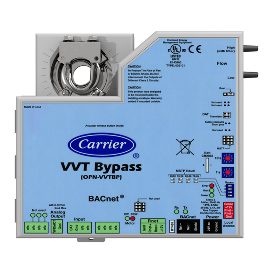
Introduction What is a VVT Bypass Controller? The VVT Bypass Controller (#OPN-VVTBP), a component of the i-Vu Open Control System, regulates the supply duct static pressure by controlling one of the following: • The system's bypass damper The controller's built-in damper actuator provides 35 in/lbs of torque. If the built-in actuator's torque is insufficient, the VVT Bypass Controller can be used to drive an external high-torque actuator. - Page 6 Not used Analog Conductors Only Rnet+ CW CCW Output BACnet Power Input R n e t Local Motor Access NOTE This document gives instructions for field-installation of a VVT Bypass Controller in an i-Vu Open Control System. VVT Bypass Controller...
-
Page 7: Specifications
LED's indicate status of communications, running, errors, power, and digital outputs Environmental operating 0 to 130° F (-18 to 54°C), 0 to 90% relative humidity, non-condensing range Storage temperature range -24 to 140°F (-30 to 60°C), 0 to 90% relative humidity, non-condensing VVT Bypass Controller... -
Page 8: Safety Considerations
The equipment should be operated and serviced only by authorized personnel who have a thorough knowledge of system operation, safety devices, and emergency procedures. Good judgment should be used in applying any manufacturer's instructions to avoid injury to personnel or damage to equipment and property. VVT Bypass Controller... - Page 9 Disconnect all power to the unit before performing maintenance or service. Unit may automatically start if power is not disconnected. Follow all local, state, and federal laws regarding disposal of equipment containing hazardous materials such as mercury contactors. VVT Bypass Controller...
-
Page 10: Installation
Set the controller's address (page 10). Wire the controller to the MS/TP network (page 10). Connect the inputs and outputs (page 11). Field-supplied hardware Each VVT Bypass Controller installation requires the following field-supplied components: • damper • damper actuator (if high-torque actuator or slaved dampers are required) •... -
Page 11: Mounting The Vvt Bypass Controller
Installation Mounting the VVT Bypass Controller Mount the VVT Bypass Controller on the bypass duct damper actuator shaft. For service access, allow at least 1 foot (.3 m) of clearance between the front of the controller and adjacent surfaces. Allow 1 ft. (.3 m) clearance for service access 2.5 in. - Page 12 NOTE Tubing should be at least 2 feet long for stable airflow measurement. 11 Leave the controller's Low connector open for plenum return or to a room space if using ducted return. Tube installation High 12 Replace the controller’s cover. VVT Bypass Controller...
-
Page 13: Wiring The Vvt Bypass Controller For Power
Connect the transformer wires to the screw terminal connector. Apply power to the power supply. Measure the voltage at the VVT Bypass Controller’s power input terminals to verify that the voltage is within the operating range of 21.6–26.4 Vac. Connect a 4-inch (10.2 cm) wire from Gnd to earth ground. -
Page 14: To Address The Vvt Bypass Controller
Installation To address the VVT Bypass Controller You must give the VVT Bypass Controller an address that is unique on the network. You can address the VVT Bypass Controller before or after you wire it for power. If the VVT Bypass Controller has been wired for power, pull the screw terminal connector from the controller's power terminals labeled Gnd and 24 Vac. -
Page 15: Wiring Specifications
NOTE Use the same polarity throughout the network segment. Verify that the MSTP jumper is set to MSTP. Set DIP switches 1 and 2 to the appropriate baud rate. See the MSTP baud diagram on the VVT Bypass Controller. The default baud rate is 76.8 kbps. -
Page 16: Wiring A Duct Air Temperature Sensor To An Input
Wiring a Duct Air Temperature sensor to an input Part #33ZCSENDAT The VVT Bypass Controller must be connected to a Duct Air Temperature (DAT) sensor that monitors the temperature of the air delivered by the air source. NOTE This document gives instructions for wiring the sensor to the VVT Bypass Controller. For mounting and wiring the sensor, see the Carrier Sensors Installation Guide. -
Page 17: High-Torque Actuators
NOTE For proper operation and to prevent damage to the devices, use the same polarity for the actuator's power and the VVT Bypass Controller's power. Linked actuators You can wire up to 4 of the following Belimo actuators to the VVT Bypass Controller's analog output. Link actuators whose travel times and other parameters coincide. LMX24-MFT P-10028 45 in.-lb actuator with 0–10 Vdc control... - Page 18 Installation NOTE Maintain polarity if using the same power supply for more than one actuator. VVT Bypass Controller...
-
Page 19: Start-Up
Start-up Start-up To start up the VVT Bypass Controller, you need one of the following user interfaces. These items let you access the controller information, read sensor values, and test the controller. This interface... Provides a... i-Vu Open software Permanent interface... -
Page 20: Performing System Checkout
Performing system checkout Bypass damper Verify the VVT Bypass Controller is securely fastened to the bypass damper shaft and duct work. Verify duct air temperature sensor is installed at the inlet of the damper or in the air source supply duct upstream of the bypass damper connection. -
Page 21: Variable Frequency Drive (Vfd)
• In the i-Vu or Field Assistant tree, select the RTU Open controller. Go to Properties > Equipment > Configuration > Service Configuration > Service Test, then enable Fan Test. Make sure all other outputs under Service Test are disabled. VVT Bypass Controller... - Page 22 • In the i-Vu or Field Assistant tree, select the RTU Open controller. Go to Properties > Equipment > Configuration > Service Configuration > Service Test, then disable Service Test and Fan Test. Make sure all other outputs under Service Test are disabled. VVT Bypass Controller...
-
Page 23: Sequence Of Operation
The controller can operate as part of a linked VVT system or as a stand-alone controller. Duct static pressure control The VVT Bypass Controller modulates a bypass damper or VFD to maintain the static pressure in the supply duct of the pressure-dependent VVT system. The controller has a built-in damper actuator that provides 35 in/lbs of torque. -
Page 24: Equipment Fan Off Detection
Maximum Heating SAT or below the configured Minimum Cooling SAT for more than 5 minutes. Airside linkage When the VVT Bypass Controller is part of a linked system, it uses data received through Linkage (equipment SAT and mode) to detect excessive leaving air temperature (LAT) conditions at the equipment and equipment operating mode. -
Page 25: Troubleshooting
Troubleshooting Troubleshooting If you have problems mounting, wiring, or addressing the VVT Bypass Controller, contact Carrier Control Systems Support. LED's The LED's on the VVT Bypass Controller show the status of certain functions. If this LED is on... Status is... -
Page 26: Serial Number
Module Status report (modstat) from your user interface Replacing the VVT Bypass Controller's battery The VVT Bypass Controller's 10-year Lithium CR2032 battery provides a minimum of 10,000 hours of data retention during power outages. If the VVT Bypass Controller experiences a power outage and the control program stops functioning, replace the battery. -
Page 27: Compliance
ASHRAE. ASHRAE does not endorse, approve or test products for compliance with ASHRAE standards. Compliance of listed products to requirements of ASHRAE Standard 135 is the responsibility of the BACnet manufacturers Association (BMA). BTL ® is a registered trademark of the BMA. VVT Bypass Controller... -
Page 28: Appendix A: Vvt Bypass Controller Points/Properties
Appendix A: VVT Bypass Controller Points/Properties Appendix A: VVT Bypass Controller Points/Properties Status Navigation: i-Vu / Field Assistant: Properties Equipment Status > > BACview: HOME STATUS > Point Name/Description Range Static Pressure - Prime Variable – The current supply duct static pressure. This 0 to 2.0 in. - Page 29 Appendix A: VVT Bypass Controller Points/Properties Point Name/Description Default/Range Minimum Cooling SAT – The minimum low limit value that the SAT must exceed to 45°F cause the static pressure setpoint to be set to the LAT Duct Static Pressure Setpoint.
-
Page 30: Maintenance
Appendix A: VVT Bypass Controller Points/Properties Point Name/Description Default/Range Supply Air Temp Calibration – A calibration offset value to allow the supply air -20 to 20°F temperature sensor to be adjusted to match a calibrated standard measuring the temperature in the same location. -
Page 31: Linkage
Appendix A: VVT Bypass Controller Points/Properties Linkage Navigation: i-Vu / Field Assistant: Properties Equipment Linkage > > BACview: HOME LINKAGE > Point Name/Description Range Air Linkage Status – If Active, the controller is part of a linked system. If Not Active Active/Not Active the controller is operating as a stand-alone device. -
Page 33: Index
Service Test • 16, 17 Inputs • 3, 12 Space Temperature - Prime Variable • 24 Wiring • 11 Static Pressure • 24, 26 i-Vu • 15, 16, 17, 24 Supply Air Temp Calibration • 24 Supply Air Temperature • 24 VVT Bypass Controller... - Page 34 Variable frequency drive (VFD) • 1, 17, 19, 24 Virtual BACview • 15 Weight • 3 Wiring Actuator • 12 Inputs • 3, 12 Output • 12 Wiring for power • 9 Wiring specifications Network • 11 Zero Cal • 16, 24 VVT Bypass Controller...
- Page 36 CARRIER CORPORATION ©2010 A member of the United Technologies Corporation family · Stock symbol UTX · Catalog No. 11-808-436-01 · 6/24/2010...
Need help?
Do you have a question about the VVT Bypass and is the answer not in the manual?
Questions and answers