Table of Contents
Advertisement
V
V
T
Z
o
n
e
I
I
C
o
n
t
r
o
l
l
e
r
V
V
T
Z
o
n
e
I
I
C
o
n
t
r
o
l
l
e
r
I
n
s
t
a
l
l
a
t
i
o
n
a
n
d
S
t
a
r
t
-
u
p
G
u
i
d
e
I
n
s
t
a
l
l
a
t
i
o
n
a
n
d
S
t
a
r
t
-
u
p
G
u
i
d
e
CARRIER CORPORATION ©2019
A member of the United Technologies Corporation family · Stock symbol UTX · Catalog No. 11-808-603-01 · 1/25/2019
Advertisement
Table of Contents

Related Manuals for Carrier VVT Zone II


Summary of Contents for Carrier VVT Zone II
- Page 1 CARRIER CORPORATION ©2019 A member of the United Technologies Corporation family · Stock symbol UTX · Catalog No. 11-808-603-01 · 1/25/2019...
- Page 2 Verify that you have the most current version of this document from www.hvacpartners.com or your local Carrier office. Important changes are listed in Document revision history at the end of this document. CARRIER CORPORATION ©2019. All rights reserved throughout the world. i-Vu is a registered trademark of Carrier...
-
Page 3: Table Of Contents
To wire ZS sensors to the controller ....................14 To wire the Wireless Adapter for wireless sensors ................15 To wire an Equipment Touch to the VVT Zone II ................17 To wire the TruVu™ ET Display ......................18 Wiring sensors to the VVT Zone II's inputs ..................... 19 Wiring specifications ........................... - Page 4 Alarms ................................. 86 Linkage ................................87 I/O Points ................................89 Appendix B: VVT terminal modes ..........................92 Appendix C: ZS Sensor display for VVT Zone II ....................... 94 Appendix D: BACnet points list ..........................95 Document revision history ............................98...
-
Page 5: Introduction
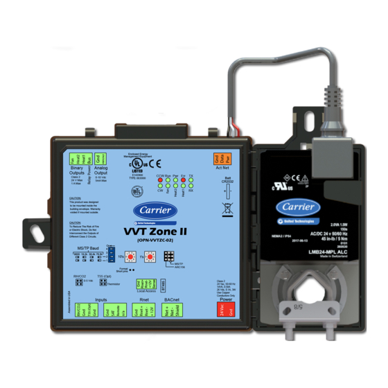
® ) applications. NOTE The VVT Zone II is available in both English or Metric units. The metric version has (-M) appended to the part number. Everything in this document applies to both versions. The VVT Zone II with actuator maintains zone temperature by operating the terminal fan and regulating the flow of conditioned air into the space. - Page 6 Introduction NOTE This document gives instructions for field-installation of a VVT Zone II in an i-Vu® Control System. However, VVT Zone IIs are available factory-mounted to Carrier’s round and rectangular dampers. Damper assemblies have an integrated duct temperature sensor. VVT Zone II Controller CARRIER CORPORATION ©2019...
-
Page 7: Specifications
Actuator Belimo brushless DC motor, torque 45 inch-pounds (5 Nm), runtime 154 seconds Act Net port To connect the actuator cable and the VVT Zone II BACnet port For communication with the controller network using BACnet ARC156 (156 kbps) or BACnet MS/TP (9600 bps – 76.8 kbps) Rnet port •... - Page 8 Profile as defined in ANSI/ASHRAE Standard 135-2012 (BACnet) Annex L, Protocol Revision 9 Listed by UL-916 (PAZX), cUL-916 (PAZX7), FCC Part 15-Subpart B, Class B, CE VVT Zone II Controller CARRIER CORPORATION ©2019 Installation and Start-up Guide All rights reserved...
-
Page 9: Safety Considerations
• 2 screws and 2 hollow wall anchors (to mount relative humidity sensor directly to wall) • valve and actuator for hot water heat (if required) VVT Zone II Controller CARRIER CORPORATION ©2019 Installation and Start-up Guide All rights reserved... -
Page 10: Installing The Vvt Zone Ii
Installing the VVT Zone II Installing the VVT Zone II To install the VVT Zone II: Mount the controller to the VVT box. (page 6) Wire the controller for power. (page 10) Set the controller's address. (page 12) Wire the controller to the BACnet MS/TP or BACnet ARC156 network. (page 12) Wire devices to the Rnet port. - Page 11 Installing the VVT Zone II Disconnect the actuator from the controller by inserting a screw driver in the slot on the back of the VVT Zone II and pressing the tab. The actuator cable or an attached extension cable must connect to the controller's Act Net port.
- Page 12 Center the bushing in the slot. Failure to do so may cause the actuator to stick or bind. ○ The VVT Zone II must be secured, but loose enough to allow movement. of the damper shaft. ○ VVT Zone II Controller CARRIER CORPORATION ©2019...
- Page 13 Installing the VVT Zone II CAUTIONS You must use the screws, anti-rotation slot's bushings, and o-rings that are shipped with the VVT Zone II. ○ Overtightening the screws so that the controller and actuator cannot move may damage the unit.
-
Page 14: Wiring The Vvt Zone Ii For Power
WARNING Do not apply line voltage (mains voltage) to the controller's ports and terminals. CAUTIONS • The VVT Zone II is powered by a Class 2 power source. Take appropriate isolation measures when mounting it in a control panel where non-Class 2 circuits are present. •... -
Page 15: To Wire The Controller For Power
Connect the transformer wires to the screw terminal connector. Apply power to the power supply. Measure the voltage at the VVT Zone II’s power input terminals to verify that the voltage is within the operating range of 21.6–26.4 Vac. Connect a 4-inch (10.2 cm) wire from Gnd to the control panel. -
Page 16: Addressing The Vvt Zone Ii
Installing the VVT Zone II Addressing the VVT Zone II You must give the VVT Zone II an address that is unique on the network. You can address the VVT Zone II before or after you wire it for power. -
Page 17: To Wire The Controller To The Bacnet Network
NOTE Use the same baud rate for all controllers on the network segment. If the VVT Zone II is at either end of a network segment, connect a BT485 to the VVT Zone II. Insert the power screw terminal connector into the VVT Zone II's power terminals. -
Page 18: Wiring Specifications
.25 in. Inner insulation (.6 cm) Wire each terminal on the sensor to the same terminal on the controller. See diagram below. NOTE Carrier recommends that you use the following Rnet wiring scheme: Connect this wire... To this terminal... +12V... -
Page 19: To Wire The Wireless Adapter For Wireless Sensors
To wire the Wireless Adapter for wireless sensors WARNING Do not apply line voltage (mains voltage) to the Wireless Adapter. The Carrier wireless sensors are available in 868, 902, and 928 MHz radio frequency. The sensors are thermistor- based temperature sensors that may optionally sense humidity. - Page 20 Installing the VVT Zone II Wire the Rnet +, Rnet -, and Gnd terminals on the controller's Rnet port to the terminals of the same name on the Wireless Adapter's Rnet connector. NOTE If using shielded wire, connect the shield wire and the ground wire to the Gnd terminal.
-
Page 21: To Wire An Equipment Touch To The Vvt Zone Ii
Partially cut, then bend and pull off the outer jacket of the cable. Do not nick the inner insulation. Strip about 0.25 inch (0.6 cm) of the inner insulation from each wire. Wire the VVT Zone II's Rnet+ and Rnet- terminals to the terminals of the same name on the Equipment Touch's connector. -
Page 22: To Wire The Truvu™ Et Display
Wire the TruVu™ ET Display 24V DC connector to the 24 Vdc power supply using 2-conductor 18 AWG wire. Maximum distance 100 feet (30 meters). CAUTION The TruVu™ ET Display can share a power supply with the Carrier controller as long as: •... -
Page 23: Wiring Sensors To The Vvt Zone Ii's Inputs
NOTE This document gives instructions for wiring the sensors to the VVT Zone II. For detailed installation instructions, see the device's Installation Guide. WARNING Disconnect electrical power to the VVT Zone II before wiring it. Failure to follow this warning could cause electrical shock, personal injury, or damage to the controller. -
Page 24: To Wire The T55 Sensor To The Controller
Part #33ZCSENSAT Each VVT Zone II requires that a temperature sensor be installed in the supply air stream. Mount the SAT sensor at least 2 feet downstream from a hot water or steam coil, or at least 4 feet downstream from an electric heating coil. -
Page 25: To Wire A Duct Air Sensor To The Controller
#33ZCSPTCO2 Wire the sensor to the controller. See appropriate diagram below. Verify that the RH/CO2 jumper is set to 0-5 Vdc on the VVT Zone II. Verify the J7 jumper on the sensor is set to 0-5 Vdc. VVT Zone II Controller CARRIER CORPORATION ©2019... - Page 26 Wire the sensor to the controller. See appropriate diagram below. Install a field supplied 250 Ohm 1/4 watt 2% tolerance resistor across the controller's RH/CO2 and Gnd terminals. Verify that the RH/CO2 jumper is set to 0-5Vdc on the VVT Zone II. VVT Zone II Controller CARRIER CORPORATION ©2019...
-
Page 27: To Wire The Relative Humidity Sensor To The Controller
Installing the VVT Zone II Wiring diagram for #33ZCT55CO2: To wire the Relative Humidity sensor to the controller Part #33ZCSENSRH-02 The Relative Humidity (RH) sensor is used for zone humidity control (dehumidification) if the rooftop unit has a dehumidification device. If not, the sensor only monitors humidity. -
Page 28: Wiring A Remote Occupancy Sensor
Set SW3 on the sensor as shown below. Wiring a remote occupancy sensor You can wire a normally open or normally closed dry-contact occupancy sensor to the VVT Zone II's REMOTE input as shown below. The controller supplies the voltage needed for the input. -
Page 29: Wiring Equipment To Outputs
Fan box 2-stage electric heat (page 36) Wiring field-supplied actuators to the analog output (page 37) WARNING Disconnect electrical power to the VVT Zone II before wiring it. Failure to follow this warning could cause electrical shock, personal injury, or damage to the controller. -
Page 30: Wiring Diagram Legend
Installing the VVT Zone II Wiring diagram legend Ground Hot water valve Supply air temperature sensor Silicon controlled rectifier Space temp ZS sensors or Wireless Adapter for sensor wireless sensors T55 (OPT) Alternate space temperature sensor – – – Field-supplied wiring... -
Page 31: Single Duct 2-Position Hot Water
Installing the VVT Zone II Single duct 2-position hot water VVT Zone II Controller CARRIER CORPORATION ©2019 Installation and Start-up Guide All rights reserved... -
Page 32: Single Duct Modulating Hot Water
Installing the VVT Zone II Single duct modulating hot water VVT Zone II Controller CARRIER CORPORATION ©2019 Installation and Start-up Guide All rights reserved... -
Page 33: Single Duct Scr Electric Heat
Installing the VVT Zone II Single duct SCR electric heat VVT Zone II Controller CARRIER CORPORATION ©2019 Installation and Start-up Guide All rights reserved... -
Page 34: Single Duct Combination Base Board And Ducted Heat
Installing the VVT Zone II Single duct combination base board and ducted heat VVT Zone II Controller CARRIER CORPORATION ©2019 Installation and Start-up Guide All rights reserved... -
Page 35: Single Duct Staged Electric Heat
Installing the VVT Zone II Single duct staged electric heat VVT Zone II Controller CARRIER CORPORATION ©2019 Installation and Start-up Guide All rights reserved... -
Page 36: Fan Box 2-Position Hot Water
Installing the VVT Zone II Fan box 2-position hot water VVT Zone II Controller CARRIER CORPORATION ©2019 Installation and Start-up Guide All rights reserved... -
Page 37: Fan Box Modulating Hot Water - Ducted Or Baseboard
Installing the VVT Zone II Fan box modulating hot water - ducted or baseboard VVT Zone II Controller CARRIER CORPORATION ©2019 Installation and Start-up Guide All rights reserved... -
Page 38: Fan Box Scr Electric Heat
Installing the VVT Zone II Fan box SCR electric heat VVT Zone II Controller CARRIER CORPORATION ©2019 Installation and Start-up Guide All rights reserved... -
Page 39: Fan Box Combination Baseboard And Ducted Heat
Installing the VVT Zone II Fan box combination baseboard and ducted heat VVT Zone II Controller CARRIER CORPORATION ©2019 Installation and Start-up Guide All rights reserved... -
Page 40: Fan Box 2-Stage Electric Heat
Installing the VVT Zone II Fan box 2-stage electric heat VVT Zone II Controller CARRIER CORPORATION ©2019 Installation and Start-up Guide All rights reserved... -
Page 41: Wiring Field-Supplied Actuators To The Analog Output
You can wire a high-torque actuator or parallel actuators to the controller's 0–10 Vdc analog output. High-torque actuator You can wire one of the following Belimo actuators to the VVT Zone II's analog output instead of using the controller's built-in, 45 in.-lb (4 Nm) actuator. - Page 42 Installing the VVT Zone II Linked actuators You can wire up to 4 of the following Belimo actuators to the VVT Zone II's analog output. Use like actuators so that travel times and other parameters coincide. LMX24-MFT P-10028 45 in.-lb (5 Nm) actuator with 0–10 Vdc control NMX24-MFT P-10028 90 in.-lb (10 Nm) actuator with 0–10 Vdc control...
- Page 43 Installing the VVT Zone II IMPORTANT! If slaving 45° actuators, you must go to Properties > I/O Points > Hot Water Valve Max and change scaling to 200 for the slave actuator to correctly track the primary actuator. NOTE Maintain polarity if using the same power supply for more than one actuator.
-
Page 44: Start-Up
Configuring the VVT Zone II's properties To start up the VVT Zone II, you must configure certain points and properties. Appendix A (page 65) is a complete list of all the points and properties, with descriptions, defaults, and ranges. These properties affect the unit operation and/or control. -
Page 45: Configuring Zs Sensors
Start-up Configuring ZS Sensors The VVT Zone II automatically detects 1 ZS temperature sensor set to address (1). This sensor is labeled Main ZS Sensor. You must configure the ZS Sensor properties in the i-Vu® application or Field Assistant as follows: •... -
Page 46: Commissioning The Vvt Zone Ii
Start-up Commissioning the VVT Zone II Using Field Assistant or the i-Vu application: Calibrate the damper travel. Go to Properties > Configuration > Service Configuration > Pressure Dependent Control > Details tab > Test and Balance. Click Calibrated Damper Close and verify it goes to the closed position. -
Page 47: Step 1: Prepare For Balancing
Fan's Lock value to checkbox, then select On in the droplist. Click Apply. See the zone terminal manufacturer's instructions on adjusting the fan speed to meet design airflow requirements. When finished, clear the Fan's Lock value to checkbox. VVT Zone II Controller CARRIER CORPORATION ©2019 Installation and Start-up Guide... -
Page 48: Step 3: Set The System Static Pressure
For each zone noted in step 1, go to Properties > Control Program > Configuration > Service Configuration > Pressure Dependent Control > Details tab. Click Cool Max or Heat Max (whichever has the highest design max airflow) to force the damper to its maximum open position. VVT Zone II Controller CARRIER CORPORATION ©2019 Installation and Start-up Guide... - Page 49 CAUTION You must complete steps 4 and 5 to prevent loss of temperature control to the space and to maintain normal operation of the system. VVT Zone II Controller CARRIER CORPORATION ©2019 Installation and Start-up Guide...
-
Page 50: Sequence Of Operation
Sequence of operation Sequence of operation The VVT Zone II supports 3 types of pressure-dependent terminal configurations: • Single duct • Series fan-powered • Parallel fan-powered The controller can operate as part of a linked VVT system or as a stand-alone controller. -
Page 51: Zone Airflow Control
See Appendix B: VVT terminal modes (page 92). Damper Actuator(s) – The VVT Zone II's built-in 35 in/lb (4 Nm) actuator has a 205 second full travel time for 90° operation. For field retrofit applications, the actuator can be adjusted for a damper stroke between 30° and 90°, and it can be configured to move clockwise (default) or counterclockwise. -
Page 52: Zone Reheat Control
Sequence of operation Zone reheat control The VVT Zone II can be configured for one of the following Heat Types to meet the zone's heating requirements: • Modulating Hot Water/Steam • Modulating SCR Electric • Two Position Hot Water/Steam •... -
Page 53: Demand Control Ventilation (Dcv) And Dehumidification Using Optional Sensors
Demand control ventilation (DCV) and dehumidification using optional sensors The VVT Zone II’s RH/CO2 input supports an optional CO sensor or Relative Humidity (RH) sensor. The sensor can have a 5-volt maximum output. The range is configurable as either 0–5 or 1–5 volts (1–5 volt supports 4–20 mA sensors with a 250 ohm resistor). -
Page 54: Occupancy
A local schedule set up directly in the controller using a touchscreen device or Field Assistant. • A network schedule from an i-Vu internal router. The VVT Zone II must be networked to an i-Vu Open Router or an i-Vu internal router. -
Page 55: Alarms
Sequence of operation Alarms Space Temp Sensor Alarm – The VVT Zone II monitors each space temperature sensor and the network input for space temperature. If no valid space temperature value is available, the controller generates an alarm and disables all local heating or cooling. The controller modulates the damper to the minimum heat, minimum cool, or ventilation position based on the air source mode. -
Page 56: Demand Limiting
3 levels of consumption. With the expanded setpoints, the equipment works less, thereby saving energy. If the VVT Zone II receives a demand limit signal through the network, it expands its setpoints based on the demand level. The default amounts are: •... - Page 57 This information, plus the occupancy status, is sent to the air source so that its current mode is disabled and the unit ceases heating or cooling operation. If the system is occupied, the air source fan and OA damper, if applicable, operate to maintain proper ventilation. VVT Zone II Controller CARRIER CORPORATION ©2019 Installation and Start-up Guide...
-
Page 58: Linkage Modes And Operation
(4.4 °C) more than the space temperature. In all cases, Heat mode is maintained until the SAT drops 2 °F (1.1 °C) below the space temperature. VVT Zone II Controller CARRIER CORPORATION ©2019 Installation and Start-up Guide All rights reserved... - Page 59 The zone’s local heat has not operated for at least 5 minutes, the current mode is not Heat or Vent, and the SAT is less than 65°F (18.3°C). See Appendix B: VVT terminal modes (page 92). VVT Zone II Controller CARRIER CORPORATION ©2019 Installation and Start-up Guide...
-
Page 60: To Adjust The Driver Properties
Use the following if you want to change the driver's properties in the i-Vu® interface. On the i-Vu® navigation tree, right-click the VVT Zone II and select Driver Properties. Make changes as needed on the Properties page for Driver and any of its children. -
Page 61: Device
• VVT Zone II network communication Configuration NOTE The three APDU fields refer to all networks over which the VVT Zone II communicates. Max Masters and Max Info Apply only if the VVT Zone II is on an MS/TP network. -
Page 62: Notification Classes
Select to have a device continue sending an alarm message until it receives Notifications delivery confirmation from the recipient. Transitions to Send Uncheck the types of alarms you do not want the recipient to get. VVT Zone II Controller CARRIER CORPORATION ©2019 Installation and Start-up Guide All rights reserved... -
Page 63: Calendars
Template Enable Clear these checkboxes to disable Alarm or Return to normal messages of this type from this controller. Notification Class Do not change this field. VVT Zone II Controller CARRIER CORPORATION ©2019 Installation and Start-up Guide All rights reserved... -
Page 64: Specific Events
NOTE See To get the Carrier VVT Zone II serial number (page 62) for the controller serial number. The Act Net network shows the VVT Zone II’s actuator has Address 1. -
Page 65: Troubleshooting
NOTE To help you troubleshoot, obtain a Module Status (Modstat) from the controller and review the System Error and Warning details. LED's The LED's on the VVT Zone II show the status of certain functions. Verify the LED patterns by cycling power to the controller and noting the lights and flashes. If this LED is on... -
Page 66: To Get The Serial Number
NOTE If you resolve the issue but the Error LED does not turn off, cycle power to the controller. To get the serial number If you need the VVT Zone II's serial number when troubleshooting, the number is on a Module Status report (Modstat) under Core (or Main) board hardware To obtain a modstat in the i-Vu®... -
Page 67: To Restore Factory Defaults
To replace the battery If the VVT Zone II experiences a power outage and the control program stops functioning, replace the battery. You need to replace the battery if the voltage measures below 2.9 volts when the controller is not powered. -
Page 68: Compliance
BACnet Compliance Compliance of listed products to requirements of ASHRAE Standard 135 is the responsibility of BACnet International. BTL ® is a registered trademark of BACnet International. VVT Zone II Controller CARRIER CORPORATION ©2019 Installation and Start-up Guide All rights reserved... -
Page 69: Appendix A: Vvt Zone Ii Points/Properties
Appendix A: VVT Zone II Points/Properties Appendix A: VVT Zone II Points/Properties NOTE Engineering units shown in this document in the defaults and ranges are strictly for reference. You must enter an integer only. Status Navigation: i-Vu® / Field Assistant:... -
Page 70: Unit Configuration
Appendix A: VVT Zone II Points/Properties Unit Configuration Navigation: i-Vu® / Field Assistant: Properties Control Program Configuration Unit Configuration > > > Point Name/Description Default/Range Heat Enable – Enables the reheat function. Enable Disable/Enable Parallel Fan Heat On Delay – The delay in reheat coming on after the zone has a 15 minutes heating demand. - Page 71 Appendix A: VVT Zone II Points/Properties Point Name/Description Default/Range Power Fail Restart Delay – How long the controller delays normal operation after the 60 seconds power is restored. This is typically used to prevent excessive demand when recovering 0 to 600 secs from a power failure.
-
Page 72: Setpoints
Appendix A: VVT Zone II Points/Properties Setpoints Navigation: i-Vu® / Field Assistant: Properties Control Program Configuration Setpoints > > > Select a color band on the setpoint graph to see the current setpoints in the Heating and Cooling fields. The values in this graphic are Fahrenheit. - Page 73 Appendix A: VVT Zone II Points/Properties Default Range: -40 to 245°F (-40 to 118.3°C) Demand Level Point Name/Description Occupied Occupied Heating 1 – Light Blue 69°F 68°F 67°F 65°F The space temperature must be less than the Occupied Heating (20.5°C) (20°C)
- Page 74 Appendix A: VVT Zone II Points/Properties Point Name/Description Default/Range Unoccupied Heating 2 – Dark Blue 52°F (11.1°C) The space temperature must be less than the Unoccupied Heating 2 setpoint to 40 to 90°F generate an unoccupied low space temperature alarm. We recommend that this value (4.4 to 32.2°C)
- Page 75 Appendix A: VVT Zone II Points/Properties Hysteresis – The desired difference between the temperature at which the zone color .5 °F ( .27 °C) changes as the zone temperature departs from the acceptable range between the 0.2 to 1.0 °F heating and cooling setpoints (green) into the Cooling 1 (yellow) or Heating 1 (light blue) (.1 to .5 °C)
- Page 76 Appendix A: VVT Zone II Points/Properties Point Name/Description Range English Metric LtBlue – The amount the zone’s learned heating capacity is adjusted when the Learning 0.0600 .0333 Adaptive Optimal Start algorithm runs, when the zone’s thermographic color at 0 to 1 occupancy is light blue.
- Page 77 Appendix A: VVT Zone II Points/Properties Optimal Start Type – The method used to change from unoccupied to occupied Temperature setpoint. Compensated Options: None None* – Unit will not change to occupied setpoint until the scheduled time or the unit Temperature goes into an occupied mode.
- Page 78 Appendix A: VVT Zone II Points/Properties To configure setpoint properties for ZS or wireless sensors, CTRL+click anywhere on the Zone Setpoints: graph at the top of the Setpoints section in order to access the Properties microblock popup. In the popup, on the Properties > Sensor tab, configure ZS or wireless sensors for Setpoint Adjust.
-
Page 79: Alarm Configuration
Appendix A: VVT Zone II Points/Properties Alarm Configuration Navigation: i-Vu® / Field Assistant: Properties Control Program Configuration Alarm Configuration > > > Point Name/Description Default/Range Space Temperature Alarm Occupied Alarm Hysteresis – This value is added to the effective cooling setpoints and 5 °F (2.7 °C) - Page 80 Appendix A: VVT Zone II Points/Properties Point Name/Description Default/Range IAQ/Ventilation Alarm 1100ppm Occupied High CO2 Alarm Limit – The value that the CO sensor must exceed to generate an Indoor Air Quality Alarm in the occupied mode if DCV Control is set to 0 to 9999 ppm Enable.
-
Page 81: Service Configuration
Appendix A: VVT Zone II Points/Properties Service Configuration Navigation: i-Vu® / Field Assistant: Properties Control Program Configuration Service Configuration > > > Point Name/Description Default/Range Terminal Type – The type of zone terminal that the controller is installed on. Single Duct... - Page 82 Appendix A: VVT Zone II Points/Properties Point Name/Description Default/Range Hardwired Sensor – The type of sensor used on the controller's RH/CO2 hardwire input. None This setting determines the control channel input function. None Options: RH Sensor RH Sensor – Relative humidity for zone dehumidification IAQ Sensor IAQ Sensor –...
- Page 83 Appendix A: VVT Zone II Points/Properties Point Name/Description Default/Range Direction Clockwise – If Damper Actuator is set to Built-in actuator, set this field Close to the damper's position when it rotates clockwise. Close/Open Target Damper Position - The current damper position. To override normal 0 to 100% control for troubleshooting purposes, select Lock value to and then enter a value.
- Page 84 Appendix A: VVT Zone II Points/Properties Point Name/Description Default/Range Test and Balance – Use the following command buttons when commissioning a zone, balancing the system (page 42), replacing the zone controller, or troubleshooting. If Automatic Control is not selected within 4 hours, the controller will resume normal control.
- Page 85 Appendix A: VVT Zone II Points/Properties Zone Temp - Configure additional ZS or wireless temperature sensors used on the VVT (Index) Area - (1) Main Zone II. Sensor Use - checked Calibration - 0 Combination Algorithm - Average Input Smoothing - None...
- Page 86 Appendix A: VVT Zone II Points/Properties (Index) Area - (1) Main ZS ZS Zone CO2 - Configure additional ZS CO sensors used on the VVT Zone II. Sensor Use - unchecked Calibration - 0 Combination Algorithm - Maximum Input Smoothing -...
-
Page 87: Maintenance
Appendix A: VVT Zone II Points/Properties System Space RH – The relative humidity received over the network. -999 indicates no 2 to 100% value has been received and it will not be used. System Space AQ – The indoor air quality received over the network. -999 indicates no 300 to 9999 ppm value has been received and it will not be used. - Page 88 Appendix A: VVT Zone II Points/Properties Point Name/Description Default/Range Effective Cool Setpoint – The current cooling setpoint. May include offsets from _°F/C configured occupied/unoccupied setpoints resulting from Optimal Start to Demand Limit. Relative Humidity Source – The source of the relative humidity value.
- Page 89 Appendix A: VVT Zone II Points/Properties Point Name/Description Default/Range BAS On/Off – Determines the occupancy state of the controller and can be set over the Inactive network by another device or third party BAS. Inactive Options: Occupied Unoccupied Inactive – Occupancy is determined by a configured schedule.
-
Page 90: Alarms
Appendix A: VVT Zone II Points/Properties Alarms Navigation: i-Vu® / Field Assistant: Properties Control Program Alarms > > Point Name/Description Range Space Temperature Alarm – Indicates if the space temperature exceeds the high or low Normal/Alarm alarm limit. Alarming Temperature – Indicates the space temperature value that caused the space -56 to 245°F... -
Page 91: Linkage
Appendix A: VVT Zone II Points/Properties Linkage Navigation: i-Vu® / Field Assistant: Properties Equipment Linkage > > Point Name/Description Default/Range Airside Linkage Click Linkage Collector/Linkage Provider to access the microblock popup's Summary and Details tabs. See the microblock popup's Help for more detailed explanations. - Page 92 Appendix A: VVT Zone II Points/Properties Point Name/Description Default/Range System Mode Reselect Timer (minutes) – Applies only to a VVT master. Defines how long the system continues to operate in the current mode before it reassesses all zones 10 to 120 while the current demand is still active.
-
Page 93: I/O Points
Appendix A: VVT Zone II Points/Properties I/O Points Navigation: i-Vu® / Field Assistant: Properties I/O Points > WARNINGS • Do not change the Value, Offset/Polarity, Exp:Num, I/O Type, Sensor/Actuator Type, Min/Max, or Resolution I/O configuration parameter for the points listed below. Changing these parameters could cause improper control and/or equipment damage. - Page 94 Appendix A: VVT Zone II Points/Properties Point Name/Description Default/Range Object Name - Do not change. zone_temp CO2 Sensor – The current voltage of the controller's RH/CO2 input. 0 to 5 Vdc RH Sensor – The current voltage of the controller's RH/CO2 input.
- Page 95 Appendix A: VVT Zone II Points/Properties Input Smoothing – If the raw value from the sensor changes frequently, you Medium can select one of the following options to send out an average of several readings on the output wire. None •...
-
Page 96: Appendix B: Vvt Terminal Modes
Series Fan Heating Minimum Damper Position Disable Enable (Cool) Single Duct Reheat Minimum Damper Position Enable Series or Heating Minimum Damper Position Enable Enable Parallel Fan (Cool) VVT Zone II Controller CARRIER CORPORATION ©2019 Installation and Start-up Guide All rights reserved... - Page 97 Pressurize Maximum Damper Position Disable Disable Parallel Fan (Cool) Series Fan Pressurize Maximum Damper Position Disable Enable (Cool) Evacuation/ Evacuate Close Damper Disable Disable Shutdown (Linked) VVT Zone II Controller CARRIER CORPORATION ©2019 Installation and Start-up Guide All rights reserved...
-
Page 98: Appendix C: Zs Sensor Display For Vvt Zone Ii
Appendix C: ZS Sensor display for VVT Zone II Appendix C: ZS Sensor display for VVT Zone II Property ZS Screen Rnet Tag Description Rnet Text Active Alarms Diagnostic 1550 -nonE No Active Alarms StP-AL Zone Temp Alarm SPco2-AL Zone CO2 Alarm... -
Page 99: Appendix D: Bacnet Points List
System Outdoor Air Temperature °F -999 system_oat AV:1901 System Setpoint Adjustment °F -999 system_stpt_adj AV:1913 System Space AQ -999 system_iaq AV:1903 System Space RH -999 system_rh AV:1904 VVT Zone II Controller CARRIER CORPORATION ©2019 Installation and Start-up Guide All rights reserved... - Page 100 MSV:2006 2=Heating 3=Warm-Up 4=Vent 5=N/A 6=Cooling 7=Dehumidify 8=Reheat 9=Pressurize 10=Evacuate 11=Shutdown 12=IAQ Override 13=Air Balancing 1=Single Duct Terminal Type terminal_type MSV:2007 2=Parallel Fan 3=Series Fan VVT Zone II Controller CARRIER CORPORATION ©2019 Installation and Start-up Guide All rights reserved...
- Page 101 BV:7004 1=Alarm 0=Normal Wireless Battery Strength Alarm ws_batt_alarm BV:7064 1=Alarm Wireless Signal Strength Alarm 0=Normal ws_sig_alarm BV:7065 1=Alarm ZS/WS Sensor Configuration 0=Normal zs_config_fail BV:7055 1=Alarm VVT Zone II Controller CARRIER CORPORATION ©2019 Installation and Start-up Guide All rights reserved...
-
Page 102: Document Revision History
Mounting the VVT Zone II > To mount Added caution stating that you must use the bushing, O-ring, X-H-RE-E-CC-JS the controller and actuator and screws that are shipped with the VVT Zone II, along with applicable graphic. 10/30/18 Wiring equipment to the VVT Zone II's Removed SPT sensors. - Page 104 CARRIER CORPORATION ©2019 A member of the United Technologies Corporation family · Stock symbol UTX · Catalog No. 11-808-603-01 · 1/25/2019...
Need help?
Do you have a question about the VVT Zone II and is the answer not in the manual?
Questions and answers