Table of Contents
Advertisement
Quick Links
CONTENTS
SAFETY CONSIDERATIONS . . . . . . . . . . . . . . . . . . . . . . . . . . . .1
GENERAL . . . . . . . . . . . . . . . . . . . . . . . . . . . . . . . . . . . . . . . . . . . . . 1
INSTALLATION . . . . . . . . . . . . . . . . . . . . . . . . . . . . . . . . . . . . . 1-11
General . . . . . . . . . . . . . . . . . . . . . . . . . . . . . . . . . . . . . . . . . . . . . . . . 1
Bypass Controller Hardware . . . . . . . . . . . . . . . . . . . . . . . . . . . 2
Field-Supplied Hardware. . . . . . . . . . . . . . . . . . . . . . . . . . . . . . . 2
Mount Bypass Controller . . . . . . . . . . . . . . . . . . . . . . . . . . . . . . 2
• LOCATION
• MOUNTING
Connect the Power Transformer . . . . . . . . . . . . . . . . . . . . . . . .2
Bypass Controller Inputs and Outputs . . . . . . . . . . . . . . . . . 5
Install Duct Temperature Sensor. . . . . . . . . . . . . . . . . . . . . . . 5
Install Pressure Tubing . . . . . . . . . . . . . . . . . . . . . . . . . . . . . . . . 5
Install Field-Supplied Actuators . . . . . . . . . . . . . . . . . . . . . . . .6
Damper Stops . . . . . . . . . . . . . . . . . . . . . . . . . . . . . . . . . . . . . . .6
Connect the Carrier Network Communication Bus . . . . . 6
START-UP. . . . . . . . . . . . . . . . . . . . . . . . . . . . . . . . . . . . . . . . . . . . . 12
Perform System Checkout . . . . . . . . . . . . . . . . . . . . . . . . . . . . 12
CONFIGURATION . . . . . . . . . . . . . . . . . . . . . . . . . . . . . . . . . . 12-17
Status Display Table . . . . . . . . . . . . . . . . . . . . . . . . . . . . . . . . . . 12
Maintenance Tables. . . . . . . . . . . . . . . . . . . . . . . . . . . . . . . . . . . 13
MAINTENANCE TABLE
Configuration Tables . . . . . . . . . . . . . . . . . . . . . . . . . . . . . . . . . 15
TABLE
OPERATION . . . . . . . . . . . . . . . . . . . . . . . . . . . . . . . . . . . . . 18-20
System Pressure Operation . . . . . . . . . . . . . . . . . . . . . . . .18
Bypass Controller Calibration . . . . . . . . . . . . . . . . . . . . . .18
SAFETY CONSIDERATIONS
SAFETY NOTE
Air-conditioning equipment will provide safe and reli-
able service when operated within design specifications.
The equipment should be operated and serviced only by
authorized personnel who have a thorough knowledge
of system operation, safety devices and emergency
procedures.
Good judgement should be used in applying any manu-
facturer's instructions to avoid injury to personnel or dam-
age to equipment and property.
Manufacturer reserves the right to discontinue, or change at any time, specifications or designs without notice and without incurring obligations.
PC 111
Book 1
4
Tab
11a 13a
Installation, Start-Up and
Configuration Instructions
Part Number 33ZCBC-01
Page
Catalog No. 533-30012
3V™ Control System
VVT® Bypass Controller
Disconnect all power to the unit before performing mainte-
nance or service. Unit may automatically start if power is
not disconnected. Electrical shock and personal injury
could result.
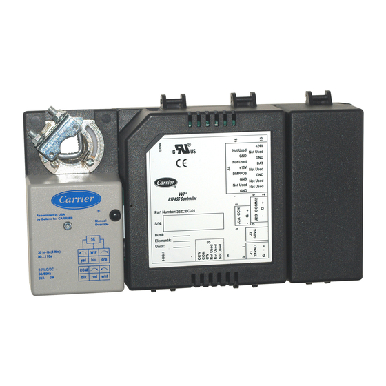
The 3V control system VVT bypass controller (33ZCBC-01)
is a system static pressure controller that operates to maintain the
desired system duct pressure based on the system pressure set
point. The VVT bypass controller is used with a system of VVT
zone controllers. Zone controllers maintain precise temperature
control in the space by regulating the flow of conditioned air into
the space and operating an optional terminal fan.
As part of the 3V control system, the bypass controller is
designed to communicate using a Carrier protocol with a
Linkage Coordinator zone controller. One Linkage Coordina-
tor zone controller can coordinate up to 31 additional zone
controllers. The purpose of the Linkage Coordinator/zone
relationship is to provide an efficient data path for communica-
tion between the zone controllers, bypass controller, and
associated Carrier network air source. This arrangement makes
up the 3V control system.
A user interface is not required for everyday operation of
the bypass controller. A service person or building owner can
configure or operate the bypass controller through a Carrier
network user interface such as the System Pilot or Carrier
software.
General -
The bypass controller is used to control the
bypass damper actuator in the 3V control system. The purpose
of the bypass damper is to account for fluctuations in the sup-
ply air pressure caused by the zone dampers modulating to sat-
isfy individual set points. The bypass system allows a constant
volume HVAC (heating, ventilation and air conditioning) unit
to supply variable volumes of air to the building. The system
bypasses air from the supply side to the return side of the unit.
Determining the proper size for the bypass damper is criti-
cal for the operation of the VVT (variable volume/variable
temperature) system. If the damper selected is too large, it may
have to modulate more than necessary to react to system pres-
sure changes. The ability of the system to stay within a pressure
range is compromised. When the damper is undersized, the
capability of the damper to control the pressure may be com-
promised due to the inability to bypass enough air volume. An
undersized damper also creates higher airflow velocities which
add to the noise generated by the system.
Printed in U.S.A.
Form 33ZC-14SI
GENERAL
INSTALLATION
Pg 1
10-04
33ZC
Replaces: New
Advertisement
Table of Contents

Subscribe to Our Youtube Channel
Related Manuals for Carrier VVT 33ZC


Summary of Contents for Carrier VVT 33ZC
-
Page 1: Table Of Contents
Damper Stops ........6 designed to communicate using a Carrier protocol with a Connect the Carrier Network Communication Bus ..6 Linkage Coordinator zone controller. One Linkage Coordina- •... -
Page 2: Installation
Be sure the floating grom- Carrier provides system software that can be used to design the met is in the center of the slot. FAILURE TO... - Page 3 Fig. 1 — Bypass Controller Details Fig. 2 — Bypass Controller Dimensions...
-
Page 4: Dat
DUCT TEMPERATURE SENSOR SUPPLY BYPASS DAMPER BYPASS DAMPER W/ACTUATOR TRANSFORMER BUILDING HIGH PRESSURE LOW PRESSURE TUBING OPEN TO SPACE POWER SUPPLY TO COMMUNICATION Fig. 3 — Bypass Controller Installation FEEDBACK POTENTIOMETER ¤ NOT USED NOT USED NOT USED NOT USED NOT USED NOT USED NOT USED... -
Page 5: Bypass Controller Inputs And Outputs
Bypass Controller Inputs and Outputs — Perform the following steps to connect the duct temperature The by- sensor to the bypass controller: pass controller inputs and outputs are shown in Tables 1 and 2. 1. Drill or punch a -in. hole in the supply duct. See Fig. -
Page 6: Install Field-Supplied Actuators
For example the Carrier round dampers rotate controller. The actuators have three wires for power and 45 degrees. - Page 7 Fig. 7 — High-Torque Actuator Wiring...
- Page 8 Fig. 8 — High-Torque Actuator with Linked Dampers Wiring...
- Page 9 Fig. 9 — Field-Supplied Linked Damper Wiring...
- Page 10 Fig. 10 — Multiple Field-Supplied Linked Damper Wiring...
-
Page 11: Communication Bus Wire Specifications
COMMUNICATION PLUG PIN SIGNAL TYPE drain (ground) wire. The cable selected must be identical to the BUS WIRE COLOR NUMBER Carrier Network communication bus wire used for the entire network. See Table 3 for recommended cable. Ground White – Black Table 3 —... -
Page 12: Start-Up
All set-up and set point configurations are factory-set and ent Carrier software. field-adjustable. Changes can be made using the System Pilot or Carrier Status Display Table — The status display table is used software. During start-up, the System Pilot or Carrier software to show status of different functions of the bypass controller. -
Page 13: Maintenance Tables
Maintenance Tables — LAT Exceeds Limit — This variable displays whether the The bypass controller contains leaving air temperature exceeds the heating or cooling limit the following maintenance tables, Bypass Controller Mainte- configured in the Bypass Controller Service Configuration nance Table (BP_MAINT), Bypass Controller Commissioning Table. -
Page 14: Bypass Controller Commissioning
BYPASS CONTROLLER COMMISSIONING MAINTE- system fan off. If the communication fails, the damper NANCE TABLE — See Table 7 for Bypass Controller Com- calibration process will be terminated and this decision will be missioning Maintenance Table (BPCOMMIS). Disabled. Bypass Commis (60 min) — This variable displays whether When the fan is off, the zone controller will drive the damp- the bypass commissioning function has been enabled. -
Page 15: Maintenance Table
System Pressure — This variable displays the static system Duct Temperature — This variable displays the duct tempera- pressure through an integrated pressure sensor in increments of ture at the bypass damper through a 10K thermistor with a 0.1 in. wg. When Bypass Commissioning and Pressure Sensor measurement range from –40 to 245 F in 0.1º... -
Page 16: Bypass Controller Configuration Table
Alarm Routing Control — This decision indicates which bypass damper position is greater than this configured limit and Carrier system software or devices will receive and process the duct temperature meets required conditions, an alarm will alarms sent by the zone controller. This decision consists of be generated. -
Page 17: System Pressure Set Point Configuration
SYSTEM PRESSURE SET POINT CONFIGURATION Bypass Err Damp Pos — This decision is used to configure (SETPOINT) TABLE — See Table 11 for System Pressure the position to which the bypass controller will hold its damper Set Point Configuration table. during an error condition associated with the pressure sensor. -
Page 18: Operation
OPERATION the feedback resistance value meets the Damper Closed Criteria in Table 15, the bypass controller will store the value in System Pressure Operation non-volatile memory as the resistance at fully closed. The bypass controller will then position the damper fully open. NORMAL OPERATION —... - Page 19 In either case, the bypass controller will check to ensure the the voltage reads within the range of 1.0 vdc ± 0.1 volt, it fan is off by reading its pressure sensor and damper position. If calculates the offset voltage based on the difference between the pressure reading is less than 10% of the static pressure set the output voltage reading and the nominal zero pressure point and the bypass damper position is less than 25% of the...
-
Page 20: Static Pressure Sensor
SP_SET — Static Pressure Setpoint Fig. 12 — Bypass Controller Operation Flow Chart Copyright 2004 Carrier Corporation Manufacturer reserves the right to discontinue, or change at any time, specifications or designs without notice and without incurring obligations. PC 111 Catalog No. 533-30012 Printed in U.S.A.
Need help?
Do you have a question about the VVT 33ZC and is the answer not in the manual?
Questions and answers