Table of Contents
Advertisement
Quick Links
User Manual
Anybus
X-gateway CANopen
®
PROFIBUS
Doc.Id. SCM-1200-080
Rev. 1.02
Connecting Devices
+$/067$' ‡ &+,&$*2 ‡ .$5/658+( ‡ 72.<2 ‡ %(,-,1* ‡ 0,/$12 ‡ 08/+286( ‡ &29(175< ‡ 381( ‡ &23(1+$*(1
HMS Industrial Networks
Mailing address: Box 4126, 300 04 Halmstad, Sweden
E-mail: info@hms-networks.com
Visiting address: Stationsgatan 37, Halmstad, Sweden
Web: www.anybus.com
Advertisement
Table of Contents

Related Manuals for HMS Anybus X-gateway CANopen Series


Summary of Contents for HMS Anybus X-gateway CANopen Series
- Page 1 Rev. 1.02 Connecting Devices +$/067$' ‡ &+,&$*2 ‡ .$5/658+( ‡ 72.<2 ‡ %(,-,1* ‡ 0,/$12 ‡ 08/+286( ‡ &29(175< ‡ 381( ‡ &23(1+$*(1 HMS Industrial Networks Mailing address: Box 4126, 300 04 Halmstad, Sweden E-mail: info@hms-networks.com Visiting address: Stationsgatan 37, Halmstad, Sweden...
- Page 2 PROFIBUS is expected. Liability Every care has been taken in the preparation of this manual. Please inform HMS Industrial Networks AB of any inaccuracies or omissions. The data and illustrations found in this document are not binding. We, HMS Industrial Networks AB, reserve the right to modify our products in line with our policy of continuous product development.
-
Page 3: Table Of Contents
Table of Contents Table of Contents Preface About This Document Related Documents..........................1 Document History ........................... 1 Conventions & Terminology ........................2 Support............................... 3 Chapter 1 Getting Started Chapter 2 Anybus X-gateway CANopen - PROFIBUS Introduction .............................. 5 Features ..............................6 Functional Overview.......................... - Page 4 Chapter 6 CANopen Module Specification NMT State Machine..........................21 Data Exchange............................22 Control Word ..........................23 Status Word ..........................24 Example............................25 PDO Functionality ........................26 LSS Services............................. 27 Error Control ............................28 Heartbeat Mechanism ........................28 Node Guarding1..........................28 Emergency Object (EMCY)......................
-
Page 5: Preface
Preface P. About This Document For more information, documentation etc., please visit the HMS website, ‘www.anybus.com’. P.1 Related Documents Document Author CiA Draft Standard 301 v4.2 CAN in Automation CiA Draft Standard Proposal 302 Part 1-5 CAN in Automation PROFIdrive - Profile Drive Technology (v.3) PROFIBUS Nutzerorganisation e.V. -
Page 6: Conventions & Terminology
About This Document 2 P.3 Conventions & Terminology The following conventions are used throughout this manual: • Numbered lists provide sequential steps • Bulleted lists provide information, not procedural steps • The terms ‘Anybus’ or ‘module’ refers to the Anybus X-gateway module. •... -
Page 7: Support
About This Document 3 P.4 Sales and Support Sales Support HMS Sweden (Head Office) E-mail: sales@hms.se E-mail: support@hms-networks.com Phone: +46 (0) 35 - 17 29 56 Phone: +46 (0) 35 - 17 29 20 Fax: +46 (0) 35 - 17 29 09... -
Page 8: Getting Started
3. Set the CANopen node ID and operating baud rate (see “Configuration Switches” on page 14) 4. Connect the power cable and apply power. 5. Download the appropriate EDS file from HMS to the external CANopen configuration tool. See “CANopen Electronic Data Sheet (EDS)” on page 16. - Page 9 11. Set node address, see “Configuration Switches” on page 14 12. Restart the gateway. 13. Download the appropriate Generic Station Description (GSD) file from HMS. See “PROFIBUS GSD Files” on page 16 14. The actual configuration of the module is performed while configuring the PROFIBUS master and the PROFIBUS network, see “Configuration of the PROFIBUS Slave Interface”...
-
Page 10: Anybus X-Gateway Canopen - Profibus
CANopen Configuration Manager from PORT is available for download at www.anybus.com. This version of the tool from PORT can only be used with products form HMS Industrial Networks. Please contact HMS support for further information, see “Sales and Support” on page 3. -
Page 11: Features
(manager) or slave (server), while they work as slaves on the fieldbus/Ethernet side. The implementation is based on HMS NP30 network micro- processor and is certified by CAN in Automation (CIA) for full conformance to the CANopen DS 301 v4.0.2 standard. -
Page 12: Functional Overview
Anybus X-gateway CANopen - PROFIBUS 8 2.3 Functional Overview Internally, the gateway consists of an intelligent gateway platform, an Anybus CANopen interface an Anybus PROFIBUS interface. The CANopen interface and the Anybus PROFIBUS interface are in- terconnected through the intelligent gateway platform, which basically forwards data from one network to the other and vice versa as shown below. - Page 13 Anybus X-gateway CANopen - PROFIBUS 9 can be exchanged in each direction. Please note that the actual number of bytes that can be exchanged is highly network dependent. Through the dedicated control word, the master on the PROFIBUS network starts/stops the exchange of data on the CANopen subnetwork, and also reset the gateway if needed.
-
Page 14: About The Anybus X-Gateway Canopen
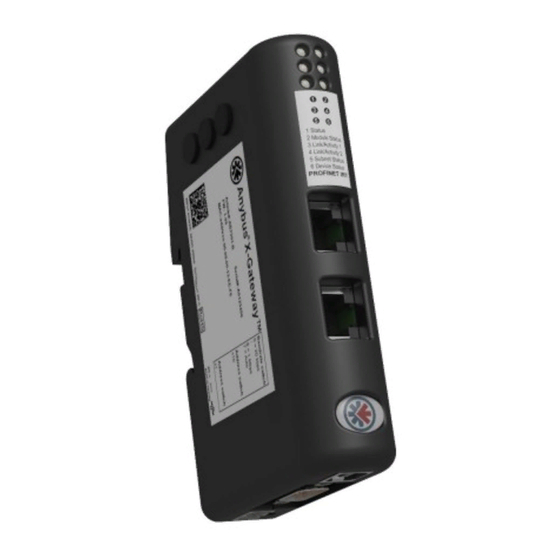
Chapter 3 3. About the Anybus X-gateway CANopen 3.1 External View A: Status LEDs See also... - “Status LEDs” on page 11 B: Fieldbus Specific Connectors and Switches This connector (connectors) and, if available, these switches are used to connect the Anybus X-gateway CANopen module to the PROFIBUS network and to configure that interface. -
Page 15: Status Leds
About the Anybus X-gateway CANopen 11 3.2 Status LEDs The status LEDs on the front indicate the status of the module as shown in the table below. Their be- havior is described in “Status LED Timing Diagrams” on page 45 Status LEDs 1 - 4 indicate the status of the PROFIBUS network and status LEDs 5 - 6 indicate the status of the CANopen subnet and the device. -
Page 16: Fieldbus Specific
About the Anybus X-gateway CANopen 12 3.3 Fieldbus Specific 3.3.1 PROFIBUS Connector Pin no Description Shield 2, 7, 9 Female B Line GND Bus + 5 V OUT A Line Casing 3.3.2 Configuration Switches The configuration switches are used to set the PROFIBUS node address. Nor- mally, these switches are covered by a plastic hatch. -
Page 17: Usb Connector
About the Anybus X-gateway CANopen 13 3.4 USB Connector At the bottom of the the module you find a USB connector used for software upgrade of the module. Pin no. Description +5 V input USBDM (USB communication signals) USBDP (USB communication signals) Signal GND Housing Cable Shield... -
Page 18: Configuration Switches
About the Anybus X-gateway CANopen 14 3.7 Configuration Switches The on-board switches on the side of the module are used to set the CANopen node address and operating baud rate. These settings cannot be changed during runtime, i.e. the gateway must be restarted in order for any changes to have effect. -
Page 19: Hardware Installation
About the Anybus X-gateway CANopen 15 3.8 Hardware Installation Perform the following steps when physically installing the gateway: 1. Snap the gateway on to the DIN-rail (See “External View” on page 10) The DIN-rail mechanism works as follows: To snap the gateway on, first press the it downwards (1) to compress the spring in the DIN-rail mechanism, then push it against the DIN-rail as to make it snap on (2) To snap the gateway off, push the it downwards (1) and pull it out from... -
Page 20: Canopen Electronic Data Sheet (Eds)
Description). This file is used by the PROFIBUS configuration tool when setting up the network. HMS provides a generic GSD file, which corresponds to the default settings in the module. This file is available for download from the HMS website, www.anybus.com, or can be obtained by contacting HMS. -
Page 21: Canopen Fieldbus Functionality
Chapter 4 4. CANopen Fieldbus Functionality The functionality of the Anybus X-gateway CANopen is defined by the CANopen DS301 Rev. 4.2 spec- ification and DSP302 (part 1-5). Note: The first time the module starts up, it starts as a slave on the CANopen network.It can be set as master during configuration, see “CANopen Configuration Example”... -
Page 22: Chapter 5 Configuration
PROFIBUS interface. 5.1 Module Identification The Anybus X-gateway CANopen to PROFIBUS module identifies itself on the network as follows: Description Value Vendor Name “HMS Industrial Networks” Model Name “X-gateway COPM” Ident Number 1836h Slave Family 9 (Gateway) Anybus X-gateway CANopen - PROFIBUS Doc.Id. - Page 23 CANopen Configuration Manager from PORT is available for download at www.anybus.com. This version of the tool can only be used for products from HMS Industrial Networks. Please contact HMS support for further information, see “Sales and Support” on page 3.
-
Page 24: Canopen Network Configuration
CANopen Configuration Manager from PORT is available for download at www.anybus.com. This version of the tool can only be used for products from HMS Industrial Networks. Please contact HMS support for further information, see “Sales and Support” on page 3. -
Page 25: Profibus Node Address Configuration
Configuration 21 There are a number of different configuration tools for PROFIBUS available on the market. The choice of tool depends on the application and the PROFIBUS master of the network. An GSD file for the ada- per interface is available at ‘www.anybus.com’. An application note, describing how to configure an Anybus PROFIBUS slave interface with Siemens STEP7, is available on the support pages for the Anybus X-gateway CANopen to PROFIBUS module at ‘www.anybus.com’. -
Page 26: Canopen Module Specification
Chapter 6 6. CANopen Module Specification 6.1 NMT State Machine The function of the Anybus X-gateway CANopen can be described as a state machine with four states. Power on Initialization Pre-operational Stopped Operational State Description Initialization When the power is switched on, the module starts initializing. The parameters are set to the so called power-on values, which are the default values or the latest stored values. -
Page 27: Data Exchange
CANopen Module Specification 23 6.2 Data Exchange The Anybus X-gateway CANopen allows for 512 bytes of data in each direction between the controlling network and the gateway. The first two bytes (the first word) are allocated for a Control/Status word, decreasing the size of I/O data for CANopen to 510 bytes. -
Page 28: Control Word
CANopen Module Specification 24 6.2.1 Control Word The control word is used to control the CANopen network of the Anybus X-gateway CANopen. It is triggered on a CoS (Change of State) event. Control Word Effective I/O Data Byte 0 Byte 1 Byte 2 - 510 Cmd, 3 bits CmdExt, 4 bits NodeID... -
Page 29: Status Word
CANopen Module Specification 25 6.2.2 Status Word Byte 0 in the status word shows the last valid command and command extension written to the control word, to indicate that the command has been performed. It also gives the lowest NodeID with error. If NodeID is 0, all nodes are fine. -
Page 30: Example
CANopen Module Specification 26 6.2.3 Example The example shows two control words from the controlling network master to the module. Each con- trol word includes a command that affects the CANopen subnetwork. Each control word is acknowl- edged by a status word, that contains a response to the command. Note that the first bit in the control word is toggled when a new command is sent, to make sure it is distinguished from the previous com- mand. -
Page 31: Pdo Functionality
CANopen Module Specification 27 6.2.4 PDO Functionality Real-time data transfer is performed by means of PDOs (Process Data Objects). The PDOs are linked to entries in the Device Object Dictionary and provide the interface to the application objects. Number and length of PDOs in a device are node specific and have to be configured by the CANopen configu- ration tool. -
Page 32: Lss Services
CANopen Module Specification 28 Transmission Mode RPDO transmission description type, RDPO 254 - 255 Event driven An RPDO is transmitted without out any relation to the SYNC object. (Default = 255) TPDO Transmission Types The TPDOs can be transmitted either in synchronous or asynchronous mode. A synchronization (SYNC) object is transmitted periodically by a synchronization master. -
Page 33: Error Control
CANopen Module Specification 29 6.4 Error Control Different mechanisms exist to monitor the network. At an error event from any of these, the active I/O data is frozen, as no new data will be available. 6.4.1 Heartbeat Mechanism The Heartbeat Mechanism is used to monitor the nodes in the network and verify that the nodes are available. -
Page 34: Static Data Types
Visible Current hardware revision hardware ver- sion string sion 100Ah Manufacturer Manufacturer software ver- Visible Set by HMS software ver- sion string sion 100Ch Guard time Used together with “Life time 0000h (default) factor” to decide the node life- time in (ms) - Page 35 Time heartbeat. Not used if 0 ms and a multiple of 1 ms 1018h Identity object Number of entries Vendor ID 1Bh (HMS Industrial Networks) Product Code 18h (Anybus X-gateway CAN- open) Revision Number Current software revision Serial Number...
-
Page 36: Configuration Manager
CANopen Supported Objects 32 Index Object Name Sub-Index Description Type Access Notes 1800h Transmit PDO Largest sub-index supported U8 parameter COB ID used by PDO 187Fh Transmission type See “TPDO Transmission Types” on page 28 Inhibit time In steps of 0.1 ms Event Timer (ms) 1A00h Transmit PDO... -
Page 37: Network Management Objects
CANopen Supported Objects 33 7.2.3 Network Management Objects The NMT master controls the states of the connected network participants, the NMT slaves. It moni- tors the devices and reports to the application, for example if an NMT slave fails. Please refer to the CANopen specification, see “Related Documents”... - Page 38 CANopen Supported Objects 34 NMT Start-up, 1F80h If a device is to be set up as NMT Master, the master functionality must be enabled in this object. It configures the start-up behavior of the device, and how it will manage the slaves. Note: The Anybus X-gateway CANopen starts up as a slave (bit 0 = 0).
- Page 39 CANopen Supported Objects 35 Slave Assignment, 1F81h This object defines which slaves the Master should monitor, control and/or configure. One entry is made for each assigned slave, with the sub-index corresponding to the slave’s Node ID. Bit No Value Description Node with this ID is not a slave Node with this ID is a slave.
- Page 40 CANopen Supported Objects 36 Request NMT, 1F82h Each node on the CANopen network can be controlled individually from the fieldbus application by sending this object. The sub-index indicates what nodes the request affects: Sub-Index Description Largest sub-index supported (128) i (with i = 1...127) Request NMT Service for the slave with Node ID i.
- Page 41 CANopen Supported Objects 37 Request Guarding, 1F83h Guarding can be initiated from the object dictionary in a similar way. Guarding is initiated with the values stored in “Slave Assignment, 1F81h” on page 35, provided that at the same time no parameters are en- tered for that node as a Heartbeat Consumer Note: This functionality is only supported in master mode.
-
Page 42: Vendor Specific Objects
CANopen Supported Objects 38 Product Code, 1F86h Each node on the CANopen network is checked against its expected product code. The sub-index in- dicates which node is checked. The node in question is only checked if data is other than zero: Sub-Index Description Largest sub-index supported (127) -
Page 43: Transmit Buffer
CANopen Supported Objects 39 7.3.1 Transmit Buffer Index Sub-index Type Access Name and Description 2000h STRUCT Transmit Byte 2-129 area Transmit Byte 2 Transmit Byte 3 Transmit Byte 129 2001h STRUCT Transmit Byte 130-257 area Transmit Byte 130 Transmit Byte 131 Transmit Byte 257 2002h STRUCT... -
Page 44: Receive Buffer
CANopen Supported Objects 40 7.3.2 Receive Buffer Index Sub-index Type Access Name and Description 2100h STRUCT Receive Byte 2-129 area Receive Byte 2 Receive Byte 3 Receive Byte 129 2101h STRUCT Receive Byte 130-257 area Receive Byte 130 Receive Byte 131 Receive Byte 257 2102h STRUCT... -
Page 45: I/O Buffer Addresses And Object Dictionary Indices Relation
CANopen Supported Objects 41 7.3.3 I/O Buffer Addresses and Object Dictionary Indices Relation The application data bytes 2 - 512 are mapped to three different areas in the Local Object Dictionary. The same data is mapped to each area, but in different data types. For example: byte to index 2000h, to 2010h, sub-index 1 - 128 and double-word (long) to index 2020h, sub-index 1 - 128. -
Page 46: General Fieldbus Parameters
CANopen Supported Objects 42 Note 2: The first two bytes are occupied by the control/status word, and are used internally by the X- gateway. These bytes should not be used for data exchange. See also “Control Word” on page 24 and “Status Word”... -
Page 47: Appendix A Technical Specification
A.1 Protective Earth (PE) Requirements The product must be connected to protective earth (PE) via the DIN-rail connector in order to achieve proper EMC behavior. HMS Industrial Networks does not guarantee proper EMC behavior unless these PE requirements are fulfilled. A.2 Power Supply Supply Voltage The gateway requires a regulated 24 V±10% DC power source. -
Page 48: Emc (Ce) Compliance
Technical Specification 44 A.4 EMC (CE) Compliance EMC compliance testing has been conducted according to the Electromagnetic Compatibility Directive 2004/108/EC. For more information please consult the EMC compliance document, see product/sup- port pages for Anybus X-gateway CANopen to PROFIBUS at www.anybus.com. Anybus X-gateway CANopen - PROFIBUS Doc.Id. -
Page 49: Appendix B Status Led Timing Diagrams
Appendix B B. Status LED Timing Diagrams The LEDs on the front of the module change their behavior according to the status of the module. This appendix gives the timing diagrams for the different indications, described in “Status LEDs” on page 11. 50 ms Flickering 50 ms... -
Page 50: Appendix C Canopen Emergency Codes
Appendix C C. CANopen Emergency Codes Below is a list of the CANopen emergency codes that can be produced by the Anybus X-gateway CAN- open. The error codes, that have been produced, can be read from the list in the Communication Profile Object at index 1003h, see 30. -
Page 51: Appendix D Canopen Configuration Example
Set Sync Interval (if used). Set Reset Timeout to the longest reset time for any node in hte network. Available for download at www.anybus.com. This version can only be used for products from HMS Industrial Networks. Anybus X-gateway CANopen - PROFIBUS Doc.Id. - Page 52 CANopen Configuration Example 48 2. Right click on group and select “Add new node” 3. Open group. Right click on the new node and select “Load EDS file”. Select the EDS file for Anybus X-gateway CANopen “EDS_X_GATEWAY_COPM_V_x_yy.eds” and press OPEN (x_yy for correct version): 4.
- Page 53 CANopen Configuration Example 49 Step 3. Input and Output Data Size To change the input size, i.e. the amount of data that is transferred out on the CANopen network from the other fieldbus, the CANopen object 3000h has to be changed and saved during CANopen configu- ration.
- Page 54 CANopen Configuration Example 50 Step 4. Add Nodes Select other nodes, configure them as CANopen slaves and save the project. Step 5. Download the Configuration When all nodes have been configured (CANopen behavior under tab “Mask”, data mapping under tab “Table”...
Need help?
Do you have a question about the Anybus X-gateway CANopen Series and is the answer not in the manual?
Questions and answers