Table of Contents
Advertisement
Quick Links
User Manual
®
Anybus
X-gateway Modbus-TCP
Modbus-TCP
Doc.Id. HMSI-168-45
Rev. 1.10
Connecting Devices
+$/067$' ‡ &+,&$*2 ‡ .$5/658+( ‡ 72.<2 ‡ %(,-,1* ‡ 0,/$12 ‡ 08/+286( ‡ &29(175< ‡ 381( ‡ &23(1+$*(1
HMS Industrial Networks
Mailing address: Box 4126, 300 04 Halmstad, Sweden
E-mail: info@hms-networks.com
Visiting address: Stationsgatan 37, Halmstad, Sweden
Web: www.anybus.com
Advertisement
Table of Contents

Subscribe to Our Youtube Channel
Related Manuals for HMS AB9008


Summary of Contents for HMS AB9008
- Page 1 Rev. 1.10 Connecting Devices +$/067$' ‡ &+,&$*2 ‡ .$5/658+( ‡ 72.<2 ‡ %(,-,1* ‡ 0,/$12 ‡ 08/+286( ‡ &29(175< ‡ 381( ‡ &23(1+$*(1 HMS Industrial Networks Mailing address: Box 4126, 300 04 Halmstad, Sweden E-mail: info@hms-networks.com Visiting address: Stationsgatan 37, Halmstad, Sweden...
- Page 2 Liability Every care has been taken in the preparation of this manual. Please inform HMS Industrial Networks AB of any inaccuracies or omissions. The data and illustrations found in this document are not binding. We, HMS Industrial Networks AB, reserve the right to modify our products in line with our policy of continuous product development.
-
Page 3: Table Of Contents
Table of Contents Table of Contents Preface About This Document ..............5 Related Documents........................5 Document History ........................5 Conventions & Terminology..................... 6 Sales and Support ........................7 Chapter 1 Getting Started ................. 8 Chapter 2 Anybus X-gateway Modbus-TCP ............ 9 Introduction .......................... - Page 4 Chapter 4 SD Card Functionality..............23 General Advice and Guidelines....................23 Starting Up..........................23 Easy Backup ..........................24 Simple Configuration Copy ..................... 24 Easy Replacement........................24 SD Card Synchronization Failure ................... 25 Chapter 5 Modbus-TCP Functions for Network 2 ......... 26 Chapter 6 Modbus-TCP Functions for Network 1 .........
-
Page 5: Preface
Preface P. About This Document For more information, documentation etc., please visit the HMS website, www.anybus.com. P.1 Related Documents Document Author Modbus Application Protocol Specification V1.1B Modbus Organization P.2 Document History Summary of Recent Changes (1.00... 1.10) Change Page(s) Updated information about data exchange to reflect the parameter data features... -
Page 6: Conventions & Terminology
About This Document P-6 P.3 Conventions & Terminology The following conventions are used throughout this manual: • Numbered lists provide sequential steps • Bulleted lists provide information, not procedural steps • The terms ‘Anybus’, ‘X-gateway’ or ‘module’ refers to the Anybus X-gateway module •... -
Page 7: Sales And Support
About This Document P-7 P.4 Sales and Support Sales Support HMS Sweden (Head Office) E-mail: sales@hms.se E-mail: support@hms-networks.com Phone: +46 (0) 35 - 17 29 56 Phone: +46 (0) 35 - 17 29 20 Fax: +46 (0) 35 - 17 29 09... -
Page 8: Chapter 1 Getting Started
Chapter 1 1. Getting Started The purpose of this chapter is to give a short description on how to install the X-gateway and get it up and running, transferring I/O data between Network 1 (the controlling network, where the X-gateway acts as a server) and Network 2 (the controlled network, where the X-gateway acts as a client). -
Page 9: Anybus X-Gateway Modbus-Tcp
Chapter 2 2. Anybus X-gateway Modbus-TCP 2.1 Introduction The Anybus X-gateway Modbus-TCP is a series of network gateways, used to provide a seamless con- nection between a Modbus-TCP network and a controlling network. This particular product connects a Modbus-TCP network to another Modbus-TCP network. In order to avoid confusion, the controlling network will be called Network 1, and the network that is controlled will be called Network 2. -
Page 10: Features
Anybus X-gateway Modbus-TCP 10 2.2 Features Anybus X-gateways for Modbus-TCP act as intelligent links between two industrial networks. On Net- work 2, they function as clients (masters) while they function as servers (slaves) on Network 1. The im- plementation is based on the Anybus NP30 ASIC technology. 2.3 Configuring the Modbus-TCP Network The Anybus X-gateway is a Modbus-TCP server (slave) on Network 1. -
Page 11: Functional Overview
Anybus X-gateway Modbus-TCP 11 2.4 Functional Overview Internally, the X-gateway consists of an intelligent gateway platform: an Anybus Modbus-TCP client in- terface for Network 2 and an Anybus Modbus-TCP server interface for Network 1. The two interfaces are interconnected through the intelligent gateway platform, which basically forwards data from one net- work to the other and vice versa as shown below. -
Page 12: Data Exchange
Anybus X-gateway Modbus-TCP 12 2.5 Data Exchange Each of the two network interfaces exchanges data on its network through two buffers. The X-gateway forwards the data between these buffers as shown below. Note that this process is separated from the network data exchange. -
Page 13: I/O Mapped Data
Anybus X-gateway Modbus-TCP 13 2.6 I/O Mapped Data I/O mapped data is cyclic data, exchanged between the networks and/or devices at a high transfer rate. It is associated with data that is continuously sent on the network. 2.7 Parameter Data Parameter data is usually exchanged acyclically, to set or change parameters in devices before or during normal process. -
Page 14: Live List
Anybus X-gateway Modbus-TCP 14 2.9 Live List The live list features the possibility for Network 1 to continuously receive an I/O mapped list containing the status of every transaction on Network 2. It is accessible using parameter access, and also I/O mapped by default. The I/O mapped live list can be enabled/disabled when configuring the Network 1 settings. -
Page 15: Transaction Status List
Anybus X-gateway Modbus-TCP 15 2.10 Transaction Status List This list holds information about the transactions between Network 2 and the module, from the per- spective of the module. It is a list available from the module, which is possible to be retrieved acyclically (using parameter access) by the Modbus-TCP network. -
Page 16: Exception Code List
Anybus X-gateway Modbus-TCP 16 2.11 Exception Code List If Modbus transactions fail, the slaves can respond with an exception code. These can be found in the exception code list available from the module, possible to be retrieved acyclically (using parameter ac- cess) by the Modbus-TCP network. -
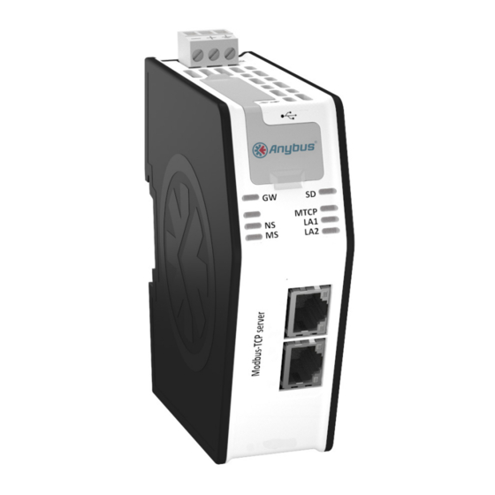
Page 17: About The Anybus X-Gateway Modbus-Tcp
Chapter 3 3. About the Anybus X-gateway Modbus-TCP 3.1 External View • A: Power Connector This connector is used to apply power to the X- gateway. It is also possible to connect protective earth (PE) to the power connector. See “Power Connector”... -
Page 18: Mounting The X-Gateway
About the Anybus X-gateway Modbus-TCP 18 3.2 Mounting the X-gateway The Anybus X-gateway can be physically installed either by mounting it onto a DIN-rail or, if installed in areas exposed to vibration, by mounting it on a wall for more stability. 3.2.1 DIN-rail Mounting Make sure the DIN-rail fastening mechanism on the back of the module is in a fixed and closed position, i. -
Page 19: Wall Mounting
About the Anybus X-gateway Modbus-TCP 19 3.2.2 Wall Mounting Use the wall mounting option if there is a need to place the X-gateway in an environment exposed to vibration. This way of mounting the module offers more stability than the traditional DIN-rail mount- ing. -
Page 20: Status Leds
About the Anybus X-gateway Modbus-TCP 20 3.3 Status LEDs Note: A test sequence is performed on all LEDs during startup. Note: An identification LED sequence can be performed on LEDs 1, 5 and 6 by clicking the “Wink device” button in the X-gateway Management section in the web configuration interface. X-gateway and Network 2 LEDs LED no State... -
Page 21: Usb Connector
About the Anybus X-gateway Modbus-TCP 21 3.4 USB Connector At the upper front of the module there is a USB connector used for firmware upgrades. Pin no. Description +5V Input USBDM (USB communication signals) USBDP (USB communication signals) Signal GND Housing Cable Shield 3.5 Modbus-TCP Connectors (Network 1) -
Page 22: Power Connector
About the Anybus X-gateway Modbus-TCP 22 3.7 Power Connector Pin no. Description +24V DC PE (Protective Earth) 1 2 3 Notes: • Use 60/75 or 75×C copper (CU) wire only. • The terminal tightening torque must be between 5... 7 lbs-in (0.5... 0.8 Nm) See also... -
Page 23: Sd Card Functionality
Chapter 4 4. SD Card Functionality Using an SD card with the X-gateway adds the following features: • Easy backup. Every applied change in the configuration will automatically be saved to the X-gateway and the SD card. See “Easy Backup” on page 24. •... -
Page 24: Easy Backup
SD Card Functionality 24 4.3 Easy Backup Every time a configuration change is applied in the X-gateway Management section using the configu- ration web pages, the configuration is saved both in the memory of the X-gateway and on the SD card. This is the easiest way of keeping a continuously updated configuration backup. -
Page 25: Sd Card Synchronization Failure
SD Card Functionality 25 4.6 SD Card Synchronization Failure In the event of applying a configuration or restoring a configuration from a backup file, the SD card synchronization can fail. There are many possible reasons for an SD card write failure: •... -
Page 26: Modbus-Tcp Functions For Network 2
Chapter 5 5. Modbus-TCP Functions for Network 2 This chapter will present information about the Modbus-TCP functions that are supported on Network 2 (where the X-gateway acts as a master). The Modbus-TCP protocol is an implementation of the standard Modbus protocol, running on top of TCP/IP. -
Page 27: Modbus-Tcp Functions For Network 1
Chapter 6 6. Modbus-TCP Functions for Network 1 The X-gateway supports the following Modbus-TCP functions for Network 1: Function Input Ranges Output Ranges Read Coils 0000h - 0FFFh (coils) Read Discrete Inputs 0000h - 0FFFh (coils) Read Holding Registers 0100h - 01FFh (registers) 0000h - 00FFh (registers) Read Input Registers 0000h - 00FFh (registers) -
Page 28: Chapter 7 Network Configuration
Chapter 7 7. Network Configuration 7.1 General Information The Anybus X-gateway features built-in web pages for easy configuration. The web pages are all de- scribed in this chapter. To access the web configuration pages, the following system requirements need to be met: •... -
Page 29: Introduction
Network Configuration 29 7.2 Introduction To display the configuration and status web pages of the X-gateway, start a web browser and type the IP address of the module in the address field. The default IP address of the X-gateway is 192.168.0.100. To connect a computer to the X-gateway, make sure that both the computer and the module are using the same subnet mask, e.g. -
Page 30: Overview
Network Configuration 30 7.3 Overview The configuration and status web pages are divided into three sections: 1. Headline Section Shows the Anybus logo and the name of the product. 2. Navigation Section All functionality is easily accessed from the different links. Every link and its corresponding func- tionality will be explained later in this chapter. -
Page 31: Home
Network Configuration 31 7.3.1 Home The introductory window of the configuration and status web pages presents important error tracking information, as well as general information and statistics. Operation Mode The table below shows the correlation between the operation modes of Network 1 and Network 2. Modbus-TCP (Network 1) I/O data exchanged No I/O data exchanged... -
Page 32: Configuration
Network Configuration 32 7.4 Configuration Please note that changes made to the configuration will not be used by the X-gateway until they have been applied and saved. See “X-gateway Management” on page 39. 7.4.1 Authentication Authentication can be enabled or disabled. If enabled, it is possible to set a username and password to protect the configuration. -
Page 33: Modbus Client (Network 2)
Network Configuration 33 7.4.2 Modbus Client (Network 2) Configuration of the client side of Network 2. On this side, the X-gateway will act as a Modbus-TCP client. To the right, in the “Actual” column, the currently used values can be seen. Available IP Configuration Settings Item Description... -
Page 34: Modbus Servers
Network Configuration 34 7.4.3 Modbus Servers The configuration of the servers on the Modbus-TCP network is made here. The X-gateway can handle up to 64 different servers, and a maximum of 64 transactions distributed among those servers. It is pos- sible to map up to 256 bytes of data in either direction, including control/status word and live list. - Page 35 Network Configuration 35 Add Transactions Transactions represent the data that is read from/written to the servers of the Modbus-TCP network. The global configuration limits box keeps track of the number of added transactions, the current mini- mum allowed scan time, and the current amount of I/O mapped data as well at the total amount of data (both I/O mapped and not I/O mapped data).
- Page 36 Network Configuration 36 Available settings Setting Description Function code The function code defines the purpose of the transaction. Choose from five different Modbus functions, see “Modbus-TCP Functions” on page 26. Data encoding Decides in what order the different bytes of the received/transmitted data shall be sent on the net- work.
-
Page 37: Modbus-Tcp (Network 1 Server Interface)
Network Configuration 37 7.4.4 Modbus-TCP (Network 1 Server Interface) Configuration of the Modbus-TCP server interface of the X-gateway. What is shown is the currently stored configuration, provided that all changes are saved and applied to the X-gateway. The column ‘Actual’ presents the settings that are currently used. The TCP/IP settings (IP address, Sub- net mask and Gateway) can be changed by the Modbus-TCP network (Network 1) during runtime and will then override the chosen values in the configuration web pages. - Page 38 Network Configuration 38 Available settings for the Modbus-TCP network Setting Description IP address If not set by Network 1 or DHCP, set these values manually. (Disable DHCP to make the fields editable). Subnet mask Gateway DHCP Enabled by default. When enabled, the X-gateway can obtain the TCP/IP settings dynamically from the DHCP server of the Modbus-TCP network (Network 1).
-
Page 39: Tools
Network Configuration 39 7.5 Tools 7.5.1 X-gateway Management Apply changes Permanently store changes made to the configuration and reboot, using the new configuration. No changes made in the configuration will be permanently stored or used by the X-gateway until they are applied by clicking ‘Apply’. -
Page 40: Mapping Overview
Network Configuration 40 7.5.3 Mapping Overview This page provides a description of all data resulting from the transactions of the currently applied con- figuration. It is divided into two parts. The first part describes the X-gateway interface to Network 1, and the second part all applied transactions on Network 2. - Page 41 Network Configuration 41 Mapping Overview Example Anybus X-gateway Modbus-TCP Doc.Id. HMSI-168-45 Doc.Rev. 1.10...
-
Page 42: Transaction Monitor
Network Configuration 42 7.5.5 Transaction Monitor The transaction monitor interface presents a detailed list of all transaction units currently operating on the Modbus-TCP network. The data is automatically updated, and it is possible to choose to view the data either in decimal or in hexadecimal values. The time that has passed since the last update is visible at the top of the transaction list. -
Page 43: Appendix A Technical Specification
In order to achieve proper EMC behavior, the product must be connected to protective earth (PE) via the DIN-rail connector. If the DIN-rail cannot be used, PE must be connected to the power connector. HMS Industrial Networks does not guarantee proper EMC behavior unless these PE requirements are fulfilled. -
Page 44: Emc (Ce) Compliance
Technical Specification 44 A.4 EMC (CE) Compliance EMC compliance testing has been conducted according to the Electromagnetic Compatibility Directive 2004/108/EC. For more information please consult the EMC compliance document, see product/sup- port pages for Anybus X-gateway Modbus-TCP at www.anybus.com. Anybus X-gateway Modbus-TCP Doc.Id. -
Page 45: Appendix B Anybus Ipconfig Tool
Appendix B B. Anybus IPconfig Tool The X-gateway supports the HICP protocol used by the Anybus IPconfig tool and all Anybus products. It is possible to see and alter the TCP/IP set- tings for the X-gateway manually by using the IPconfig Tool. -
Page 46: Appendix C Copyright Notices
Appendix C C. Copyright Notices This product includes software developed by Carnegie Mellon, the Massachusetts Institute of Technology, the Uni- versity of California, and RSA Data Security: ***************************************************************************** Copyright 1986 by Carnegie Mellon. ***************************************************************************** Copyright 1983,1984,1985 by the Massachusetts Institute of Technology ***************************************************************************** Copyright (c) 1988 Stephen Deering.
Need help?
Do you have a question about the AB9008 and is the answer not in the manual?
Questions and answers