Table of Contents
Advertisement
Quick Links
HMS Industrial Networks AB
Germany
+ 49 - 721 - 96472 - 0
Japan
+ 81 - 45 - 478 -5340
Sweden
+ 46 - 35 - 17 29 20
U.S.A
+ 1
- 773 - 404 - 3486
Anybus
PROFINET/USS Gateway
ge-sales@hms-networks.com
jp-sales@hms-networks.com
sales@hms-networks.com
us-sales@hms-networks.com
User Manual
Communicator
®
™
Rev. 1.01
Advertisement
Table of Contents

Related Manuals for HMS Anybus Communicator PROFINET-USS


Summary of Contents for HMS Anybus Communicator PROFINET-USS
- Page 1 User Manual Anybus Communicator ® ™ PROFINET/USS Gateway Rev. 1.01 HMS Industrial Networks AB Germany + 49 - 721 - 96472 - 0 ge-sales@hms-networks.com Japan + 81 - 45 - 478 -5340 jp-sales@hms-networks.com Sweden + 46 - 35 - 17 29 20 sales@hms-networks.com...
-
Page 3: Table Of Contents
Table of Contents Table of Contents Preface About This Document How To Use This Document ......................P-1 Important User Information ......................P-1 Related Documents..........................P-2 Document History ..........................P-2 Conventions & Terminology......................P-3 Support ..............................P-3 Chapter 1 Introduction General Information..........................1-1 Features..............................1-1 External View ............................1-2 Status LEDs ............................1-3... - Page 4 Chapter 4 Web Interface General Information..........................4-1 Administration Pages..........................4-2 General Information........................4-2 IP Address Settings ........................4-2 Master Communication Settings ....................4-3 Master Configuration ........................4-3 E-Mail Notification Settings......................4-4 Slave Diagnostics...........................4-5 General............................4-5 Identification and Status ....................... 4-5 Slave Status..........................4-6 View Process Data of Operational Slaves..................
-
Page 5: Preface
Windows operating system. Important User Information The data and illustrations found in this document are not binding. We, HMS Industrial Networks AB, reserve the right to modify our products in line with our policy of continuous product development. The information in this document is subject to change without notice and should not be considered as a com- mitment by HMS Industrial Networks AB. -
Page 6: Related Documents
About This Document P-2 Related Documents Document Author Document History Summary of Recent Changes (1.00... 1.01) Change Page(s) Removed redundant section ‘Gateway Status Register’ Misc. minor corrections and adjustments Revision List Revision Date Author Chapter(s) Description 1.00 2006-09-05 Initial revision 1.01 2007-08-27 Misc. -
Page 7: Conventions & Terminology
‘Slave Data Set’ refers to all data associated with a slave. • Hexadecimal values are written in the format 0xNNNN, where NNNN is the hexadecimal value. Support HMS Sweden (Head Office) E-mail: support@hms-networks.com Phone: +46 (0) 35 - 17 29 20... -
Page 8: Chapter 1 Introduction
Chapter 1 Introduction General Information The Anybus Communicator Ethernet-USS Gateway functions as a gateway between the Universal Serial Interface Protocol (from now on referred to as ‘USS’) and PROFINET IO. Acting as a slave with Real Time capabilities on the PROFINET side, and as a master on the USS network, it controls up to 31 USS slaves. -
Page 9: External View
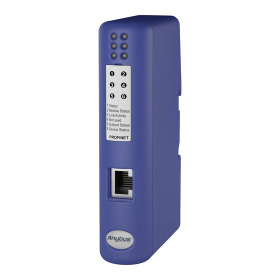
Introduction 1-2 External View (See also B-1 “Connector Pin Assignments”). A: PROFINET Interface See also... - B-1 “PROFINET Interface (RJ45)” B: Status LEDs See also... - 1-3 “Status LEDs” C: Service Port (reserved) D: USS Interface See also... - B-1 “USS Interface (DB9F)” E: Power Supply Input See also... -
Page 10: Status Leds
Introduction 1-3 Status LEDs State Status 1 - Comm. Status Off line - No connection with IO Controller Green On line, RUN - Connection to IO Controller established - IO Controller is in RUN state Green, flashing On line, STOP - Connection to IO Controller established - IO Controller in STOP state 2 - Module Status... -
Page 11: Data Exchange
Chapter 2 Data Exchange Overview The mapping of USS data to PROFINET is based on the mapping scheme defined by the PNO working group for PROFINET IO Proxy Devices. In short, this means that on PROFINET, each USS slave is represented through a dedicated slot. -
Page 12: Uss Master Implementation
Data Exchange 2-2 USS Master Implementation General Information The USS protocol (Universal Serial Interface Protocol), defines an access technique according to the Master-Slave principle for communication via a serial RS-485 based communication bus. The protocol includes fixed- or variable frame length, cyclic, acyclic and point-to-point communications. The gateway communicates according to a subset of the protocol, implementing support for cyclic communication with fixed frame lengths. -
Page 13: Slave Data Set
Data Exchange 2-3 Slave Data Set General Information The data associated with each slave is organized as follows: Data from Gateway Data from IO Controller Slave Status Register (reserved, set to zero) (2 bytes) Parameter Data (PKW) Parameter Data (PKW) (size is device dependent) Process Data (PZD) Process Data (PZD) -
Page 14: Network Configuration
As mentioned previously, the gateway can be configured solely via the PROFINET configuration tool (e.g. Step 7). No local configuration utilities or settings are required. The configuration is based on the PROFINET GSD-file, which can be downloaded from the HMS web site (‘www.anybus.com’). TCP/IP Settings To participate on the PROFINET network, the gateway needs a valid TCP/IP configuration. -
Page 15: Station Name
Network Configuration 3-2 Station Name General Information When used for the first time, the gateway needs to be assigned a Station Name. This can either be done using the SIMATIC Manager or using the SIMATIC Primary Setup Tool. Both cases are described in this document. -
Page 16: Simatic Manager (Edit Ethernet Node)
Network Configuration 3-3 SIMATIC Manager (Edit Ethernet Node) Note: The following example uses the SIMATIC Manager. It is also possible to use the SIMATIC Pri- mary Setup Tool, see 3-2 “SIMATIC Primary Setup Tool” To specify the Station Name using the SIMATIC Manager, perform the following steps. 1. -
Page 17: Uss & Profinet Configuration (Simatic Manager)
Network Configuration 3-4 USS & PROFINET Configuration (SIMATIC Manager) General Information The purpose of this section is to illustrate how to add the gateway and data from the USS slaves to the PROFINET configuration. Note that a prerequisite for the following examples is that all TCP/IP set- tings are properly configured. -
Page 18: Step 2: Specify The Baudrate For The Uss Network
Network Configuration 3-5 Step 2: Specify the Baudrate for the USS Network To specify the baudrate for the USS communication, perform the following steps: 1. Highlight the gateway in the network configuration (‘HW Config’-window, ‘A’) 2. Right-click on slot #0 (‘B’) and select ‘Object Properties’. 3. -
Page 19: Step 3: Add Data From The Uss Network To The Configuration
Network Configuration 3-6 Step 3: Add Data from the USS Network to the Configuration Each slave on the USS network is represented trough a dedicated slot. The slot number correlates 1:1 to the USS slave number, i.e. slot #23 on PROFINET represents USS slave #23. To add data from the USS network to the configuration, perform the following steps: 1. -
Page 20: Web Interface
- 4-2 “Administration Pages” • Slave Diagnostics See also... - 4-5 “Slave Diagnostics” • User defined pages (Expert Users Only) Optionally, advanced users may create custom web pages. Contact HMS for further information. Note: Certain features requires a JAVA-capable browser. -
Page 21: Administration Pages
Web Interface 4-2 Administration Pages General Information The main administration page features the following sub-pages: • IP address settings See also... - 4-2 “IP Address Settings” • Master Communication Settings See also... - 4-3 “Master Communication Settings” • Master Configuration See also... -
Page 22: Master Communication Settings
Web Interface 4-3 Master Communication Settings This page presents the communication settings for the USS interface. • Baudrate The following baudrates are supported: - 9600bps - 19200bps - 38400bps (Note that the baudrate is specified in the PROFINET configuration tool, see 3-5 “Step 2: Specify the Baudrate for the USS Network”) •... -
Page 23: E-Mail Notification Settings
Web Interface 4-4 E-Mail Notification Settings The gateway continuously monitors the status of OP, USSF and FNF in the Slave Status Registers. Op- tionally, an email notification can be issued when the status of a slave changes. • Recipient Destination address. •... -
Page 24: Slave Diagnostics
- 4-6 “View Process Data of Operational Slaves” Identification and Status This page displays information about the gateway as well as the general status of the USS network (this information may be useful when contacting HMS support services). • Gateway Name (‘Profinet Gateway for Siemens Drives with USS Protocol ’). -
Page 25: Slave Status
Web Interface 4-6 Slave Status This page shows status information for each slave device on the USS network. • Device address. • Operational Device status (e.g. ‘Operational’, ‘Non-Opera- tional’, ‘Not Present’ etc.). • PKW Size Size (in words) of Parameter Data (PKW) as- sociated with the slave device. -
Page 26: Appendix A Anybus Ipconfig (Hicp)
The gateway supports the HICP protocol used by the Anybus IPconfig utility, which can be downloaded free of charge from the HMS web site. This utility may be used to access the TCP/IP settings of any Anybus product connected to the network via UDP port 3250. -
Page 27: Appendix B Connector Pin Assignments
Appendix B Connector Pin Assignments PROFINET Interface (RJ45) Signal Notes Normally left unused; to ensure signal integrity, these pins are tied together and terminated to PE via a filter circuit. Normally left unused; to ensure signal integrity, these pins are tied together and terminated to PE via a filter circuit. -
Page 28: Appendix C Technical Specification
Appendix C Technical Specification Mechanical Properties Housing Plastic housing with snap-on connection to DIN-rail, protection class IP20 Dimensions 120 mm x 75 mm x 27 mm, L x W x H (inches: 4,72” x 2,95” x 1,06”; L x W x H) Electrical Characteristics Power Supply Power: 24V ±... -
Page 29: Regulatory Compliance
Technical Specification C-2 Regulatory Compliance EMC Compliance (CE) This product is in accordance with the EMC directive 89/336/EEC, with amendments 92/31/EEC and 93/68/EEC through conformance with the following standards: • EN 50082-2 (1993) EN 55011 (1990) Class A • EN 61000-6-2 (1999) EN 61000-4-3 (1996) 10V/m EN 61000-4-6 (1996) 10V/m (all ports) EN 61000-4-2 (1995) ±8kV...
Need help?
Do you have a question about the Anybus Communicator PROFINET-USS and is the answer not in the manual?
Questions and answers