Table of Contents

Related Manuals for HMS Anybus-X


Summary of Contents for HMS Anybus-X
- Page 1 Anybus-X Ethernet to J1939 Gateway User Manual Part No. AB7665 Rev 1.00 HMS Industrial Networks Pilefeltsgatan 93-95 SE-302 50 Halmstad Sweden Phone +46 (0) 35 17 29 00 Web www.anybus.com © 2005 HMS Industrial Networks. AB7665 User Manual...
-
Page 2: Table Of Contents
Preface................. iv About This Manual ..........iv Important User Information ........iv Related Documentation........... v Document Revision..........v Anybus-X Module Description ....... 1-1 Overview ..............1-1 Theory of Operation ........... 1-2 J1939 Features ............1-3 Ethernet Features ............1-3 System Requirements ..........1-4 Hardware Description.......... - Page 3 Ethernet Network Configuration ......... 7-7 J1939 Network Configuration ........7-7 J1939 I/O Configuration ..........7-8 Status and Diagnostics..........8-1 Anybus-X LEDs ............8-1 J1939 Status Codes ........... 8-4 Diagnostic Web Pages ..........8-5 Status Assembly ............8-5 Specifications ............9-1 Environmental Specifications ........
- Page 4 Connectors .............. 10-1 Power ............... 10-1 J1939 ............... 10-2 Ethernet RJ45 ............10-3 Configuration RS-232 9 Pin D-Subminiature.... 10-4 Warranty ..............11-1 Support ..............12-1 Technical Product Assistance ........12-1 Contact Information ..........12-1 © 2005 HMS Industrial Networks. AB7665 User Manual...
-
Page 5: Preface
Preface iv Preface About This Manual This manual discusses the use of the Anybus-X Ethernet to J1939 Gateway. It describes how to install, configure, and operate the module. Important User Information The data and illustrations found in this document are not binding. We reserve the right to modify our products in line with our policy of product development. -
Page 6: Related Documentation
Modbus Messaging on TCP/IP Implementation Modbus-IDA www.modbus.org Guide J1939 Recommended Practice www.sae.org Table 1-1 Related Documentation Document Revision Date Revision Change Description 7/15/2005 1.00 Initial Release Table 1-2 Document Revision Log © 2005 HMS Industrial Networks AB7665 User manual... -
Page 7: Anybus-X Module Description
Anybus-X Module Description Overview The Anybus-X Ethernet to J1939 Gateway allows you to monitor and control data on a J1939 heavy duty vehicle network from an Ethernet device. Data from J1939 messages are mapped to I/O table locations, making them accessible to the Ether- net network. -
Page 8: Theory Of Operation
Table Figure 1-1 Anybus-X PassageWay Operation The Anybus-X appears as a single device on either network using standard proto- col mechanisms. No special, or extended, protocol features are required of the devices on either network to read and write the data flowing through the Passage- Way;... -
Page 9: J1939 Features
Supports the Modbus/TCP protocol with up to 8 simultaneous connec- tions. Conforms to the Modbus/TCP specification 1.0. • IP address configuration may be done using DHCP/Bootp, web page, or the Anybus-X Configuration Tool. © 2005 HMS Industrial Networks AB7665 User manual... -
Page 10: System Requirements
Optional Hardware • DIN rail to mount the Anybus-X. Required Software • Anybus-X Configuration Tool software (BWConfig) to configure the Anybus-X. • BWConfig requires that the PC be running Microsoft Windows 95, 98, NT, 2000, or XP. © 2005 HMS Industrial Networks... -
Page 11: Hardware Description
See “Ethernet Network Configuration” Page 3-6 for more details on con- figuring the IP address using the switches. On the front of the Anybus-X module are 6 LEDs that are used for status indica- tion. These LEDs provide visual status for the overall module, the J1939 interface, and the Ethernet interface. -
Page 12: Installation
•Terminal tightening torque must be between 5-7 lbs-in (0.5-0.8 Nm). •For use in Class 2 circuits only. •Suitable for surrounding temperature of 65 degrees C maximum. •Use 60/75 C copper wire only. © 2005 HMS Industrial Networks AB7665 User manual... -
Page 13: Power And Network Connections
Installation 2-2 Power and Network Connections The power and network connections to the Anybus-X are made on the end of the module. Figure 2-1 indicates the location of each connector. J1939 Power Configuration Ethernet Ethernet IP Address Figure 2-1 Anybus-X Power and Network Connections ©... -
Page 14: Connecting Power
24VDC Common 24 VDC + Figure 2-2 Power Connection The Anybus-X requires 24 volts DC power. The module will start immediately when power is applied (There is no On/Off switch on the module). © 2005 HMS Industrial Networks AB7665 User manual... -
Page 15: Connecting J1939
The J1939 network connection is a 5-pin terminal block located next to the power connection on the end of the module. The female terminal block connector is pro- vided with the Anybus-X. Connections to be made are illustrated in Figure 2-3. 24VDC +... -
Page 16: Connecting To Ethernet
(3) Transmit Data Figure 2-4 Configuration Port Connector The Anybus-X is connected to a PC for configuration using a null-modem cable. A null-modem cable has pins 2 and 3 swapped so that the PC’s Transmit line is connected to the Anybus-X’s Receive line, and the PC’s Receive line is connected to the Anybus-X’s Transmit line. -
Page 17: Configuration
Chapter 3 Configuration 3-1 Configuration This chapter describes how the Anybus-X Ethernet to J1939 Gateway is config- ured using the Anybus-X Configuration Tool (BWConfig). Detailed descriptions of each configurable parameter in the gateway are provided as well as how they are set in the tool. - Page 18 Launch BWConfig from the Anybus-X Configuration folder in the Windows Start Menu. When BWConfig is started, it will attempt to locate a Anybus-X module on one of the PC serial ports. If a module is found, the status area of the tool will be updated to show the module type and status of the module that was located.
- Page 19 Configuration 3-3 BWConfig User Interface The Anybus-X Configuration Tool’s user interface is shown in Figure 3-1. Figure 3-1 BWConfig User Interface © 2005 HMS Industrial Networks AB7665 User manual...
- Page 20 Configuration of the content and layout of the I/O tables. Tool Operations The following operations are available through the BWConfig menus and tool bar. New File Create a new Anybus-X configuration for the selected type of module. Open File Open a previously saved Anybus-X configura- tion.
- Page 21 Remove I/O Point Delete the selected input or output data point from the J1939 I/O configuration. Flash Update Perform a field upgrade of the Anybus-X module’s firmware. Note: Care should be taken when upgrading firmware, an incomplete update could cause irreparable harm to the module.
-
Page 22: Ethernet Network Configuration
The duplex setting that the module will use to Half, Full, or communicate on the Ethernet network. Auto If the network duplex is set to Auto, the mod- ule will auto-negotiate duplex. Table 3-1 Ethernet Network Configuration Parameters © 2005 HMS Industrial Networks AB7665 User manual... - Page 23 Ethernet network. If the option is enabled, and no Modbus requests are received within the configured timeout period, the module Run/Idle status will be set to Idle. Table 3-1 Ethernet Network Configuration Parameters © 2005 HMS Industrial Networks AB7665 User manual...
-
Page 24: J1939 Network Configuration
Configuration 3-8 J1939 Network Configuration The J1939 network configuration contains the parameters used by the Anybus-X for J1939 address management and other network interface options. The parame- ters are described in Table 3-2 below. Refer to Figure 3-1 to see how each param- eter is displayed on the user interface. - Page 25 Each component of the NAME value is broken out and displayed in the lower fields of the dialog; components can be edited individually using these fields. Pressing the Apply button will update either set of fields to reflect the changes that were made. © 2005 HMS Industrial Networks AB7665 User manual...
-
Page 26: J1939 I/O Configuration
Figure 3-3. Note that both Input and Output data points have the same parameters with the exception of the message priority; only the out- put data points have configurable message priority. Figure 3-3 J1939 Data Point Configuration © 2005 HMS Industrial Networks AB7665 User manual... - Page 27 Figure 3-4 J1939 Data Point Editing Dialog The parameters associated with I/O data points are described in Table 3-3. © 2005 HMS Industrial Networks AB7665 User manual...
- Page 28 Input table. If this is an output data point, a message with this PGN will be built and transmitted using data from the Output table. Table 3-3 J1939 I/O Data Point Parameters © 2005 HMS Industrial Networks AB7665 User manual...
- Page 29 Target Address. The message will be broadcast if the Target Address is set to 255. Table 3-3 J1939 I/O Data Point Parameters (Continued) © 2005 HMS Industrial Networks AB7665 User manual...
- Page 30 2 values separated by a comma or a period will be interpreted as a byte, bit combination. i.e. ‘16’ and ‘2,0’ are equivalent entries. Table 3-3 J1939 I/O Data Point Parameters (Continued) © 2005 HMS Industrial Networks AB7665 User manual...
- Page 31 Configuration 3-15 J1939 Diagnostic Tables The Anybus-X has the ability to monitor the commonly used diagnostic messages on J1939. The Active Diagnostics (DM1) and Previously Active Diagnostics (DM2) can be monitored by the Anybus-X. Configuring diagnostic tables is done through the input data points in much the same manner as data PGN configura- tion.
- Page 32 This will automatically be set to 0 Table 3-4 Input Data Point Parameters for Diagnostic Tables Note: See “J1939 Diagnostic Messages” on page 6-8 for details of the format of the diagnostic tables in the input data table. © 2005 HMS Industrial Networks AB7665 User manual...
-
Page 33: Ethernet Network Configuration
This is a private address and can only be used on a local intranet. In such a case a Web Browser such as Microsoft’s Internet Explorer can be used to access the Anybus-X’s web page which allows changing the IP Address, Subnet mask, and GateWay address settings. - Page 34 Subnet mask, and Gateway address is automatically configured by the DHCP/BootP server. It can be enabled using the Anybus-X’s Settings web page. Note: The use of DHCP is the default configuration for the Anybus-X as shipped. © 2005 HMS Industrial Networks...
- Page 35 Setting the IP Address Using the Web Page The ethernet addresses can also be configured using the Status and Settings web page resident on the Anybus-X. The Status and Settings web page appears as shown below. Figure 3-7 Status and Settings Web Page ©...
- Page 36 The IP address, subnet mask, and default gateway address are displayed in the edit boxes on the web page. Changing any values and clicking the Submit Values but- ton will set the addresses in the Anybus-X. Note that a power cycle or module reset is required for the changes to take effect.
- Page 37 Configuration 3-21 IP Address Initialization The following flowchart describes how the IP configuration is determined when the Anybus-X is powered up. Start Valid Configuration DIP Switch = 0 File? Request config from DHCP/ DHCP BOOTP Server. Enabled? Timeout 30 secs...
-
Page 38: Ethernet/Ip Interface
As an I/O Server it can respond to requests for I/O messages but it does not gener- ate such requests. A Scanner device would generate these requests. The Anybus-X supports Message Server functionality. This means it can act as a target message requests. -
Page 39: I/O Messaging
EtherNet/IP 4-2 I/O Messaging The Anybus-X allows an EtherNet/IP Scanner access to the I/O data tables. The data received from the J1939 network is collected in the Input Table (IN) of the Anybus-X and becomes the EtherNet/IP Input data to the EtherNet/IP scanner. -
Page 40: Assembly Objects And Connections
I/O assemblies. (see the assembly formats below) If a connection is created with a size larger than the configured I/O data table size, the extra data will be filled with 0. © 2005 HMS Industrial Networks AB7665 User manual... - Page 41 0. The status register is a bit string with the following bit definitions. Description Anybus-X is in Run mode. (Cleared if in Idle mode.) Anybus-X is online on the J1939 network. J1939 network interface fault. 3-31 Not used.
- Page 42 System Run Mode. Used in conjunction with the Local Run Mode bit in the Command register to determine the run mode of the Anybus-X. Both bits must be set for the Anybus-X to be in Run mode; oth- erwise the module will be in Idle mode. 1-31 Not used.
- Page 43 Run Mode bit in the Command register to deter- mine the run mode of the Anybus-X. Both bits must be set for the Anybus-X to be in Run mode; otherwise the module will be in Idle mode. Reset Faults. Resets the J1939 network interface faults.
- Page 44 EtherNet/IP 4-7 Status Assembly The status assembly is a collection of status and diagnostic information for the Anybus-X J1939 interface. The information in the assembly is updated once a second. Byte Size Data Type Name Description Offset in Bytes UINT...
- Page 45 J1939 Transmit Queue Overflow. The J1939 transmit queue has overflowed. This is a sticky bit; it will not be cleared until a Clear Fault command has been issued. 7-15 Not used. Table 4-9 J1939 Fault Register Bit Definitions © 2005 HMS Industrial Networks AB7665 User manual...
-
Page 46: Using Controllogix With The Gateway
Using ControlLogix with the Gateway When configuring I/O connections between a Rockwell Automation Control- Logix EtherNet/IP scanner and the Anybus-X, the Generic EtherNet/IP device type should be used. Figure 4-2 shows an example RSLogix configuration for an Ethernet to J1939 Gateway module. Note that the sizes for Input and Output should be set based on the bytes allocated in the I/O tables in the J1939 I/O con- figuration done with BWConfig. - Page 47 Run/Idle header that is automatically added by the controller. The maximum connection size that ControlLogix allows is 500 bytes. Hence the total 508 bytes of the input and output areas cannot be accessed when using Con- trolLogix. © 2005 HMS Industrial Networks AB7665 User manual...
-
Page 48: Modbus/Tcp Interface
Chapter 5 Modbus/TCP 5-1 Modbus/TCP Interface The Anybus-X supports Modbus/TCP commands. The implementation of the Modbus/TCP server is done according to the Modbus/TCP specification 1.0. All commands according to class 0 and class 1 are implemented and a subset of the class 2 commands. -
Page 49: Supported Exception Codes
Modbus/TCP 5-2 Supported Exception Codes An exception code is returned in the response when the Anybus-X is unable to service the Modbus request that was received. The following exception codes will be used by the Anybus-X. Exception Name Description Code... -
Page 50: Modbus/Tcp Addressing
Modbus/TCP 5-3 Modbus/TCP Addressing The Anybus-X’s Input (IN) and Output (OUT) areas are set to a maximum size of 508 bytes each. The Status assembly area is 10 bytes. When accessing these areas, with Modbus commands, the addressing is done according to the following tables. -
Page 51: I/O Data Content
The content of the input and output data is the same as the content of the I/O assemblies used in EtherNet/IP (See section “Input Assembly” on page 4-4, sec- tion “Output Assembly” on page 4-5, and section “Status Assembly” on page 4- © 2005 HMS Industrial Networks AB7665 User manual... -
Page 52: I/O Data Format
Modbus/TCP 5-5 I/O Data Format The Anybus-X transfers I/O data between Modbus/TCP and J1939 without regard to data content or format. Due to this, the user is responsible for making sure that the devices on either network understand the format of the data. -
Page 53: J1939 Interface
J1939 network using that address. If an address cannot be claimed, the module moves to the next address in the list and attempts to claim that address. If no addresses in the list can be claimed, the module remains offline. © 2005 HMS Industrial Networks AB7665 User manual... -
Page 54: Communications Methods
Communications Methods The J1939 network interface supports reception and transmission of the following J1939 message types in accordance to the J1939-21 specification. •PDU1 destination specific •PDU1 broadcast •PDU2 (broadcast) © 2005 HMS Industrial Networks AB7665 User manual... -
Page 55: Message Transmission
Automatic transmission for a message will occur Update Time milliseconds after the last transmission of the message, regardless of whether the last transmission was automatic or a response to a request PGN. © 2005 HMS Industrial Networks AB7665 User manual... - Page 56 • If the transmission is due to a request and the request was broadcast, the message will be broadcast. © 2005 HMS Industrial Networks AB7665 User manual...
-
Page 57: Receiving Messages
Input table according to the data point configura- tion. Data of the configured length is copied from the configured message buffer offset to the configured Input table offset. © 2005 HMS Industrial Networks AB7665 User manual... - Page 58 1. This will effect all input data points associated with the PGN/Target Address. The operation is as if a message was received which contained 0xFF for all data bytes in the message. © 2005 HMS Industrial Networks AB7665 User manual...
-
Page 59: Transport Protocol For Large Messages
The BAM and RTS/CTS sessions may be active concurrently. Addi- tional BAM sessions will be ignored as long as the BAM session is active. Additional RTS connection requests will be denied until the current RTS/ CTS session is completed. © 2005 HMS Industrial Networks AB7665 User manual... -
Page 60: J1939 Diagnostic Messages
Using BWConfig, the user is able to configure an active or previously active diag- nostic table (or both) for a given J1939 device. The Anybus-X will update the tables based on the contents of DM1 or DM2 messages produced on J1939 by the device, and provide read access to the tables on Ethernet. - Page 61 FMI). Each table entry is pair of 16-bit words with bit fields as described below. Word Description J1939 SPN bits 16-18. J1939 FMI. 8-15 Occurrence count. 0-15 J1939 SPN bits 0-15. Table 6-2 J1939 Diagnostic Table Entry Content © 2005 HMS Industrial Networks AB7665 User manual...
-
Page 62: Bus-Off Reset Option
CAN errors. THIS OPTION SHOULD NEVER BE ENABLED WHEN THE MODULE IS USED ON A CONTROL NETWORK OF ANY KIND! IT SHOULD BE RESERVED FOR MONITORING NETWORKS. © 2005 HMS Industrial Networks AB7665 User manual... -
Page 63: Example Application
The data from the system controller is to be produced using PGN 256. The data is a 16-bit value and will be placed into the first 2 bytes of the message data. © 2005 HMS Industrial Networks AB7665 User manual... -
Page 64: Ethernet Network Configuration
J1939 specification. The network address list is set to a single address of 128. Since this example uses EtherNet/IP, I/O byte swapping has been turned off. © 2005 HMS Industrial Networks AB7665 User manual... -
Page 65: J1939 I/O Configuration
12 bits into the message) into the second word of the Input table. Both data points monitor the network for messages with PGN 4608 and any source address (Target Address 255 specifies “don’t care” source address). © 2005 HMS Industrial Networks AB7665 User manual... - Page 66 Notice that the table length has been set to 20 entries. The target address specifies that the diagnostics of the ECM at address 10 are to be monitored by this data point. The diagnostic table will start at byte 100 of the input data table. © 2005 HMS Industrial Networks AB7665 User manual...
- Page 67 The output data points determine what PGNs are going to be produced by the Anybus-X on J1939, and what the content of those PGN messages is going to be. Since the example application only needs to produce 16 bits of data in a single PGN message, the resulting configuration is quite simple.
-
Page 68: Scenario #2 - Modbus/Tcp
The data from the system controller is to be produced using PGN 256. The data is a 16-bit value and will be placed into the first 2 bytes of the message data. © 2005 HMS Industrial Networks AB7665 User manual... -
Page 69: Ethernet Network Configuration
J1939 specification. The network address list is set to a single address of 128. Since this example uses Modbus/TCP, I/O byte swapping has been enabled. © 2005 HMS Industrial Networks AB7665 User manual... -
Page 70: J1939 I/O Configuration
12 bits into the message) into the second word of the Input table. Both data points monitor the network for messages with PGN 4608 and any source address (Target Address 255 specifies “don’t care” source address). © 2005 HMS Industrial Networks AB7665 User manual... - Page 71 The diagnostic table will start at byte 100 of the input data table, this will set it at word 50 as desired. This configuration will result in a diagnostic table for ECM 10 at Modbus regis- ters 0050-0091. © 2005 HMS Industrial Networks AB7665 User manual...
- Page 72 The output data points determine what PGNs are going to be produced by the Anybus-X on J1939, and what the content of those PGN messages is going to be. Since the example application only needs to produce 16 bits of data in a single PGN message, the resulting configuration is quite simple.
-
Page 73: Status And Diagnostics
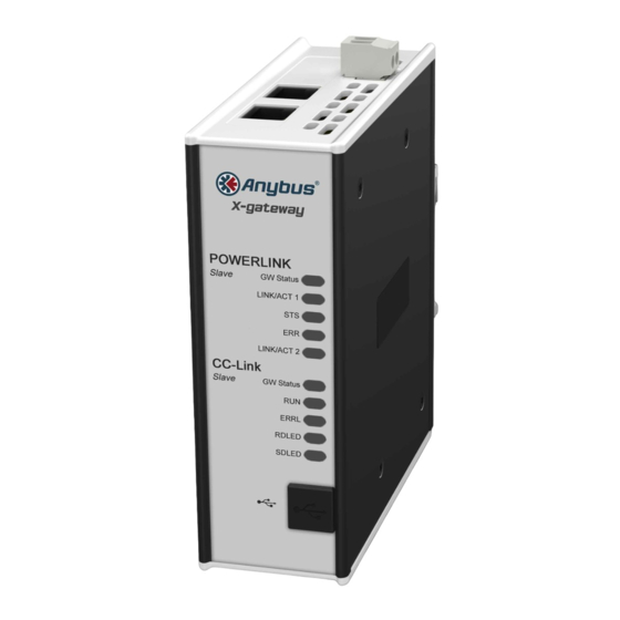
Status and Diagnostics Anybus-X LEDs There is a group of LED indicators on the front of the Anybus-X that is used to annunciate the current status of the module and the network interfaces. The layout of the LEDs is shown in Figure 8-1. - Page 74 Ethernet Link LED The Ethernet Link LED indicates that the module is connected to an Ethernet net- work. The LED will display solid green if there is a valid physical link. © 2005 HMS Industrial Networks AB7665 User manual...
- Page 75 Correct the problem and reset the Anybus-X. Flashing Red Recoverable A fault that can be corrected and does fault. not require a Anybus-X reset has been detected. Red,Green Self Test A self test of the module is in progress. Alternate Flashing...
-
Page 76: J1939 Status Codes
Status and Diagnostics 8-4 J1939 Status Codes The status codes for the J1939 interface are displayed by the Anybus-X Configu- ration Tool in the network configuration pane associated with the J1939 network. There are 2 status codes: a general status, and an error status. The general status is displayed as a textual status. -
Page 77: Diagnostic Web Pages
Diagnostic Web Pages Status and Settings Web Page The Status and Settings page displays the Anybus-X identification information, current status, and IP configuration. The IP configuration can be changed from this page. The module status is updated approximately every 2.5 seconds. -
Page 78: Specifications
EN50082-2-EMC Generic Immunity Standard, Part 2 - Industrial Envi- ronment This product is intended for use in an industrial environment. Electrical Specifications DC Power Operating voltage: 7-32v DC. Current Requirements: 130-140 mA at 24 VDC. © 2005 HMS Industrial Networks AB7665 User manual... -
Page 79: Mechanical Specifications
Specifications 9-2 Mechanical Specifications Mechanical Rating IP20/NEMA 1 Dimensions Figure 9-1 Anybus-X Mechanical Dimensions I/O Data Sizes Input Maximum 508 bytes Input Output Maximum 508 bytes Output Status 10 bytes of Status data © 2005 HMS Industrial Networks AB7665 User manual... -
Page 80: J1939 Specifications
Self-configurable using a list of addresses. Transport Protocol Sessions Support of J1939 transport protocol for large messages with the following limita- tions: •Single outgoing session (either BAM or RTS/CTS). •1 incoming BAM and 1 incoming RTS/CTS concurrently. © 2005 HMS Industrial Networks AB7665 User manual... -
Page 81: Connectors
Chapter 10 Connectors 10-1 Connectors Power Figure 10-1 Power Connector Connection 24 VDC + 24 VDC Common Table 10-1 Power Connector Pin Definitions MSTB 2,5/2-ST-5,08 ABGY Use Phoenix connector part number © 2005 HMS Industrial Networks AB7665 User manual... -
Page 82: J1939
Table 10-2 J1939 Connector Pin Definitions Use Phoenix connector part number MSTB 2,5/5-ST-5,08-ABGYAU. Note: The 24VDC connections on the J1939 and Power connectors are physically connected internally. The module may be powered from either set of pins. © 2005 HMS Industrial Networks AB7665 User manual... -
Page 83: Ethernet Rj45
Connectors 10-3 Ethernet RJ45 Signal Termination Termination Termination Termination Table 10-3 RJ45 Pinout © 2005 HMS Industrial Networks AB7665 User manual... -
Page 84: Configuration Rs-232 9 Pin D-Subminiature
Connectors 10-4 Configuration RS-232 9 Pin D-Subminiature Signal Receive Transmit Signal Ground Table 10-4 RS232 9 Pin © 2005 HMS Industrial Networks AB7665 User manual... -
Page 85: Warranty
Warranty 11-1 Warranty HMS Industrial Networks warrants all new products to be free of defects in material and workmanship when applied in the manner for which they were intended and according to HMS Industrial Networks’ published information on proper installation. The Warranty period is one year from the date of shipment. -
Page 86: Support
Chapter 12 Support 12-1 Support Technical Product Assistance If you need to contact HMS Industrial Networks for technical assistance, ask for Anybus-X technical support at: +46 (0) 35 17 29 00. You can obtain technical assistance by email at: support@anybus.com...
Need help?
Do you have a question about the Anybus-X and is the answer not in the manual?
Questions and answers