Table of Contents
Advertisement
Quick Links
Advertisement
Table of Contents

Related Manuals for HMS Anybus Communicator IIoT


Summary of Contents for HMS Anybus Communicator IIoT
- Page 1 ® ™ Anybus Communicator IIoT STARTUP GUIDE SP2444 1.0 en-US ENGLISH...
-
Page 2: Important User Information
The data and illustrations found in this document are not binding. We, HMS Industrial Networks AB, reserve the right to modify our products in line with our policy of continuous product development. The information in this document is subject to change without notice and should not be considered as a commitment by HMS Industrial Networks AB. -
Page 3: About This Document
Preface 3 (12) Preface About This Document This document describes how to install the Anybus Communicator IIoT. For additional documentation and software downloads, FAQs, troubleshooting guides and technical support, please visit www.anybus.com/support. Document Conventions The following formatting conventions are used in this document to indicate safety... -
Page 4: Installation Overview
Installation 4 (12) Installation Installation Overview Prerequisites The following items are required for installation and basic configuration: • Configuration cable • Subnetwork cable • Ethernet cable • Anybus Configuration Manager - Communicator RS-232/422/485 (4.5.0.0 or later) • Anybus Configuration Manager - IIoT •... -
Page 5: Din Rail Mounting
Installation 5 (12) DIN Rail Mounting The unit must be electrically grounded through the DIN rail for EMC compliance. Mount on DIN rail Fig. 1 Push down to mount or remove Hook the unit onto the upper lip of the rail and push gently downwards. Push the unit towards the rail until it snaps into place. -
Page 6: Connectors And Indicators
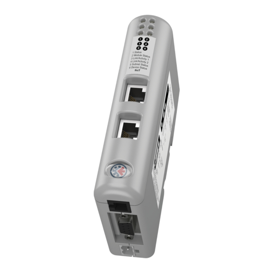
Installation 6 (12) Connectors and Indicators 2.3.1 Overview Fig. 2 Overview LED indicators DIN rail mount Power connector Serial subnetwork interface PC connector IIoT network interface Anybus ® Communicator ™ Startup Guide SP2444 1.0 en-US... -
Page 7: Serial Subnetwork Interface
Installation 7 (12) 2.3.2 Serial Subnetwork Interface Fig. 3 D-sub connector (DE-9F) Description RS-232 RS-422 RS-485 +5 V Output (100 mA max.) RS-232 Rx RS-232 Tx (reserved) Signal Ground RS-422 Rx + RS-422 Rx - RS-485 + / RS-422 Tx + RS-485 - / RS-422 Tx - Housing Shield... - Page 8 Installation 8 (12) 2.3.3 Power Connector (2 pin) Connecting power with reverse polarity or using the wrong type of power supply may damage the equipment. Make sure that the power supply is connected correctly and of the recommended type. Signal +24 VDC Power Ground 2.3.4 PC Connector (RJ11)
-
Page 9: Led Indicators
Installation 9 (12) LED Indicators LED 1 to 4 Model-specific information LED 5 Serial subnetwork status LED 6 Device status Indication Meaning Offline or no power Green Online, IP address assigned Green, flashing No IP address assigned or no link 1 - Network Status Fatal error, IP address conflict Alternating Red/Green... -
Page 10: Technical Data
Technical Data 10 (12) Technical Data General Specifications Model name Anybus Communicator IIoT Order code AB7079-B Dimensions (L x W x H) 120 x 75 x 27 mm Weight 150 g Operating temperature 0 to +55 °C (IEC 60068-2-1 and IEC 60068-2-2) Storage temperature -40 to +85 °C (IEC 60068-2-1 and IEC 60068-2-2) - Page 11 Technical Data 11 (12) IIoT Interface OPC UA functionality • Support for micro-embedded profile • Supports Discovery Services • Timestamp supported via discovery server • User name and password authentication • Supports DataChange Subscription • Maximum 80 data point tags (max.
- Page 12 © 2018 HMS Industrial Networks Box 4126 300 04 Halmstad, Sweden info@hms.se SP2444 1.0 en-US / 2018-11-22 / 10688...
Need help?
Do you have a question about the Anybus Communicator IIoT and is the answer not in the manual?
Questions and answers