HMS Anybus X-Gateway User Manual
Hide thumbs
Also See for Anybus X-Gateway:
- User manual (74 pages) ,
- Installation sheet (2 pages) ,
- User manual (46 pages)

Related Manuals for HMS Anybus X-Gateway


Summary of Contents for HMS Anybus X-Gateway
- Page 1 A A n n y y b b u u s s ® ® X X - - g g a a t t e e w w a a y y ™ ™ USER MANUAL HMSI-27-262 4.0 en-US ENGLISH...
- Page 2 HMS Industrial Networks reserves the right to modify its products in line with its policy of continuous product development. The information in this document shall therefore not be construed as a commitment on the part of HMS Industrial Networks and is subject to change without notice.
-
Page 3: Table Of Contents
Table of Contents Page Preface ..........................3 About This Document .......................3 Document history ......................3 Document Conventions .....................4 Document-specific Conventions..................4 Description .......................... 5 Introduction ........................5 Data Exchange.........................6 Status and Diagnostics ......................7 Controlling the X-gateway from the Network ................9 Error Handling .........................9 Data Mapping Examples .................... - Page 4 This page intentionally left blank...
-
Page 5: Preface
Preface 3 (16) Preface About This Document This document describes the functions and general configuration of the Anybus X-gateway. Documentation and software for the specific fieldbus and Ethernet network interfaces can be downloaded from www.anybus.com/support. Document history Date Version Description 1.00... -
Page 6: Document Conventions
This is a cross-reference within this document: Document Conventions, p. 4 This is an external link (URL): www.hms-networks.com This is additional information which may facilitate installation and/or operation. This instruction must be followed to avoid a risk of reduced functionality and/or damage to the equipment, or to avoid a network security risk. -
Page 7: Description
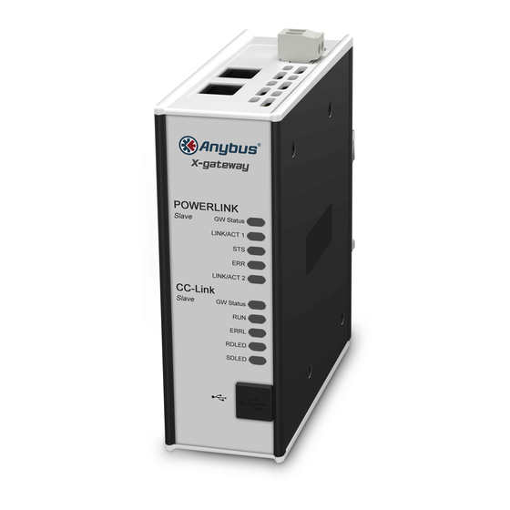
Description Introduction The Anybus X-gateway consists of two Anybus fieldbus or Ethernet network interface modules and an intelligent gateway platform which transfers data between the two networks. The X-gateway can be configured via a USB port using a Windows-based application, Anybus Configuration Manager. -
Page 8: Data Exchange
The terminology and definitions used for different types of data vary between different network types. Most networks distinguish between fast, cyclical I/O data, and less time-critical acyclic data. In the Anybus X-gateway these types of data are generally referred to respectively as I/O Data and Parameter Data. -
Page 9: Status And Diagnostics
Description 7 (16) Status and Diagnostics 2.3.1 Status Word Runtime status and diagnostic information can be provided through the Status Word, which (if enabled) takes up the first two bytes of the output area (data to the network). The Status Word is disabled by default and must be enabled for each network separately through Anybus Configuration Manager. - Page 10 Description 8 (16) 2.3.2 Live List (Master Configurations Only) The Live List provides the active status of the slaves associated with an on-board network interface acting as master. The list is assembled by the master interface and forwarded to the other network each gateway cycle.
-
Page 11: Controlling The X-Gateway From The Network
The exact definition depends on the network interface type. See the documentation for the respective interface for more information. Reset Can be used to reset the Anybus X-gateway. Bit set (1) = Restart the gateway and re-initialize both network interfaces Bit cleared (0) = No action 2.4.1... -
Page 12: Data Mapping Examples
Data Mapping Examples Usage of the Control Word, Status Word and Live List affect how data is mapped to the network interfaces in the Anybus X-gateway. The following generic examples describe typical configurations. The actual representation of data on the network is highly network-specific and is described in the documentation for the respective interface. -
Page 13: Installation
Installation 11 (16) Installation DIN Rail Mount The unit is designed to be mounted on a standard DIN rail. No tools are needed. The unit must be electrically grounded through the DIN rail for EMC compliance. Make sure that the unit is correctly mounted on the rail and that the rail is properly grounded. Fig. -
Page 14: Connectors And Indicators
Installation 12 (16) Connectors and Indicators Fig. 7 Connectors 3.2.1 Power Connector (X3) Connecting power with reverse polarity or using the wrong type of power supply may damage the equipment. Make sure that the power supply is connected correctly and of the recommended type. -
Page 15: Anybus Configuration Manager
Anybus Configuration Manager Introduction The Anybus X-gateway usually requires only a minimum of configuration during setup, since the on-board network interfaces are configured from the respective networks. Some parameters in the gateway may however need to be adjusted to suit specific networks and applications. -
Page 16: Setup
Anybus Configuration Manager 14 (16) Setup Download Anybus Configuration Manager and Anybus Transport Provider from www.anybus.com/support. Unzip the contents of each archive in a folder on your computer and double-click on the setup executable, then follow the instructions in the installation wizard. Connect a USB cable between the computer and the USB port on the X-gateway. -
Page 17: A Technical Data
Yes, on both network sides IP20, NEMA rating 1 Mechanical rating Mounting DIN rail (EN 50022) Network shield conductance via DIN rail Certifications www.anybus.com/support All measurements are in millimeters. Fig. 11 Anybus X-gateway dimensions HMSI-27-262 4.0 en-US Anybus ® X-gateway ™ User Manual... - Page 18 © 2019 HMS Industrial Networks Box 4126 300 04 Halmstad, Sweden info@hms.se HMSI-27-262 4.0 en-US / 2019-03-19 / 12401...
Need help?
Do you have a question about the Anybus X-Gateway and is the answer not in the manual?
Questions and answers