Table of Contents
Advertisement
Quick Links
Advertisement
Table of Contents

Related Manuals for HMS Anybus Modbus to KNX Gateway


Summary of Contents for HMS Anybus Modbus to KNX Gateway
- Page 1 Modbus to KNX Gateway USER MANUAL SCM-1202-050 1.2 en-US ENGLISH...
- Page 2 HMS Industrial Networks reserves the right to modify its products in line with its policy of continuous product development. The information in this document shall therefore not be construed as a commitment on the part of HMS Industrial Networks and is subject to change without notice.
-
Page 3: Table Of Contents
Table of Contents Page Preface ..........................3 About This Document .......................3 Document Conventions .....................3 Trademarks........................3 Safety ........................... 4 Product Description ......................5 General ..........................5 Operation ........................5 KNX Interface ........................6 Modbus Interface......................7 Installation........................... 9 Overview ........................9 Mechanical Installation ....................12 Connecting the KNX interface................... 13 Connecting the Modbus interface .................. - Page 4 This page intentionally left blank...
-
Page 5: Preface
Additional information which may facilitate installation and/or operation. Trademarks ® Anybus is a registered trademark of HMS Industrial Networks. All other trademarks mentioned in this document are the property of their respective holders. SCM-1202-050 1.2 en-US Modbus to KNX Gateway User Manual... -
Page 6: Safety
Safety 4 (32) Safety Connecting power with reverse polarity or using the wrong type of power supply may damage the equipment. Make sure that the power supply is connected correctly and of the recommended type. This product contains parts that can be damaged by electrostatic discharge (ESD). Use ESD prevention measures to avoid damage. -
Page 7: Product Description
Product Description General The Anybus Modbus to KNX Gateway is intended for integration of Modbus RTU and Modbus TCP installations into KNX monitoring and control systems. On the KNX side the gateway acts as a KNX device, and on the Modbus side it emulates a Modbus RTU Master device and/or a Modbus TCP Client device. -
Page 8: Knx Interface
Product Description 6 (32) KNX Interface The gateway connects directly to the KNX TP-1 (EIB) bus and behaves as one more device in the KNX system, with the same configuration and operational characteristics as other KNX devices. Internally, the circuit part connected to the KNX bus is opto-isolated from the rest of the electronics. -
Page 9: Modbus Interface
Product Description 7 (32) Modbus Interface Modbus TCP basically embeds the Modbus RTU protocol in TCP/IP frames. TCP/IP allows faster communication and a longer distance between the master and slave devices than RTU communication over serial line. Modbus TCP allows communication over an existing TCP/IP infrastructure such as a LAN, WAN or the Internet. - Page 10 Product Description 8 (32) 3.4.1 Modbus Points Definition Each point defined in the gateway has the following Modbus features associated to it: Feature Description Modbus Device Modbus TCP device to which belongs the point, from a list of Modbus TCP slave devices that can be defined in the gateway (up to 5).
-
Page 11: Installation
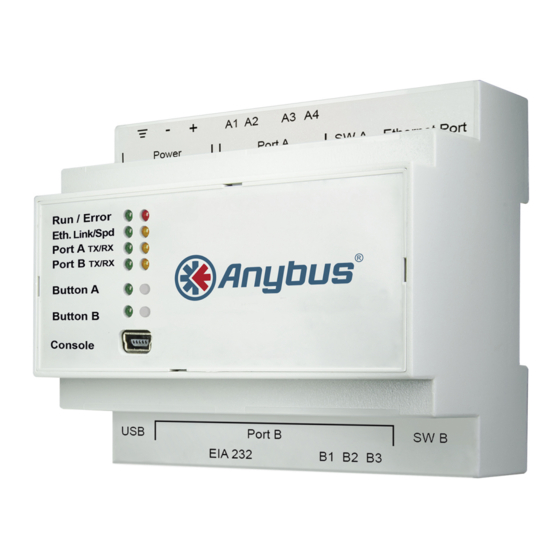
Installation 9 (32) Installation Overview Fig. 1 Front panel Read the Safety before starting installation. Installation Procedure These are the main steps when installing and setting up the Modbus to KNX Gateway. Each step will be described in the following sections of this document. Mount the gateway on a DIN rail or using the screw mounting clips. - Page 12 Installation 10 (32) Connectors Technical Data, p. 31 regarding terminal wiring and power supply requirements. Power Connector (3-pole terminal block) Function Protective Earth Power Ground 24 VAC or +9 to +36 VDC Port A / KNX (2-pole terminal block) Function A1, A2 Not used KNX +...
- Page 13 Installation 11 (32) LED Indicators Fig. 2 Overview Indication Meaning Green Normal operation Error Operating error Eth Link Green 100 Mbit/s Ethernet Yellow 10 Mbit/s Ethernet Flashing Ethernet traffic Green Eth Spd Full-duplex Ethernet mode Half-duplex Ethernet mode Flashing Packet collision Port A Tx Green Transmitting on Port A...
-
Page 14: Mechanical Installation
Installation 12 (32) Mechanical Installation The unit should be mounted on a standard DIN rail or screw-mounted onto a flat surface inside a properly grounded metallic enclosure. The unit should not be mounted outdoors or exposed to direct sunlight, water, high humidity or dust. Make sure that there is enough space for the connectors and that the LED indicators and configuration switches are accessible after the unit is mounted. -
Page 15: Connecting The Knx Interface
Installation 13 (32) Connecting the KNX interface Connect the KNX TP1 bus to Port A on the gateway. Observe the correct polarity of the connections, see Connectors, p. If there is no response on the KNX interface, check that the devices on the bus are connected and operating correctly, and that traffic to/from the gateway is not restricted. -
Page 16: Connecting The Power Supply
Installation 14 (32) Connecting the Power Supply Connect a suitable power supply to the Power terminal. See Technical Data, p. 31 regarding the power supply requirements. Observe the correct polarity of the connections, see Connectors, p. Configuration Connections Connect the computer to be used for configuration to the Console port on the front panel of the gateway using a standard USB type B cable. -
Page 17: Anybus Configuration Manager (Maps)
Anybus Configuration Manager (MAPS) 15 (32) Anybus Configuration Manager (MAPS) ® Anybus Configuration Manager (MAPS) is a free Windows -based software tool which is used to monitor and configure the AnybusModbus to KNX Gateway. Installation Make sure that you have all the necessary information about the capabilities and restrictions of your local network environment before installing and using this software. -
Page 18: Connection Tab
Anybus Configuration Manager (MAPS) 16 (32) Connection Tab Anybus Configuration Manager (MAPS) can communicate with the gateway either over an Ethernet network or directly via the Console USB port. Projects can be created when the gateway is offline and then downloaded to the unit once a connection has been established. 5.2.1 Connection Mode When this option is selected the computer used for configuration must be connected to the... - Page 19 Anybus Configuration Manager (MAPS) 17 (32) USB Port Select this option if the computer used for configuration is connected directly to the gateway via the Console USB port. All the available serial (COM) ports on the computer will be listed. Fig.
-
Page 20: Configuration Tab
Anybus Configuration Manager (MAPS) 18 (32) Configuration Tab Fig. 9 Configuration tab 5.3.1 General General Configuration Gateway Name Used for easy identification of the unit in the project. This entry is only informational and can be edited freely. Project Description A brief description of the project. - Page 21 Anybus Configuration Manager (MAPS) 19 (32) Conversions Edit Conversions Allows you to define customized unit conversions and value filters to be used in the integration project. See also . Fig. 10 Conversions Manager SCM-1202-050 1.2 en-US Modbus to KNX Gateway User Manual...
- Page 22 Anybus Configuration Manager (MAPS) 20 (32) 5.3.2 This section contains settings related to KNX communication. Fig. 11 KNX configuration Device Configuration Physical Address Sets the KNX Physical Address (Individual Address) of the gateway. This is a unique identifier for the gateway inside a single KNX TP-1 segment. The maximum value is 15.15.255.
- Page 23 Anybus Configuration Manager (MAPS) 21 (32) 5.3.3 Modbus Master This section contains all settings related to Modbus communication. Fig. 12 Modbus master configuration Gateway Configuration Select the type of Modbus communication required for the Modbus slave devices: Modbus RTU Modbus connection over the EIA-485 serial port. Modbus TCP Modbus connection over Ethernet.
- Page 24 Anybus Configuration Manager (MAPS) 22 (32) RTU Devices Configuration Different device and node configuration options are available depending on if Modbus TCP or Modbus RTU communication is selected. Modbus RTU The following parameters must be configured for each RTU node: Baudrate The communication speed for RTU communication.
- Page 25 Anybus Configuration Manager (MAPS) 23 (32) Modbus TCP For Modbus TCP the following standard parameters must be configured: Fig. 15 Modbus TCP node configuration TCP Node Name Descriptive device name TCP Node IP IP address for the Modbus server to connect TCP Node Port Port for the Modbus server to connect (default = 502) Add Device(s)
- Page 26 Anybus Configuration Manager (MAPS) 24 (32) Modbus Poll Records The gateway allows the use of Modbus Poll Records. Fig. 16 Modbus poll records Allow using Poll Records with missing If enabled, it allows nonconsecutive registers to be grouped in the same Poll registers Record.
-
Page 27: Signals Tab
Anybus Configuration Manager (MAPS) 25 (32) Signals Tab This section contains settings for the signals on both protocols. Fig. 17 Signals tab 5.4.1 Common and KNX Signal Parameters The following common and KNX specific parameters can be configured for each signal. Active If checked, the signal will be considered in the configuration and will be downloaded to the Gateway as active. - Page 28 Anybus Configuration Manager (MAPS) 26 (32) 5.4.2 Signals View Settings The controls at the bottom of the Signals view can be used to customize the column layout and when importing and exporting configurations. Fig. 18 Signals view settings Edit Columns Allows you to select which columns to display in the list.
-
Page 29: Receive/Send Tab
Anybus Configuration Manager (MAPS) 27 (32) Receive/Send Tab 5.5.1 Send Send the current project configuration to the gateway. If the project has not been saved you will be prompted to save it before sending. Fig. 19 Send configuration 5.5.2 Receive Downloads the active configuration from the connected gateway to the Anybus Configuration Manager (MAPS). -
Page 30: Diagnostic Tab
Anybus Configuration Manager (MAPS) 28 (32) Diagnostic Tab The Diagnostic view can be used for analysis and troubleshooting when building and implementing configuration projects. Multiple Viewers can be added to the interface to monitor communication on the protocols as well as general gateway information. Fig. - Page 31 Anybus Configuration Manager (MAPS) 29 (32) 5.6.2 Viewers The data in each viewer is updated in real time when the gateway is connected and active. If the gateway is disconnected, the last received data will remain in the viewer until cleared. The viewers can be rearranged in the window by clicking and dragging.
- Page 32 Anybus Configuration Manager (MAPS) 30 (32) Signals Viewer The Signals viewer displays all active signals in the gateway with its main configuration parameters and its real-time value (if connected). To manually refresh the values, click on . This may be necessary if the gateway has already been running for some time.
-
Page 33: A Technical Data
Appendix A: Technical Data 31 (32) Technical Data General Model name Anybus Modbus to KNX Gateway Order code AB9901-nnnn (nnnn = number of datapoints) 90 x 88 x 56 mm Dimensions (L x W x H) Operating temperature 0 to +60 °C Storage temperature -40 to +85 °C... - Page 34 © 2019 HMS Industrial Networks Box 4126 300 04 Halmstad, Sweden info@hms.se SCM-1202-050 1.2 en-US / 2019-06-27 / 13819...
Need help?
Do you have a question about the Anybus Modbus to KNX Gateway and is the answer not in the manual?
Questions and answers