Table of Contents
Advertisement
User Manual
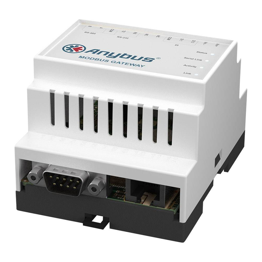
Anybus® Modbus-TCP/RTU Gateway
AB7702
Doc.Id. HMSI-168-77
Rev. 2.03
Connecting Devices
+$/067$' ‡ &+,&$*2 ‡ .$5/658+( ‡ 72.<2 ‡ %(,-,1* ‡ 0,/$12 ‡ 08/+286( ‡ &29(175< ‡ 381( ‡ &23(1+$*(1
HMS Industrial Networks
Mailing address: Box 4126, 300 04 Halmstad, Sweden
E-mail: info@hms-networks.com
Visiting address: Stationsgatan 37, Halmstad, Sweden
Web: www.anybus.com
Advertisement
Table of Contents

Related Manuals for HMS Anybus Modbus-TCP/RTU Gateway


Summary of Contents for HMS Anybus Modbus-TCP/RTU Gateway
- Page 1 Rev. 2.03 Connecting Devices +$/067$' ‡ &+,&$*2 ‡ .$5/658+( ‡ 72.<2 ‡ %(,-,1* ‡ 0,/$12 ‡ 08/+286( ‡ &29(175< ‡ 381( ‡ &23(1+$*(1 HMS Industrial Networks Mailing address: Box 4126, 300 04 Halmstad, Sweden E-mail: info@hms-networks.com Visiting address: Stationsgatan 37, Halmstad, Sweden...
-
Page 2: Table Of Contents
Table of Contents Table of Contents Preface About This Document How To Use This Document......................P-1 Important User Information....................... P-1 Document History ..........................P-2 Conventions & Terminology ......................P-2 Sales and Support ..........................P-3 Chapter 1 About the Anybus® Modbus TCP/RTU Gateway General Information ..........................1-1 Mounting..............................1-2 Connectors .............................1-3... -
Page 3: Preface
For more information, documentation etc., please visit the HMS web site, ‘www.anybus.com’. Important User Information The data and illustrations found in this document are not binding. We, HMS Industrial Networks AB, reserve the right to modify our products in line with our policy of continuous product development. The information in this document is subject to change without notice and should not be considered as a com- mitment by HMS Industrial Networks AB. -
Page 4: Document History
About This Document P-2 Document History Summary of Recent Changes (2.02 ... 2.03) Change Page(s) Changed maxed supply voltage level from 32 V to 28 V 1-3, A-1 Changed UL file number Revision List Revision Date Author Chapter Description ..1.13 In Microsoft Word 2.00 2009-10-09... -
Page 5: Sales And Support
About This Document P-3 Sales and Support Sales Support HMS Sweden (Head Office) E-mail: sales@hms-networks.com E-mail: support@hms-networks.com Phone: +46 (0) 35 - 17 29 56 Phone: +46 (0) 35 - 17 29 20 Fax: +46 (0) 35 - 17 29 09... -
Page 6: About The Anybus® Modbus Tcp/Rtu Gateway
Chapter 1 About the Anybus® Modbus-TCP/RTU Gateway General Information The Anybus® Modbus-TCP/RTU Gateway can be used to connect a Modbus/TCP master to one or several Modbus/RTU slaves. The transparent Modbus TCP/RTU gateway will act as a Modbus/TCP slave on an Ethernet network, and transform the queries to the Serial Modbus network, and send back the Modbus/RTU slave response to the Modbus/TCP master. -
Page 7: Mounting
About the Anybus® Modbus-TCP/RTU Gateway 1-2 Mounting A - Snap on B - Snap off 1. Snap the Anybus module on to the DIN-rail (as described in picture A above). 2. Connect the Ethernet cable to the RJ45 connector. 3. Connect the Modbus/RTU network to the DSUB connector (RS-232) or through the screw ter- minal block (RS-485) 4. -
Page 8: Connectors
About the Anybus® Modbus-TCP/RTU Gateway 1-3 Connectors Modbus/RTU Interface, RS-232 The 9-pole DSUB, male connector on the Anybus module contains a fully equipped RS-232 interface. This port can be used to connect to any equipment with an RS-232 interface. Pin no Function CD (Carrier Detect) Rx (Receive) -
Page 9: Digital Inputs
About the Anybus® Modbus-TCP/RTU Gateway 1-4 Digital Inputs The digital inputs are opto-isolated, and can accept a 10-24 VDC signal for logic HIGH input. For logic LOW the voltage should be in the range 0-2 VDC. The status of the inputs can be read in the Gateway Internal Registers (if enabled). See 2-7 “Internal Registers”... -
Page 10: Chapter 2 Configuration
Chapter 2 Configuration Configure the IP address About the Anybus IPConfig utility The IPConfig utility is a PC-based configuration utility to set TCP/IP network settings in the Anybus module. Anybus IPConfig scans the Ethernet network for connected Anybus devices and lets the user set IP-address, net mask, gateway, DNS and host name for each unit. - Page 11 Configuration 2-2 Connecting the Anybus® Modbus-TCP/RTU Gateway to a hub or a switch Anybus Modbus TCP/RTU gateway Connecting the Anybus® Modbus-TCP/RTU Gateway directly to a PC Anybus Modbus TCP/RTU gateway When the Anybus IPConfig utility is started, it will scan the Ethernet network for Anybus devices. All detected devices will be presented in a list in the main window.
-
Page 12: Changing Ip Settings
Configuration 2-3 Changing IP Settings To change the IP settings of a detected device, double-click on the device you want to configure in the list of devices.This will open a dialogue where you can enter the desired IP configuration. To obtain the necessary information about IP address, Subnet mask etc. - Page 13 Configuration 2-4 The login screen should appear: To be able to configure the gateway you should enter “admin” in the user name box. This is the default password and can be changed at a later stage. If you have problems to log in and you are sure that your password is correct, make sure that Caps Lock is not enabled on your keyboard.
-
Page 14: Network Settings
Configuration 2-5 Network Settings Choosing “Network” will give the opportunity to view and change the TCP/IP settings in the module. These settings are the same as the ones defined in Anybus IPConfig. DHCP: Select this if you have a DHCP server on our network and you want the IP address to be as- signed automatically by the server. -
Page 15: Modbus Configuration
Configuration 2-6 Modbus Configuration Choosing “Config” will give the opportunity to configure Modus. Serial settings (Modbus RTU/ Comment ASCII) Transmission Mode RTU or ASCII Slave Response Time out Default value 200ms Physical Interface EIA-485 or EIA-232 Baud Rate 300, 600, 1200, 2400, 4800, 9600, 19200, 38400, 57600 or 115200 bps Character Format Select number of stop bits and if parity should be enabled (odd or even) Extra delay between messages... -
Page 16: Internal Registers
Configuration 2-7 Internal Registers If Gateway Registers are enabled, queries sent to those addresses will not be forwarded to the Serial Modbus/RTU network, but handled by the gateway. Register Name Values Options Comment Digital input 1 status 0 or 1 Read only Digital input 2 status 0 or 1... -
Page 17: Password Settings
Configuration 2-8 Register Name Values Options Comment Number of stop bits 1 - 2 Default: 1 stop bit Slave time out time 25 - 65535 ms Default: 1000 ms Physical interface 0 - 2 EIA-485 Default (Screw termi- nal block) EIA-232 (DSUB) EIA-232... -
Page 18: Status
Configuration 2-9 Status The following status information is available on the Status web page: Info Description Number of connections Number of masters that are connected to the module Valid Responses Counts valid responses from the Modbus/RTU slaves Serial Time outs Number of Modbus/RTU slave time outs CRC Errors Number of CRC errors on incoming Modbus/RTU responses... -
Page 19: Appendix A Specifications
Appendix A Specifications Ethernet Connection 10BASE-T or 100BASE-TX (IEEE 802.3). RJ45 connector. Serial Interfaces EIA-232 with full modem control (RTS, CTS, DCD, DTR, DSR, RI), 300-115200 bps, 9-pole DSUB connector EIA-485, 300-115200 bps, connection through screw terminal block Power Supply 9 - 28 VAC/DC 70 mA@24 VDC (1.7 W). -
Page 20: Certifications
Specifications A-2 Certifications CE Certification EN 50081-2:1993 EN 1000-6-2:1999 UL Certification The module is UL and cUL certified according to UL file number E214207. For more information see www.anybus.com. Anybus® Modbus TCP/RTU Gateway Doc.Id. HMSI-168-77 Doc.Rev. 2.03...
Need help?
Do you have a question about the Anybus Modbus-TCP/RTU Gateway and is the answer not in the manual?
Questions and answers