Table of Contents
Advertisement
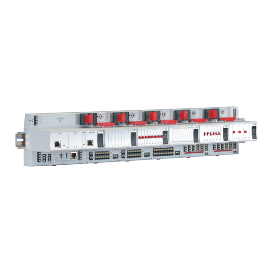
LION Controller
CONTENTS
Safety Information ............................................................. 3
General Safety Information ............................................ 3
Safety Information as per EN60730-1........................... 3
System Overview............................................................... 4
System Architecture....................................................... 4
I/O Modules ................................................................... 5
Interfaces and Bus Connections .................................... 9
Technical Data............................................................... 9
Planning ........................................................................... 10
Overview...................................................................... 10
Transformer Selection ................................................. 10
Fusing Specifications ................................................... 11
System Protective Earth Grounding............................. 11
Lightning Protection ..................................................... 11
Panel Bus Topologies .................................................. 11
Bus Topologies.......................................... 12
C-Bus Topologies ........................................................ 12
Accessories ................................................................. 12
Cable Specifications .................................................... 13
Dimensions .................................................................. 16
Mounting/Dismounting Modules .................................... 18
Mounting/Dismounting Controller/Sockets ................... 18
Mounting/Dismounting Electronic Modules .................. 20
Mounting/Dismounting Cross Connectors.................... 23
Mounting/Dismounting Swivel Label Holders............... 23
Wiring and Setting Up the System ................................. 24
General Safety Considerations .................................... 24
Wiring Push-in Terminals............................................. 24
Connecting Power Supply............................................ 25
Connecting Single Bus Controller Systems ................. 26
Connecting Panel Bus and L
Controller Systems ...................................................... 27
Setting Address of Panel Bus I/O Modules .................. 29
Copyright © 2009 Honeywell GmbH All Rights Reserved
Bus Mixed
Installation &
Commissioning
Instructions
INSTALLATION AND COMMISSIONING INSTRUCTIONS
Setting I/O Bus Switch ................................................. 29
Connecting Field Devices ............................................ 30
Commissioning I/O Modules ........................................ 31
Updating Software ....................................................... 31
Connecting to External Systems or Interfaces ............. 32
Connecting via C-Bus .................................................. 33
Connecting HMIs or Laptops ....................................... 33
Connecting Modems .................................................... 33
Description of the CLLIONLC01 ..................................... 34
Overview...................................................................... 34
Features....................................................................... 35
Description of the I/O Modules....................................... 40
Common Features ....................................................... 40
Analog Input Modules .................................................. 40
Analog Output Modules ............................................... 45
Binary Input Modules ................................................... 50
Relay Output Modules ................................................. 53
Floating Output Module................................................ 58
Mixed Panel Bus I/O Module CLIOP830A ................... 62
Description of Extra Parts............................................... 65
Manual Disconnect Modules ........................................ 65
XS814 Auxiliary Terminal Package.............................. 66
XS830 Auxiliary Terminal Package.............................. 66
XS831 Auxiliary Terminal Package.............................. 66
Cross Connectors ........................................................ 67
XAL10 Swivel Label Holders........................................ 67
XAL11 Swivel Label Holders........................................ 67
XS816 Bridge Connectors ........................................... 67
LON Software Interface Description .............................. 68
Overview...................................................................... 68
CLIOL821A Analog Input Module ................................ 68
CLIOL(R)822A Analog Output Module......................... 70
CLIOL823A Binary Input Module ................................. 72
CLIOL(R)824A Relay Output Module........................... 73
3.4
LION
SYSTEM
Bus.................................... 32
EN1Z-0921GE51 R0709
Advertisement
Table of Contents
Troubleshooting

Related Manuals for Honeywell CENTRA LINE LION CLLIONLC01


Summary of Contents for Honeywell CENTRA LINE LION CLLIONLC01
-
Page 1: Table Of Contents
CLIOL(R)822A Analog Output Module......70 ORKS Controller Systems ............27 CLIOL823A Binary Input Module ......... 72 Setting Address of Panel Bus I/O Modules ....29 CLIOL(R)824A Relay Output Module......73 Copyright © 2009 Honeywell GmbH All Rights Reserved EN1Z-0921GE51 R0709... - Page 2 LION System Troubleshooting...............74 Testing Wiring Connections..........74 Troubleshooting on the CLLIONLC01 Controller ..74 I/O Modules Troubleshooting........78 Appendix 1: System Protective Earth Grounding ..82 LION Systems and SELV ..........82 LION Systems and Standard EN60204-1.....82 Earth Grounding of EN60204-1 Applicable Systems ..82 Appendix 2: Remote Communications......84 Approved Modems ............84 Modem or ISDN Terminal Adapter Connection ....84 Modem Requirements ..........84...
-
Page 3: Safety Information
LION System Safety Information General Safety Information Safety Information as per EN60730-1 When performing any work (installation, mounting, start- ► up), all instructions given by the manufacturer and in Purpose particular the safety instructions provided in these The LION System is an independently mounted electronic Installation and Commissioning Instructions are to be control system with fixed wiring. -
Page 4: System Overview
System Overview LION System System Overview System Architecture An LION System consists of the CLLIONLC01 Controller and various I/O modules. The CLLIONLC01 Controller provides interface connections, which allow connection to external systems. Auxiliary parts enable special features. Panel I/O (CLIOPxx) Panel Bus (<40 m) existing XL500 controllers... -
Page 5: I/O Modules
LION System System Overview I/O Modules Terminal Sockets Pluggable I/O modules are mounted on the appropriate terminal sockets. Pluggable Panel Bus I/O modules and Variants of Pluggable I/O Modules pluggable L Bus I/O modules use the same ORKS There are 2 variants of pluggable I/O modules: terminal sockets. - Page 6 System Overview LION System I/O Module Overview Panel Bus ORKS Description Inputs Outputs Manual controls LEDs module Bus module CLIOP821A CLIOL821A Analog input module – – – CLIOP822A CLIOL822A Analog output module – – 8 status LEDs CLIOPR822A CLIOLR822A Analog output module –...
- Page 7 LION System System Overview Auxiliary Parts Corresponding Module Type Figure I/O modules Information CLIOP/CLIOL… …821 Module allows disconnection of XS812 …822 individual I/O signals …823 Manual disconnect modules Module allows disconnection of …824 individual I/O signals XS812RO …825 For 24 V applications only Two groups of 7 terminals All pluggable LION I/O connected to each other for...
- Page 8 System Overview LION System Corresponding Module Type Figure I/O modules Information CLIOP/CLIOL… …824 Cross connectors, long XS815 Connects 6 relay commons (red) …825 Connects CLLIONLC01 and I/O Connector bridge XS816 All LION I/O modules modules Can be plugged into socket, for All pluggable LION I/O Swivel label holder XAL10...
-
Page 9: Interfaces And Bus Connections
LION System System Overview Interfaces and Bus Connections Standards The LION System can be connected to the following devices Protection class IP20 and systems: Product standard EMC EN 60730-2-9 Panel Bus Testing electrical IEC68 components • For communication with up to 16 Panel Bus I/O modules •... -
Page 10: Planning
Planning LION System Planning Overview Transformer Selection Engineering with CARE During CARE engineering, the type of I/O modules, terminal Note assignment and module configuration are defined In Europe the system transformer(s) must be safety isolating depending on the application. The same applies to transformers according to IEC61558-2-6. -
Page 11: Fusing Specifications
LION System Planning CentraLine 1450 Series (North America) Power Supply of Field Devices • 50/60 Hz Depending upon the power consumption of the field devices • Insulated accessory outputs used, it is possible to use either a single transformer to power both the CLLIONLC01 and attached field devices, or •... -
Page 12: Lon Works Bus Topologies
Planning LION System Bus Topologies Accessories ORKS The L Bus is a 78-kilobit serial link that uses Besides the auxiliary parts of Table 5 on page 7, the ORKS transformer isolation so that the bus wiring does not have a following accessories are available. -
Page 13: Cable Specifications
LION System Planning XW885 Cable Details Bus Termination Modules ORKS RJ45 plug with clip at front RS232 plug SHIELD sub-D female Type Description 209541 Bus termination module ORKS XAL-Term connection and ORKS termination module, which can be mounted on DIN rails and in fuse boxes XW885 Table 15 L... - Page 14 Planning LION System Note Bus Cables ORKS In the event that the limit on the total wire length is exceeded, the FTT physical layer repeaters (FTT 10A) can be added to interconnect segments. This increases the Cable type Max. bus length overall length by an amount equal to the original Belden 85102 (plenum) 2700 m (8900 ft)
- Page 15 LION System Planning C-Bus Cables Note Observe national regulations for C-Bus cables! • For Europe only shielded cable is permitted. • For the U.S. shielded or unshielded cable can be used. Cable type Description Recommended for J-Y-(ST)Y shielded, Europe, inside cabinet 2 x 2 x 0.8 twisted pair A-Y-(ST)Y...
-
Page 16: Dimensions
Planning LION System Dimensions Controller Module 92.75 Fig. 11 Controller module, outside dimensions (in mm) Pluggable I/O Modules 89.5 94.1 LOCK SCREW-TYPE 30.6 TERMINALS SWIVEL LABEL HOLDER XS814 Aux. Terminal Package (optional) 51.5 Fig. 12 Pluggable I/O modules (shown with manual overrides), including XS814 Aux. Terminal Package, dimensions (in mm) EN1Z-0921GE51 R0709... - Page 17 LION System Planning Mixed I/O Module 92.5 COM a COM a External COM b COM b 24V~ 24V~ 24V~0 24V~0 24V for relay 1...5 Binary Inputs Analog Inputs Analog Outputs 24V Relays B8 B9 B10 B11 B12 AI5 AI6 AI7 AI8 AO6 AO7 AO8 IN1 IN2 IN3 IN4 IN5 IN6 10 11 12 18 19 20...
-
Page 18: Mounting/Dismounting Modules
Mounting/Dismounting Modules LION System Mounting/Dismounting Modules Mounting/Dismounting Controller/Sockets WARNING Risk of electric shock or equipment damage! Mounting Sockets Do not touch any live parts in the cabinet. ► Disconnect the power supply before you start to install ► the LION System. Notes More than one disconnect switch may be required to de- •... - Page 19 LION System Mounting/Dismounting Modules Angle the terminal socket at the upper edge of the DIN Connecting Sockets ► rail until it snaps in. Controller, terminal sockets, and mixed I/O modules on the Swing the terminal socket down and apply gentle force ►...
-
Page 20: Mounting/Dismounting Electronic Modules
Mounting/Dismounting Modules LION System Mounting/Dismounting Electronic Modules Dismounting Sockets Disconnecting Sockets Mounting Electronic Modules Release all bridge connectors before removing the controller module and/or the terminal sockets and/or mixed I/O modules from the DIN rail. Note Electronic modules can be removed from the socket or Press down at the same time both the gray side wings ►... -
Page 21: Mounting/Dismounting Manual Disconnect Modules
LION System Mounting/Dismounting Modules Mounting/Dismounting Manual Disconnect Dismounting Electronic Modules Modules Note XS812 and XS812RO Manual Disconnect Modules are Electronic modules can be removed from the socket or mounted on the terminal socket appropriate for the inserted into the sockets without switching off the power electronic module, see Table 4 on page 6. -
Page 22: Mounting/Dismounting Auxiliary Terminal Packages
Mounting/Dismounting Modules LION System Mounting/Dismounting Auxiliary Terminal Operating the Individual Switches Packages Use a screwdriver to open/close the appropriate ► disconnector switches of the manual disconnect modules. The XS814 Auxiliary Terminal Package can be mounted on any pluggable I/O module. The XS830 and XS831 Auxiliary Terminal Packages are suitable for mixed I/O modules, only. -
Page 23: Mounting/Dismounting Cross Connectors
LION System Mounting/Dismounting Modules Mounting/Dismounting Cross Connectors Mounting/Dismounting Swivel Label Holders Note The long cross connector (incl. in the scope of the delivery) Note can be mounted to the XS824-25 or XSU824-25, as A swivel label holder is included in the scope of delivery of required (Fig. -
Page 24: Wiring And Setting Up The System
Wiring and Setting Up the System LION System Wiring and Setting Up the System General Safety Considerations Wiring Push-in Terminals • When connecting the CLLIONLC01 or LION I/O modules, The terminal sockets of the pluggable I/O modules are available in versions (…82…) featuring convenient push-in both VDE, National Electric Code (NEC) or equivalent, terminals for easy wiring. -
Page 25: Connecting Power Supply
LION System Wiring and Setting Up the System Connecting Power Supply Additional Transformer Connect the additional transformer in a second room or ► The LION System can be powered by one or more external cabinet to terminals 73 and 74 or 77 and 78 of an transformers. -
Page 26: Connecting Single Bus Controller Systems
Wiring and Setting Up the System LION System Connecting Single Bus Controller Systems Panel Bus I/O Modules in Separate Rooms In this scenario, communication and reference voltage This section describes how to connect a controller system (24 V0) must be connected between the rooms. which uses Panel Bus I/O modules only or L ORKS Connect the last module of room 1 to the first module of... -
Page 27: On Works
LION System Wiring and Setting Up the System Connecting Panel Bus and L LonWorks Bus I/O Modules in Separate Rooms ORKS Mixed Controller Systems In this scenario, only communication lines must be connected between the rooms. Connect the last module of room 1 to the first module of Connecting I/O Modules with Each Other ►... - Page 28 Wiring and Setting Up the System LION System Panel Bus I/O modules Panel Bus I/O modules CLLIONLC01 XF... LonWorks Bus I/O modules Fig. 36 Mixed bus system – correct wiring Panel Bus I/O modules LonWorks Bus modules CLLIONLC01 Fig. 37 Mixed bus system –...
-
Page 29: Setting Address Of Panel Bus I/O Modules
LION System Wiring and Setting Up the System Setting Address of Panel Bus I/O Modules Setting I/O Bus Switch During engineering, each Panel Bus I/O module is assigned Set the I/O Bus switch S2 of the CLLIONLC01 depending ► its own unique address. For the sake of clarity for on the modules connected to terminals 71 …... -
Page 30: Connecting Field Devices
Wiring and Setting Up the System LION System Connecting Field Devices Cabling Field Devices Connecting Field Devices with Power Supply Cable Routing Depending on the distance from the controller, field devices Route low-voltage signal and output cables separately from can be supplied by the controller or need a separate mains cables. -
Page 31: Commissioning I/O Modules
LION System Wiring and Setting Up the System Commissioning I/O Modules Commissioning Panel Bus I/O Modules During engineering, the HEX address of the Panel I/O modules is defined. Note With Panel Bus I/O modules it is essential that the HEX switch be set to the address assigned by the engineering tool. -
Page 32: Connecting To External Systems Or Interfaces
Connecting to External Systems or Interfaces LION System Connecting to External Systems or Interfaces Termination Examples WARNING Risk of electric shock or equipment damage! Do not touch any live parts in the cabinet! ► Brown Brown Disconnect the power supply before making connections ►... -
Page 33: Connecting Via C-Bus
LION System Connecting to External Systems or Interfaces Connecting via C-Bus Connecting HMIs or Laptops Via C-Bus, a LION Controller can be connected to other HMIs (e.g., the CLMMI00N22 or the CLMMI00N31) can be controller systems to form a network. connected via the HMI interface of the CLLIONLC01. -
Page 34: Description Of The Cllionlc01
Description of the CLLIONLC01 LION System Description of the CLLIONLC01 Overview Panel I/O (CLIOPxx) Panel Bus (<40 m) existing XL500 controllers CLLIONLC01 + CLIOxx C-Bus LonWorks Bus MODEM CLMMI00N22 or CLMMI00N31 LonWorks I/O (CLIOLxx) XFCxxx XFCLxxx SERVAL Fig. 46 Connections to the CLLIONLC01 Controller Legend Power supply for I/O modules I/O Bus communication terminals... -
Page 35: Features
LION System Description of the CLLIONLC01 Features CLLIONLC01 Terminals Interface and Terminals ORKS The CLLIONLC01 Controller Module features • An RJ45 socket serving as an interface to connect laptops to the L ORKS 8 7 6 5 4 3 2 1 •... - Page 36 Description of the CLLIONLC01 LION System C-Bus Tx LED and Rx LED HMI Interface The CLLIONLC01 is equipped with a Tx LED (status: The controller module is equipped with an HMI Interface for yellow/OFF) and an Rx LED (status: yellow/OFF). the connection of HMIs (e.g., the CLMMI00N22 or the CLMMI00N31) or a laptop (with XL-Online/CARE).
- Page 37 LION System Description of the CLLIONLC01 Power LED (2, green) Alarm and Power LEDs Normal operation The CLLIONLC01 is equipped with an alarm LED and a Flashing One or more of the internal voltage power LED. supplies are outside of the permissible ranges.
- Page 38 Description of the CLLIONLC01 LION System Modem Interface I/O Bus Switch S2 The controller module is equipped with a modem interface The CLLIONLC01 features a 2-position I/O Bus switch S2. for the connection of a modem or an ISDN terminal adapter. I/O Bus switch S2 must be set in accordance with the kind of I/O modules connected to communication terminals 71, 72 and 75, 76 of the controller module.
- Page 39 LION System Description of the CLLIONLC01 C-Bus Termination Switch S1 The CLLIONLC01 features a 3-position C-Bus termination switch S1. This switch must be set in accordance with the given C-Bus configuration. 9.6k al l mi d C-Bus Fig. 57 C-Bus termination switch Switch Baud rate setting S1...
-
Page 40: Description Of The I/O Modules
Description of the I/O Modules LION System Description of the I/O Modules Common Features Analog Input Modules Types of Analog Input Modules and Terminal Switches located on the Terminal Socket Socket Feature Function • LED test, see section "Troubleshooting" Type Description Housing Service... - Page 41 LION System Description of the I/O Modules Terminals Technical Data • 0(2) ... 10 VDC Input • 0(4) ... 20 mA (via external 499 Ω/0.25 % resistor • NTC20k (-50…+150 °C; default) • PT1000-1 (-50…+150 °C) • PT1000-2 (0…+400 °C) •...
- Page 42 Description of the I/O Modules LION System Internal Impedance when Connecting Sensors Fig. 60 Analog input low impedance (input circuit for PT1000, Balco500, PT3000, NI1000TK5000, slow binary input) Fig. 61 Analog input high impedance (input circuit for voltage input for active sensors) Fig.
- Page 43 LION System Description of the I/O Modules Connection Examples Active Sensor and Potentiometer CLIOP821A Analog Input Module V~ 0 AI2 AI3 AI4 AI5 AI6 AI7 AI8 CLIOP821A Shield internally connected to DIN rail 25 26 Optional Aux. Terminal Module XS814 A1 A2 A3 A4 A5 A6 A7 1 2 3 4 5 6 7 Aux.
- Page 44 Description of the I/O Modules LION System Passive Sensor and 0 (4) … 20 mA Signal CLIOP821A Analog Input Module V~ 0 V~ 0 AI2 AI3 AI4 AI5 AI6 AI7 AI8 CLIOP821A CLIOP821A 25 26 External 499 Ω resistor with twin wire-end ferrules required Temp.
-
Page 45: Analog Output Modules
LION System Description of the I/O Modules Analog Output Modules Functionality of service LED and power LED: see Table 77 to Table 79 on page 78 and following. Types of Analog Output Modules and Terminal In the event of communication problems, the analog outputs Socket will move to the safety positions you have configured using the engineering tool, see analog output point description in... - Page 46 Description of the I/O Modules LION System Technical Data Manual Override in the AUTO Position When a manual override of the CLIOPR822A/CLIOLR822A Voltage rating 0(2)…11 V (default) is set to AUTO, and the corresponding analog output has been configured, the following applies: Current rating max.
- Page 47 LION System Description of the I/O Modules Connection Example CLIOP822A Analog Output Module V~ 0 NC NC AO2 AO3 AO4 AO5 AO6 AO7 AO8 CLIOP822A Shield internally connected to DIN rail 25 26 Optional Aux. Terminal Module XS814 XS814 A1 A2 A3 A4 A5 A6 A7 A1 A2 1 2 3 4 5 6 7 24V~ drive with...
- Page 48 Description of the I/O Modules LION System This updating (synchronization) is performed: Synchronization Behavior of Analog Output • If the calculated position of the actuator Module Configured as Floating Output < lower synchronization threshold (2 %) In order to regularly update the real actuator position with = synchronization towards 0 % the calculated position and thus ensure that the actuator •...
- Page 49 LION System Description of the I/O Modules CLIOP822A Analog Output Module CLIOP822A NC NC AO1 AO2 AO3 AO4 AO5 AO6 AO7 AO8 21 22 2 3 4 5 6 7 8 Shield internally Connected to DIN RAIL GND GND GND GND GND GND GND GND 11 12 13 14 15 16 17 25 26 Optional Aux.
-
Page 50: Binary Input Modules
Description of the I/O Modules LION System Binary Input Modules Terminals Types of Binary Input Modules and Terminal Socket Type Description Housing CLIOP823 Panel Bus binary input module Light gray CLIOL823 L Bus binary input Dark gray ORKS module BI10 BI11 BI12 XS823... - Page 51 LION System Description of the I/O Modules Technical Data Configuration as Fast Totalizer Using the engineering tool, the binary inputs can be configured as fast totalizers for operation in conjunction with Input type Dry-contact or open collector devices equipped with an open collector output. Current rating (closed 2 mA input)
- Page 52 Description of the I/O Modules LION System Connection Example CLIOP823A Binary Input Module CLIOP823A BI1 BI2 BI3 BI4 BI5 BI6 BI7 BI8 BI9 BI10 BI11 BI12 2 3 4 5 6 7 8 9 10 11 12 Shield internally connected to DIN rail 13 14 15 16 17 25 26...
-
Page 53: Relay Output Modules
LION System Description of the I/O Modules Relay Output Modules Functionality of service LED and power LED: see Table 77 to Table 79 on page 78 and following. Types of Relay Output Modules and Terminal In the event of communication problems, the relay outputs Socket will move to the safety positions you have configured using the engineering tool, see relay output point description in the... - Page 54 Description of the I/O Modules LION System Terminals Permissible Loads Max. load Min. load Per relay 19…250 VAC – output current at cos φ ≥ 0.6: 12 A module (total) 1…29 VDC 12 A resistive, 3 A inductive Relay block 1 Relay block 2 Per normally 19…250 VAC...
- Page 55 LION System Description of the I/O Modules Manual Override in the AUTO Position Manual Override in the ON Position When a manual override of the … R 824 Relay Output When a manual override of the … R 824 Relay Output Module is set to the “AUTO”...
- Page 56 Description of the I/O Modules LION System Connection Example CLIOP824A Relay Output Module Cross Connector (Factory mounted) Shield internally connected to DIN RAIL Optional Aux. Terminal Module XS514 A1 A2 A3 A4 A5 A6 A7 1 2 3 4 5 6 7 Field Device Field Device 1: 230 V (L)
- Page 57 LION System Description of the I/O Modules Fig. 79 CLIOP824A connection example (relay blocks with low and line voltage) For fusing specifications see section "Fusing Specifications" on page 11. EN1Z-0921GE51 R0709...
-
Page 58: Floating Output Module
Description of the I/O Modules LION System Floating Output Module WARNING Features Risk of electric shock or equipment damage! • Type: CLIOPR825A Floating Output Module Low voltage and line voltage must not be wired within the same relay block. • Housing: light gray Wire low voltage e.g., to relay block 1 and line voltage to ►... - Page 59 LION System Description of the I/O Modules Terminals Status LED Behavior The respective pair of status LEDs will display the following: Actuator 1 Mode Closing Opening moving Actuator 1 Actuator 2 Actuator 3 Green LED Auto Red LED Green LED Flashing Flashing Override...
- Page 60 Description of the I/O Modules LION System Configured Floating Relay Output If a floating relay output has been configured, the following applies: The corresponding manual override can be used to adjust the respective floating actuator so that it drives to any desired position between fully closed (0%) and fully open (100%).
- Page 61 LION System Description of the I/O Modules Connection Example CLIOPR825A Floating Output Module Cross connector (factory -mounted) Shield internally connected to DIN rail Optional aux. Terminal Module XS814 A1 A2 A3 A4 A5 A6 A7 1 2 3 4 5 6 7 Floating actuator with 24~V (requires two relays) 3: N...
-
Page 62: Mixed Panel Bus I/O Module Cliop830A
Description of the I/O Modules LION System Mixed Panel Bus I/O Module CLIOP830A Features WARNING • Type: CLIOP830A Mixed Panel Bus I/O Module • Housing: light-gray Risk of electric shock or equipment damage! It is not permitted to wire the relays of the mixed Panel Bus I/O modules for anything other than low voltage. - Page 63 LION System Description of the I/O Modules Terminals BINARY ANALOG ANALOG 24 V RELAYS INPUTS INPUTS OUTPUTS JUMPER JUMPER JUMPER JUMPER JUMPER EXT. 24VAC FOR B8 B9 AI5 AI6 AI7 AI8 B10 B11 B12 AO5 AO6 AO7 RELAY COMMON 8 9 10 11 12 17 18 19 20 25 26 27 AI1 AI2...
- Page 64 Description of the I/O Modules LION System Connection Example B7 B8 B9 B10 B11 B12 9 10 11 12 B1 B2 B3 B4 B5 B6 G1 G2 41 42 Fig. 88 CLIOP830A Connection example For fusing specifications see section "Fusing Specifications" on page 11. For internal connections of auxiliary terminal modules, see section “XS830 Auxiliary Terminal Package”...
-
Page 65: Description Of Extra Parts
LION System Description of Extra Parts Description of Extra Parts Manual Disconnect Modules Types Manual disconnect Corresponding I/O modules module CLIOP/CLIOL… XS812 …821 …822 …823 XS812RO …824 …825 Table 62 Manual disconnect modules For mounting the manual disconnect modules, see Fig. 24 on page 21. -
Page 66: Xs814 Auxiliary Terminal Package
Description of Extra Parts LION System XS814 Auxiliary Terminal Package Terminal Assignment A7 A8 A9 B7 B8 B9 Features 7 8 9 7 8 9 • Type: XS814 Auxiliary Terminal Package • For mounting onto already installed pluggable I/O modules in order to equip them with additional terminals. -
Page 67: Cross Connectors
LION System Description of Extra Parts Cross Connectors XAL11 Swivel Label Holders XS815 Cross Connector Features • Type: XAL11 Swivel Label Holder. • For connecting the common terminals of all 6 relays of • Supplied with the mixed I/O module. the CLIOL824 and CLIOLR824 Relay Output Modules •... -
Page 68: Lon Software Interface Description
LON Software Interface Description LION System LON Software Interface Description Overview CLIOL821A Analog Input Module LonTalk Protocol For the CLIOL821A Analog Input Module the L Profile 520 "Analog Input" has been assigned per input. LION L Bus I/O Modules use a L protocol ORKS Each input object has its own configuration properties,... - Page 69 LION System LON Software Interface Description Default Service Type Temperature Sensor Output – nvoAiTempP[ ] The default service type of these variables is If configured for temperature sensor input (but not from unacknowledged. PT1000-2 temperature sensors), this network variable output represents the temperature for the appropriate input. Range: see Table 44 and Table 45 on page 41.
-
Page 70: Cliol(R)822A Analog Output Module
LON Software Interface Description LION System CLIOL(R)822A Analog Output Module Analog Output Control Level – nviAoValuePct[ ] This network variable is used to drive the analog output to For the CLIOL822A/CLIOLR822A Analog Output Module, 0 … 100 %. the L open-loop actuator object has been assigned If both nviAoSwitch[ ] and nviAoValuePct[ ] receive valid per output. - Page 71 LION System LON Software Interface Description Analog Output Feedback – nvoAoPosnFb[ ] Analog Output Command – nviAoSwitch[ ] This value represents the current status of the analog output This network variable is used to drive the analog output to including feedback related to manual override initiated from 0 …...
-
Page 72: Cliol823A Binary Input Module
LON Software Interface Description LION System CLIOL823A Binary Input Module Fast Binary Input – nvoDiSwitch[ ] This network variable output represents the logical state of a One instance of the L open-loop sensor object has fast binary input connected to the binary input terminals. been assigned per input of the CLIOL823A Binary Input Module. -
Page 73: Cliol(R)824A Relay Output Module
LION System LON Software Interface Description CLIOL(R)824A Relay Output Module Relay Output Command – nviDoSwitch[ ] This network variable is used to drive the relay output. One instance of the L open-loop sensor object has It is typically bound to a L control device issuing an ORKS been assigned per input of the CLIOL824A/CLIOLR824A... -
Page 74: Troubleshooting
Troubleshooting LION System Troubleshooting Testing Wiring Connections Push-in terminals feature small holes (1 mm in diameter) which can be used to measure the signals. Insert a probe (1) as shown on the right. ► Fig. 108 Testing wiring connections Troubleshooting on the CLLIONLC01 Controller The following LEDs of the CLLIONLC01 Controller can be used for troubleshooting purposes: •... - Page 75 LION System Troubleshooting Alarm LED (red) Case Alarm LED Meaning Remedy Normal operation No action necessary Watchdog alarm output is powered Try powering down and then ► – The controller has encountered a powering up the CLLIONLC01. hardware problem If the problem persists, check and – if ►...
- Page 76 Troubleshooting LION System Service LED ORKS Fig. 109 Flashing pattern of the L service LED ORKS The L service LED of the controller module displays the following flashing patterns indicating possible failure modes: ORKS case When can it occur? Meaning Remedy Node is configured and running normally Anytime...
- Page 77 LION System Troubleshooting C-Bus Tx and Rx LEDs case C-Bus LEDs Meaning Remedy If the C-bus is functioning properly, then the Both LEDs are flashing No action necessary CLLIONLC01 Controller is functioning properly If the C-bus is not functioning properly, then Check C-bus termination switch S1 ►...
-
Page 78: I/O Modules Troubleshooting
Troubleshooting LION System I/O Modules Troubleshooting Check if the power supply voltage level is OK and that there is no high voltage (> 24 VAC or > 40 VDC) connected to the ► inputs/outputs of the …821, …822, …823 I/O modules. Replace the problem I/O module with another module of the same kind. - Page 79 LION System Troubleshooting Service LED of I/O Modules case Service LED Meaning Remedy If the power LED is also OFF, then ► Replace hardware LED remains OFF after power-up – Defective device hardware – Possible power supply problems, clock problems, or defective processor •...
- Page 80 Troubleshooting LION System LED Test for I/O Modules (pluggable I/O modules, only) Press the service button S1 of the pluggable I/O module, e.g. using a paperclip. ► – The service LED and all other LEDs of that Panel Bus I/O module light up for as long as the service button is pressed. Correct behavior Power LED ON continuously (if it flashes, check the 24 VAC power supply)
- Page 81 LION System Troubleshooting Analog Output Modules Troubleshooting case Problem Possible causes Remedy Manual override settings All outputs always have Check manual override settings ► zero voltage Outputs are in safety position Check communication ► Software problem Power down and then power up ►...
-
Page 82: Appendix 1: System Protective Earth Grounding
Appendix 1: System Protective Earth Grounding LION System Appendix 1: System Protective Earth Grounding LION Systems and SELV Earth Grounding of EN60204-1 Applicable Systems In order to avoid distribution of noise or earth ground potential differences over networks or other connections, the If system protective earth grounding is planned, use a ►... - Page 83 LION System Appendix 1: System Protective Earth Grounding Example 2 Example 3 Connecting a LION System together with other controllers Connecting a C-Bus with controllers earth-grounded as per earth-grounded as per EN60204-1 EN60204-1 Notes Notes • Use a noise-free earth ground inside the cabinet. •...
-
Page 84: Appendix 2: Remote Communications
CLLIONLC01 Controller. Modem Requirements A “Frequently Asked Questions and Troubleshooting” document is available via the Honeywell Technical Assistance Center (TAC) or, for Honeywell employees, on the Intranet under: http://web.ge51.honeywell.de/tac Go there, and enter the catchword "modemfaq" in the ►... -
Page 85: Appendix 3: Sensor Characteristics
LION System Appendix 3: Sensor Characteristics Appendix 3: Sensor Characteristics Note The following sensor characteristics do not include failures due to: • Sensor failures • Wiring resistance or wiring failures • Missreadings due to a meter connected to measure resistance or voltage at the input BALCO 500 Temp. -
Page 86: Ntc 20 Kω
Appendix 3: Sensor Characteristics LION System NTC 20 kΩ Temp. Resistance Terminal Temp. Resistance Terminal Temp. Resistance Terminal Temp. Resistance Terminal [°C] voltage [V] [°C] voltage [V] [°C] voltage [V] [°C] voltage [V] [kΩ] [kΩ] [kΩ] [kΩ] -50.0 1659 8.78 53.8 6.30 60.0... - Page 87 LION System Appendix 3: Sensor Characteristics PT 1000 Temp. Resistance Terminal Temp. Resistance Terminal Temp. Resistance Terminal Temp. Resistance Terminal [°C] voltage [V] [°C] voltage [V] [°C] voltage [V] [°C] voltage [V] [Ω] [Ω] [Ω] [Ω] -50.0 0.312 10.0 1039 0.401 70.0 1271...
- Page 88 Appendix 3: Sensor Characteristics LION System Temp. Resistance Terminal Temp. Resistance Terminal Temp. Resistance Terminal Temp. Resistance Terminal [°C] voltage [V] [°C] voltage [V] [°C] voltage [V] [°C] voltage [V] [Ω] [Ω] [Ω] [Ω] 190.0 1722 0.647 250.0 1941 0.723 310.0 2156 0.797...
-
Page 89: Ni1000Tk5000
LION System Appendix 3: Sensor Characteristics NI1000TK5000 Temp. Resistance Terminal Temp. Resistance Terminal Temp. Resistance Terminal Temp. Resistance Terminal [°C] [Ω] voltage [V] [°C] [Ω] voltage [V] [°C] [Ω] voltage [V] [°C] [Ω] voltage [V] 1081.4 0.416 1316.3 0.502 1580.2 0.597 871.7 0.338... -
Page 90: Ntc 10 Kω
Appendix 3: Sensor Characteristics LION System NTC 10 kΩ Temp. Resistance Terminal Temp. Resistance Terminal Temp. Resistance Terminal Temp. Resistance Terminal [°C] voltage [V] [°C] voltage [V] [°C] voltage [V] [°C] voltage [V] [kΩ] [kΩ] [kΩ] [kΩ] 7.904 18.087 3.998 3.099 1.092 0.765... - Page 91 LION System Appendix 3: Sensor Characteristics PT 3000 Temp. Resistance Terminal [°C] voltage [V] [kΩ] 2.823 1.018 2.868 1.033 2.913 1.047 2.957 1.061 3.002 1.076 3.046 1.090 3.090 1.104 3.134 1.118 3.178 1.132 3.222 1.146 3.266 1.160 3.310 1.173 3.353 1.187 3.397 1.200...
- Page 92 LION Manufactured for and on behalf of the Environmental and Combustion Controls Division of Honeywell Technologies Sàrl, Rolle, Z.A. La Pièce 16, Switzerland by its Authorized Representative: CentraLine Printed in Germany. CentraLine Honeywell Control Systems Ltd. Subject to change Honeywell GmbH without notice.
Need help?
Do you have a question about the CENTRA LINE LION CLLIONLC01 and is the answer not in the manual?
Questions and answers