Table of Contents
Advertisement
Quick Links
MERLIN NX
IP AND MS/TP VAV CONTROLLER
General ............................................................................. 2
Trademark Information .................................................. 2
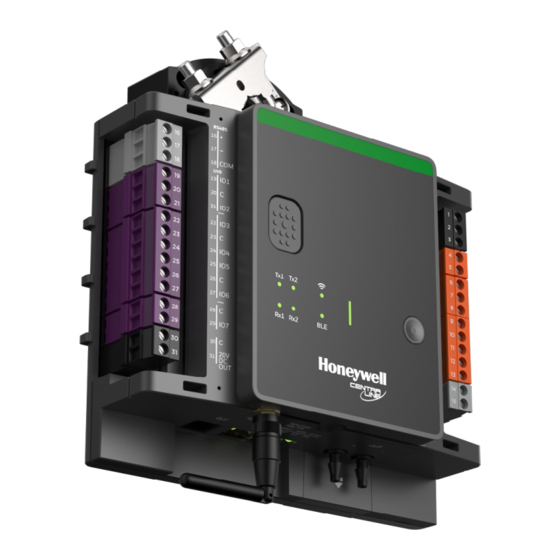
Product Description ....................................................... 2
Network Security .............................................................. 3
General Safety Instructions ............................................ 3
Specifications ................................................................... 4
Electrical ....................................................................... 4
Hardware ...................................................................... 4
Communication ............................................................. 4
Airflow Sensor ............................................................... 4
Integrator Actuator ........................................................ 4
Operational Environment .............................................. 4
Sylk™ Devices Supported ............................................ 4
Solid State Relay .......................................................... 5
Standards and Compliances ......................................... 5
Wireless Connectivity .................................................... 5
Interface ............................................................................ 5
IP Variant ...................................................................... 5
MS/TP Variant ............................................................... 6
Internal Wiring .................................................................. 6
Controller Terminals ...................................................... 7
Mounting ........................................................................... 8
Mounting Actuator onto Damper Shaft .......................... 9
Differential Pressure Sensor ......................................... 10
Airflow Sensor Replacement ......................................... 11
Wiring ................................................................................ 12
Power supply .................................................................... 14
General Information ...................................................... 14
Power Wiring ................................................................. 14
Communication ................................................................ 17
® U.S. Registered Trademark
Copyright © 2021 Honeywell Inc. • All Rights Reserved
INSTALLATION
INSTRUCTIONS
BACnet MS/TP VARIANT ................................................. 17
Antenna ........................................................................ 19
Sylk Bus™ ........................................................................ 20
Modbus ............................................................................. 21
Wiring Topology ............................................................ 21
Modbus Master Specifications ...................................... 21
BACnet IP .......................................................................... 23
Connecting to a IP network ........................................... 23
Static IP Configuration .................................................. 23
Network Topologies ...................................................... 23
Commissioning ................................................................ 24
Automatic MAC Addressing .......................................... 24
Service Button .............................................................. 25
Operator interface LEDs ............................................... 26
Regulatory Information .................................................... 27
FCC Regulation ............................................................ 27
Canadian Regulatory Statement ................................... 27
Approvals and Certifications ......................................... 28
Appendix ........................................................................... 29
Sensor Input Accuracy .................................................. 29
Recognition of Sensor Failure of Sensor Inputs ........... 29
Sensor Characteristics .................................................... 29
PT1000 ......................................................................... 30
PT3000 ......................................................................... 33
NTC10K TYPE II ........................................................... 33
NTC10K TYPE III .......................................................... 34
PT100 ........................................................................... 34
JOHNSON A99 ............................................................. 35
NTC20K ........................................................................ 35
10K3A1 ......................................................................... 37
Nickel Class B DIN 43760 sensors ............................... 38
NI1000TK5000 .............................................................. 39
Related Technical Literature ........................................... 40
EN1Z-1076GE51 R1021
Advertisement
Table of Contents

Subscribe to Our Youtube Channel
Related Manuals for Honeywell CENTRA LINE MERLIN N Series


Summary of Contents for Honeywell CENTRA LINE MERLIN N Series
-
Page 1: Table Of Contents
Nickel Class B DIN 43760 sensors ....... 38 General Information ............14 NI1000TK5000 .............. 39 Power Wiring ..............14 Related Technical Literature ........... 40 Communication ..............17 ® U.S. Registered Trademark EN1Z-1076GE51 R1021 Copyright © 2021 Honeywell Inc. • All Rights Reserved... -
Page 2: General
Spare part used in case, original air flow sensor gets damaged. Table 3. Mobile Application Honeywell Connect Mobile Honeywell Connect Mobile application for the VAV balancing can be downloaded from the Google application Play Store / Apple App store. CLME B 24 N Brand Identifier... -
Page 3: Network Security
MERLIN NX IP AND MST/TP VAV CONTROLLER - INSTALLATION INSTRUCTIONS DIMENSION 66 mm 2 1/2” 187 mm 7 1/4” 175 mm 7” 147 mm 197 mm 5 3/4” 7 3/4” 124 mm 4 3/4” 52 mm 2” 90 mm 3 1/2” 92 mm 3 1/2”... -
Page 4: Specifications
MERLIN NX IP AND MST/TP VAV CONTROLLER - INSTALLATION INSTRUCTIONS — : Dynamic: DHCP and LinkLocal, Static Addressing CAUTION CAUTION — : 10/100 Mbps Connection Speed Disconnect the power supply before installing the Airflow Sensor MERLIN NX IP and MSTP VAV controllers. Do not reconnect the power supply until you have completed Range: ±2.0 in. -
Page 5: Solid State Relay
MERLIN NX IP AND MST/TP VAV CONTROLLER - INSTALLATION INSTRUCTIONS Standards and Compliances Common terminal shared by 2 UIO, protected against 24VAC mis-wiring and short circuit UL60730, CE, UL916 Energy Management Equipment, FCC Part 15; Class A verified, EN 55022; Class A, EN Solid State Relay 61000-3-2, 61000 SSR does switch supply voltage, works with AC and DC,... -
Page 6: Ms/Tp Variant
MERLIN NX IP AND MST/TP VAV CONTROLLER - INSTALLATION INSTRUCTIONS MS/TP Variant DECLUTCH BUTTON RS485 MODBUS MODULES RS485 INTERNAL WIRING NOTE: For BACnet MS/TP variant, terminal 34 (COM), is internally connected to C (connections in green above) and COM terminals (connections in blue above). Fig. -
Page 7: Controller Terminals
MERLIN NX IP AND MST/TP VAV CONTROLLER - INSTALLATION INSTRUCTIONS Controller Terminals All the terminals for this controller are removable. Table 5. Controller Terminals Type Legend Printing Description Earth Ground (Connected to power earth ground) Ground Power Power supply voltage (Connected to 24VAC~) AC OUT 24VAC~ output SR IN... -
Page 8: Mounting
MERLIN NX IP AND MST/TP VAV CONTROLLER - INSTALLATION INSTRUCTIONS Table 5. Controller Terminals (Continued) Type Legend Printing Description IP ethernet RJ45-1/RJ45-2 Terminal 32,33, and 34 are available in MSTP variant only. Terminal for IP variant only. MOUNTING To mount the MERLIN NX IP and MSTP VAV controllers refer the mounting instructions provided with the controller. -
Page 9: Mounting Actuator Onto Damper Shaft
MERLIN NX IP AND MST/TP VAV CONTROLLER - INSTALLATION INSTRUCTIONS Tools Required: Determine the damper ‘full opening angle’ (45, 60, or 90 degrees). In the damper is open to its fully Fig. 5 — Phillips #2 screwdriver for end-limit set screw adjust- open position of 90 degrees. -
Page 10: Differential Pressure Sensor
MERLIN NX IP AND MST/TP VAV CONTROLLER - INSTALLATION INSTRUCTIONS a. Manually open the damper fully (rotate clockwise). b. The actuator is shipped with the mechanical end limits NOTE: set at 95 degrees. Adjust the two mechanical end-limit The pressure sensor is polarity sensitive. Connect set screws to provide the desired amount of rotation. -
Page 11: Airflow Sensor Replacement
MERLIN NX IP AND MST/TP VAV CONTROLLER - INSTALLATION INSTRUCTIONS Airflow Sensor Replacement NOTICE Dust particle contamination may be present in some Procedure to replace the airflow sensor is as follows: applications. Ensure appropriate measures are taken to minimize the effect of particulate contamination. Gently pull the sensor cover outward and rotate it by 75 degree. -
Page 12: Wiring
MERLIN NX IP AND MST/TP VAV CONTROLLER - INSTALLATION INSTRUCTIONS WIRING Output Connection Example 7 x Universal Input/Output (UIO) Output Type Load 0 to 10 Vdc, 10 mA max. IN 0V 4 to 20 mA 0V IN 0V IN -Voltage output to power external relay -Protective Diode is recommeded to protect the output Ensure correct... - Page 13 MERLIN NX IP AND MST/TP VAV CONTROLLER - INSTALLATION INSTRUCTIONS 1 x 20V DC Auxiliary Power Output White Black Fig. 13. 20 VDC Auxiliary wiring 5 x Solid State Relay (SSR) SR IN (terminal 5, SSR POWER input) is connected to AC OUT (terminal 4, 24V AC~ output) by a jumper wire at factory.
-
Page 14: Power Supply
MERLIN NX IP AND MST/TP VAV CONTROLLER - INSTALLATION INSTRUCTIONS POWER SUPPLY Power Wiring All wiring must comply with applicable electrical codes and General Information ordinances, or as specified on installation wiring diagrams. Controller wiring is terminated to the screw terminal blocks To prevent a risk of injury due to electrical shock and/or located on the device. - Page 15 MERLIN NX IP AND MST/TP VAV CONTROLLER - INSTALLATION INSTRUCTIONS DO NOT SWITCH ON POWER 110VAC 24 VAC /230VAC Supply voltage: 24 VAC (20 to 30 VAC) 50/60 Hz For UL rating the Important: Where multiple devices are powered from transformer must be class 2 rated.
- Page 16 MERLIN NX IP AND MST/TP VAV CONTROLLER - INSTALLATION INSTRUCTIONS The RS485 Standard Wiring Method According to the RS485 standard (TIA/EIA 485: “Electrical Characteristics of Generators and Receivers for Use in Balanced Digital Multipoint Systems”), only one driver NOTE: communicating via an RS485 interface may transmit data at When attaching two or more wires to the same termi- a time.
-
Page 17: Communication
MERLIN NX IP AND MST/TP VAV CONTROLLER - INSTALLATION INSTRUCTIONS COMMUNICATION 1. Find an unused MAC address on the MS/TP network to which the MERLIN NX MS/TP VAV controller connects. 2. Locate the DIP switch bank on the MERLIN NX MS/TP VAV BACNET MS/TP VARIANT controller BACnet for addressing. - Page 18 MERLIN NX IP AND MST/TP VAV CONTROLLER - INSTALLATION INSTRUCTIONS Shied Termination BACnet MS/TP Limitataions Following proper MS/TP cabling shield grounding There are two limitations regarding the number of procedures is important to minimize the risk of controllers per BACnet MS/TP channel: communication problems and equipment damage caused PHYSICAL LIMITATION: by capacitive coupling.
-
Page 19: Antenna
MERLIN NX IP AND MST/TP VAV CONTROLLER - INSTALLATION INSTRUCTIONS Wiring Topology Tighten the wire terminal nut by turning the nut clock- wise. Do not over-tighten. Only daisy-chain wiring topology is allowed. Other wiring topologies (such as, star wiring, mixed star wiring, and daisy chain wiring) are prohibited. -
Page 20: Sylk Bus
MERLIN NX IP AND MST/TP VAV CONTROLLER - INSTALLATION INSTRUCTIONS • Do not install the antenna close to the floor. NOTE: CLCMTR70 Wall Modules are not supported. Table 11. Recommended max. distances from controller to TR40x/T42x wall modules Standard non-twisted thermostat wire Single twisted pair, Non-Shielded, shielded or Non-... -
Page 21: Modbus
RS485 Repeaters Baudrate 19200 RS485 repeaters are possible but have not been tested by Parity Even parity Honeywell. Therefore it is the responsibility of the installing Bytesize 8 bit / commissioning person to ensure proper function. Stopbits 1 stop bit NOTE: Each Modbus segment will require its own line polarization and line termination. - Page 22 MERLIN NX IP AND MST/TP VAV CONTROLLER - INSTALLATION INSTRUCTIONS — Ground noise should not exceed the EIA-485 com- — Should not extend beyond a single building. mon mode voltage limit. — It is recommended that you select a low baud rate —...
-
Page 23: Bacnet Ip
MERLIN NX IP AND MST/TP VAV CONTROLLER - INSTALLATION INSTRUCTIONS BACNET IP Refer IRM Engineering Tool User Guide for more information on how to do this. Table 12. Default IP Address Network Topologies Static IP Address 192.168.0.2 — Recommended cable: Cat5/Cat6 Subnet Mask 255.255.255.0 —... -
Page 24: Commissioning
MERLIN NX IP AND MST/TP VAV CONTROLLER - INSTALLATION INSTRUCTIONS COMMISSIONING with, for example, 35 BACnet MSTP VAV controllers, all of the other BACnet MSTP VAV controllers will be found. Following properties are writable and can be changed: Automatic MAC Addressing —... -
Page 25: Service Button
MERLIN NX IP AND MST/TP VAV CONTROLLER - INSTALLATION INSTRUCTIONS Service Button Pressing Service Button during Power-Up If the service pin is pressed and then the controller is switched on (while the service pin is still pressed), a reset to factory delivery is performed. -
Page 26: Operator Interface Leds
MERLIN NX IP AND MST/TP VAV CONTROLLER - INSTALLATION INSTRUCTIONS Operator interface LEDs The controller features the following LEDs: BACnet MODBUS STATUS Tx &Rx Tx &Rx Fig. 31. LED interface Table 13. Status LED behaviors Mode LED Status Visual Firmware download Green blinks every 200 ms No application** Red/Green/Yellow blinks every 1 sec... -
Page 27: Regulatory Information
MERLIN NX IP AND MST/TP VAV CONTROLLER - INSTALLATION INSTRUCTIONS REGULATORY INFORMATION (1) l'appareil ne doit pas produire de brouillage, et (2) l'utilisateur de l'appareil doit accepter tout brouillage radioelectrique subi, meme si le brouillage est susceptible FCC Regulation d'en compromettre le fonctionnement. This device complies with Part 15 of the FCC Rules. -
Page 28: Approvals And Certifications
Table 16. Certification Numbers Concerning the Registration, Evaluation, Authorization and FCC ID IC ID Restriction of Chemicals (REACH) CLMEVA75MB24NM Honeywell takes compliance with REACH very seriously. CLMEVA00MB24NM 2ARTN-00005 24552-00005 According to Article 33 “Duty to communicate information CLMEVA00IB24NM on substances in articles”: CLMEVA75IB24NM —... -
Page 29: Appendix
MERLIN NX IP AND MST/TP VAV CONTROLLER - INSTALLATION INSTRUCTIONS APPENDIX Recognition of Sensor Failure of Sensor Inputs Sensor Input Accuracy The thresholds at which sensor failures – i.e., sensor The controller's internal sensor inputs support both breaks (SB) and short-circuits (SC) – are recognized NTC10K Ω... -
Page 30: Pt1000
MERLIN NX IP AND MST/TP VAV CONTROLLER - INSTALLATION INSTRUCTIONS PT1000 Terminal Terminal Terminal Temp. Temp Resistanc Temp. Temp Resistanc Temp. Temp Resistanc voltage voltage voltage [°F] .[°C] e [KΩ] [°F] .[°C] e [KΩ] [°F] .[°C] e [KΩ] Terminal Temp. Temp Resistanc 0.372... - Page 31 MERLIN NX IP AND MST/TP VAV CONTROLLER - INSTALLATION INSTRUCTIONS Terminal Terminal Terminal Terminal Temp. Temp Resistanc Temp. Temp Resistanc Temp. Temp Resistanc Temp. Temp Resistanc voltage voltage voltage voltage [°F] .[°C] e [KΩ] [°F] .[°C] e [KΩ] [°F] .[°C] e [KΩ] [°F] .[°C]...
- Page 32 MERLIN NX IP AND MST/TP VAV CONTROLLER - INSTALLATION INSTRUCTIONS Terminal Terminal Terminal Temp. Temp Resistanc Temp. Temp Resistanc Temp. Temp Resistanc voltage voltage voltage [°F] .[°C] e [KΩ] [°F] .[°C] e [KΩ] [°F] .[°C] e [KΩ] 543.2 284 2063 0.765 618.8 326 2212 0.816...
-
Page 33: Pt3000
MERLIN NX IP AND MST/TP VAV CONTROLLER - INSTALLATION INSTRUCTIONS PT3000 NTC10K TYPE II Termina Termina Temp. Temp Resistanc Temp. Temp Resistanc l voltage l voltage [°F] .[°C] e [KΩ] [°F] .[°C] e [KΩ] Temp. Temp. Resistan Terminal Termina Temp. Temp Resistanc 19.898... -
Page 34: Ntc10K Type Iii
MERLIN NX IP AND MST/TP VAV CONTROLLER - INSTALLATION INSTRUCTIONS NTC10K TYPE III PT100 Termina Temp. Resistance Temp. Temp Resistanc Temp.[°C] l voltage [°F] [Ω] [°F] .[°C] e [KΩ] 76.7 1614 Temp. Resistance Temp.[°C Resistance Temp.[°C] Temp. [°F] 201.2 94 0.813 0.315 [°F]... -
Page 35: Johnson A99
MERLIN NX IP AND MST/TP VAV CONTROLLER - INSTALLATION INSTRUCTIONS JOHNSON A99 NTC20K Termina Termina Temp. Temp Resistan Temp. Temp Resistan l voltage l voltage [°F] .[°C] ce [KΩ] [°F] .[°C] ce [KΩ] Resistanc Termina Temp. [°F] Temp.[°C] Temp. Temp Resistan 7.53 89.6... - Page 36 MERLIN NX IP AND MST/TP VAV CONTROLLER - INSTALLATION INSTRUCTIONS Termina Termina Temp. Temp Resistan Temp. Temp Resistan l voltage l voltage [°F] .[°C] ce [KΩ] [°F] .[°C] ce [KΩ] 165.2 2.68 0.96 240.8 116 0.68 0.266 2.58 0.929 242.6 117 0.66 0.259 168.8...
-
Page 37: 10K3A1
MERLIN NX IP AND MST/TP VAV CONTROLLER - INSTALLATION INSTRUCTIONS 10K3A1 Temp. Resistanc Temp. Resistanc Temp. Resistanc Temp.[°C] Temp.[°C] Temp.[°C] [°F] e [Ω] [°F] e [Ω] [°F] e [Ω] 33.8 31031 111.2 4542 188.6 1005 Temp. Resistanc Temp.[°C] [°F] e [Ω] 35.6 29500 4367... -
Page 38: Nickel Class B Din 43760 Sensors
MERLIN NX IP AND MST/TP VAV CONTROLLER - INSTALLATION INSTRUCTIONS Nickel Class B DIN 43760 sensors T(R) = a´+b´(1+c´R)½ +d´R5+e´R7 dT < 0.12 K (higher order equations on request) The characteristic of the nickel temperature sensor is Coefficients specified as per DIN 43760. The large Temperature Coefficient of Resistance (TCR) of the Ni-RTD, 6178 —... -
Page 39: Ni1000Tk5000
MERLIN NX IP AND MST/TP VAV CONTROLLER - INSTALLATION INSTRUCTIONS NI1000TK5000 Sensor Type Nominal Resistance Sensitivity : 1000 Ω Ni1000 TK5000 DIN B TC: 5000 ppm/K °F °C 790.88 830.84 826.8 822.78 818.76 814.75 810.75 806.76 802.78 798.8 794.84 871.69 867.57 863.45 859.34... -
Page 40: Related Technical Literature
EN1Z0990-GE51 CLCMTR40x/CLCMTR42x – Operating Guide EN2Z0990-GE51 Manufactured for and on behalf of the Connected Building Division of Honeywell Products and Solutions SARL, Z.A. La Pièce, 16, 1180 Rolle, Switzerland by its Authorized Representative: CentraLine Honeywell GmbH Subject to change without notice Böblinger Strasse 17...
Need help?
Do you have a question about the CENTRA LINE MERLIN N Series and is the answer not in the manual?
Questions and answers