Table of Contents
Advertisement
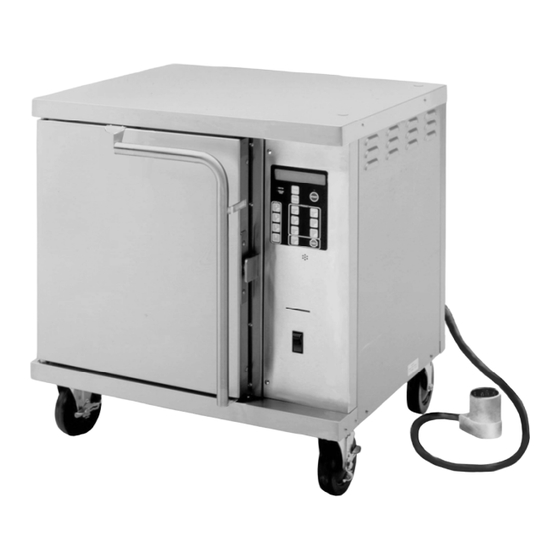
Convection Oven
Owner's Manual
Models
M42004
This manual includes material
related to installation, use,
cleaning, and care. All available
parts list[s], wiring diagrams,
or specifi cations pertaining to the unit covered by this
manual are also included.
This manual must be read and understood by all
persons using or installing this appliance. Contact
your Wells dealer if you have any questions concerning
installation, use, or maintenance of this equipment.
This manual is for the exclusive use of licensees and
employees of McDonald's Corporation as well as
employees of Wells Manufacturing.
DO NOT DISCARD THIS MANUAL.
M42004
2M-Z19624
Rev. C
02.2018
•
•
Advertisement
Table of Contents

Related Manuals for Wells M42004


Summary of Contents for Wells M42004
- Page 1 This manual must be read and understood by all persons using or installing this appliance. Contact your Wells dealer if you have any questions concerning installation, use, or maintenance of this equipment. This manual is for the exclusive use of licensees and employees of McDonald’s Corporation as well as...
- Page 2 Wells’ discretion codes, including incorrect gas or electrical connection. Wells is not...
-
Page 3: Table Of Contents
TABLE OF CONTENTS Warranty Specifications General Information Safety Information Installation Information Oven Component Overview 4–5 Cleaning 6–7 Temperature Calibration Troubleshooting Daily Operation 10–11 U.S.A. Market Menu Items 12–14 Canada Market Menu Items 208 V and 240 V Single Phase Wiring Diagram 208 V and 240 V Three Phase (Delta) Wiring Diagram 230 V Three (Wye) Phase Wiring Diagram Hinge Adjustment... -
Page 4: Specifications
Amps PLUG Weight Number (height without casters) Phase Single (Shipping) Phase 1Ø varies by M42004 30-1/8” x 27-1/4” x 25-1/8” 208V 1Ø 7500 253lbs model version 765mm x 692mm x 639mm 240V 1Ø 8400 115kg Model W x D x H Voltage &... - Page 5 fi elds ready when you call to ensure a faster service. Using any part other than genuine Wells factory supplied parts relieves the manufacturer of all liability. Due to periodic changes in designs, methods, procedures, policies, and regulations, the specifi cations contained in this document are subject to change without notice.
-
Page 6: General Information
GENERAL SAFETY INFORMATION This equipment is designed and sold for commercial use only, and is intended for use by personnel trained and experienced in its operation in order to prepare food for human consumption. This is not sold for consumer use in and around the home nor for use directly by the general public in food service locations. -
Page 7: Installation Information
GENERAL INSTALLATION INFORMATION Installation and start up should be performed by an authorized, qualified personnel only and must meet the requirements listed in this manual as well as any national and local codes. The oven will have to be mounted over a non-combustible surface such as concrete, ceramic tile, terrazzo, or metal. -
Page 8: Oven Component Overview
RIGHT REAR FRONT SIDE INTERIOR... - Page 9 COMPONENT ADDITIONAL DETAILS optional prep top optional add-on accessory that allows the top of the oven to be used as a work surface oven top covers top insulation [this panel should not be used as a work surface] oven door front oven cavity access door handle insulated handle to allow the door to be safely opened or closed...
-
Page 10: Cleaning
CLEANING DO NOT ALLOW ANY CLEANER OR LIQUID DO NOT USE COARSE SPONGES/PADS WHICH WILL SCRATCH THE FINISH. TO COLLECT ON THE TOP OF THE UNIT OR TO ENTER THE OVEN THROUGH THE VENTS DO NOT USE CAUSTIC CLEANERS, ON THE SIDE OR REAR. DEGREASERS, FLAMMABLE CLEANERS, DO NOT HOSE DOWN THE UNIT OR USE ANY OR ANY OTHER CLEANER WHICH CAN... -
Page 11: Cleaning
MONTHLY CLEANING RECOMMENDED SUPPLIES soft cloths clean water sanitizer mild detergent non-scuff scouring pad non-solvent all purpose cleaner PROCEDURE i. Use caution, as the oven will still be hot at this point. With the oven powered on, open the door. ii. -
Page 12: Temperature Calibration
TEMPERATURE CALIBRATION THIS PROCEDURE SHOULD BE PERFORMED MONTHLY BY AUTHORIZED PERSONNEL ONLY. USE CAUTION, AS THE OVEN WILL BE HOT DURING OPERATION AND MAY CAUSE SEVERE BURNS IF NOT CAREFUL. PRESSING “CANCEL” AT ANY POINT DURING THIS CALIBRATION PROCEDURE WILL BACK OUT OF THE CURRENT SCREEN AND WILL NOT SAVE OR IMPLEMENT ANY CHANGES MADE SINCE THE LAST SAVE/UPDATE. -
Page 13: Troubleshooting
TROUBLESHOOTING THIS UNIT IS NOT USER SERVICEABLE. NO PERSONNEL OTHER THAN AN AUTHORIZED TECHNICIAN SHOULD ATTEMPT TO MAKE REPAIRS OR SERVICE THIS UNIT. REMOVAL OF ANY BODY PANEL OR FUSE PRESENTS THE POSSIBILITY OF ELECTROCUTION AND SHOULD NOT BE PERFORMED WHILE THE UNIT IS CONNECTED TO ITS POWER SOURCE. THE UNIT SHOULD BE UNPLUGGED OR DISCONNECTED BEFORE ANY SERVICE IS ATTEMPTED. -
Page 14: Daily Operation
With the power supply connected, turn the power switch to the on position. The control panel will beep twice and the display will flash the Wells name. ii. By default, the “1” button will be selected when starting up the oven, meaning the oven will target the temperature and run the fan at the speed associated with the first bake stage of that product. - Page 15 COOK CYCLE i. Once the oven has come up to operating temperature, slide trays onto the appropriate rack supports. The oven is set to accommodate up to three [3] trays and to operate properly, the product trays must be set in specific locations. NUMBER OF PRODUCT TRAYS RACK POSITIONS TO USE 2 and 8...
-
Page 16: Market Menu Items
CORE MARKET [U.S.A.] PRODUCT McDONALD'S PRODUCT FACTORY DEFAULT SETTINGS SCALE FACTORS BUTTON # "DISPLAYED NAME" NUMBER OF M4200-4 FULL BISCUIT ENABLED CANCEL COOK TIME COOK TEMP COOLING TIMER COOLING TIME FACTOR VALUE TIME STAGES FAN SPEED 00000 120S BUTTON 1 00000 120S BASE TIME 5... - Page 17 SCRATCH BISCUIT MARKET [U.S.A.] PRODUCT McDONALD'S PRODUCT FACTORY DEFAULT SETTINGS SCALE FACTORS BUTTON # "DISPLAYED NAME" NUMBER OF M4200-4 FULL BISCUITS ENABLED CANCEL COOK TIME COOK TEMP COOLING TIMER COOLING TIME FACTOR VALUE TIME STAGES FAN SPEED BUTTON 00050 060S BASE TIME 00030 120S 11:30...
- Page 18 LTO [U.S.A.] PRODUCT BUTTON McDONALD'S PRODUCT FACTORY DEFAULT SETTINGS SCALE FACTORS "DISPLAYED NAME" MOZZ STICKS ENABLED CANCEL BAKE STAGES COOK TIME COOK TEMP FAN SPEED COOLING TIMER COOLING TIME FACTOR VALUE TIME 00000 120S MARKET 00000 120S BASE TIME CHOICE 05:00 375 F / 190 C HIGH...
-
Page 19: Canada Market Menu Items
NOTES... - Page 20 CORE MARKET [CANADA] BUTTON # PRODUCT “DISPLAYED NAME” MCDONALD'S PRODUCT FACTORY DEFAULT SETTINGS SCALE FACTORS BOUTON # PRODUIT “NOM AFFICHÉ” MCDONALD'S PRODUIT PARAMÈTRE D'USINE ÉLÉMENTS DE GAMME NUMBER OF FULL BISCUIT ENABLED CANCEL COOK TIME COOK TEMP FAN SPEED COOLING TIMER COOLING TIME SFACTOR VALUE...
- Page 21 NOTES...
-
Page 22: 208 V And 240 V Single Phase Wiring Diagram
WIRING DIAGRAM 208 V and 240 V single phase YEL. WHITE BLACK... -
Page 23: 208 V And 240 V Three Phase (Delta) Wiring Diagram
WIRING DIAGRAM 208 V and 240 V three phase [delta]... -
Page 24: 230 V Three (Wye) Phase Wiring Diagram
WIRING DIAGRAM 230 V three phase [wye]... -
Page 25: Hinge Adjustment
HINGE ADJUSTMENT ALLOW THE UNIT TO COOL COMPLETELY BEFORE PERFORMING ADJUSTMENT PROCEDURE. TOOLS REQUIRED i. Phillips screwdriver ii. 7/16 in. nut driver iii. 7/8 in. open end wrench iv. 1-1/8 in. open end wrench v. tape measure or other measuring device [optional] ADJUSTMENT PROCEDURE This procedure should only be performed by qualified personnel only. -
Page 26: Exploded Views
EXPLODED VIEW... -
Page 27: Exploded Views
EXPLODED VIEW... -
Page 28: Parts List
PARTS LIST REF NO PART NUMBER MODEL DESCRIPTION QTY PAGE NO F6-304607 cavity assembly (not serviceable) 2E-75309 All 208 V and 240 V 3-pole terminal block 230 V [3 Φ wye] 2E-40310 4-pole terminal block 2A-45199 blower motor spacer All 208 V and 240 V 2C-307288 solderless ground lug 230 V [3 Φ... - Page 29 REF NO PART NUMBER MODEL DESCRIPTION QTY PAGE NO M42004-2081A F6-WL0306 M42004-2401A M42004-2081B F6-WL0734 M42004-2401B M42004-2081C F6-WL0736 M42004-2401C cordset assembly M42004-2083A F6-WL0733 M42004-2403A M42004-2083B F6-WL0735 M42004-2403B M42004-2083C 2E-45177 M42004-2403C 2K-48754 All 208 V and 240 V strain relief bushing 2K-300102 230 V [3 Φ...
- Page 30 REF NO PART NUMBER MODEL DESCRIPTION QTY PAGE NO 2C-305615 latch assembly 2K-305619 upper door hinge bushing 2A-305610 door hinge pin F6-43896 bottom door hinge assembly F6-305510 rear panel F6-305511 vent coupler assembly F6-43804 lower, front trim F6-43899 door pivot plate 2C-44363 3/4-10 jam nut F6-305523...
-
Page 31: Optional Equipment Setup
OPTIONAL EQUIPMENT SETUP ALLOW THE UNIT TO COOL COMPLETELY BEFORE PERFORMING ANY SERVICE OR MAINTENANCE. MAKE CERTAIN THE OVEN IS PROPERLY SUPPORTED DURING ANY INSTALLATION WHICH REQUIRES THE OVEN TO BE RAISED OFF ITS BASE OR TO SIT ON ITS SIDE SO THE BASE MAY BE EASILY ACCESSED. SERVICE/INSTALLATION PROCEDURES SHOULD BE PERFORMED BY AUTHORIZED TECHNICIANS ONLY. - Page 32 Printed in the U.S.A. • 2M-Z19624 • Rev C • 02.2018 WELLS MANUFACTURING www.wells-mfg.com • Specifications are subject to change without notice. 265 Hobson Street Smithville, Tennessee 37166 • Telephone 888 356 5362 Fax 314 781 5445 •...
Need help?
Do you have a question about the M42004 and is the answer not in the manual?
Questions and answers