Wells OC1 Owner's Manual
Half-size
Hide thumbs
Also See for OC1:
- Operation manual (18 pages) ,
- Operation, installation, and maintenance manual (14 pages)
Advertisement
Quick Links
Download this manual
See also:
Operating Manual
273
WELLS BLOOMFIELD, LLC
10 Sunnen Dr., St. Louis, MO 63143
telephone: 888-356-5362
fax: 314-781-2714
www.wells-mfg.com
OWNERS MANUAL
HALF-SIZE
CONVECTION
OVEN
MODELS
OC1
Includes
INSTALLATION
USE & CARE
EXPLODED VIEW
PARTS LIST
WIRING DIAGRAM
OC1
IMPORTANT: DO NOT DISCARD THIS MANUAL
This manual is considered to be part of the appliance and is to be given to the OWNER or
MANAGER of the restaurant, or to the person responsible for TRAINING OPERATORS of
this appliance. Additional manuals are available from your WELLS DEALER.
THIS MANUAL MUST BE READ AND UNDERSTOOD BY ALL PERSONS USING OR
INSTALLING THIS APPLIANCE. Contact your WELLS DEALER if you have any
questions concerning installation, operation or maintenance of this equipment.
p/n
Rev. -
M273
0519
2M-Z14729
11
Advertisement

Related Manuals for Wells OC1


Summary of Contents for Wells OC1
- Page 1 Additional manuals are available from your WELLS DEALER. THIS MANUAL MUST BE READ AND UNDERSTOOD BY ALL PERSONS USING OR INSTALLING THIS APPLIANCE. Contact your WELLS DEALER if you have any questions concerning installation, operation or maintenance of this equipment.
- Page 2 Seller’s obligation under this warranty is limited warranted against defects in materials and workmanship to the repair of defects without charge by a Wells Bloomfield for a period of one year from the date of original installation factory authorized service agency or one of its sub-service or 18 months from the date of shipment from our factory, agencies.
-
Page 3: Table Of Contents
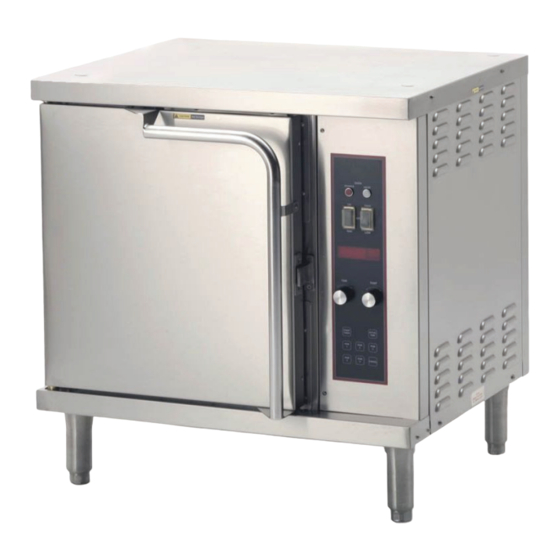
PARTS & SERVICE CUSTOMER SERVICE DATA INTRODUCTION Thank You for purchasing this Wells Bloomfield appliance. Proper installation, professional operation and consistent maintenance of this appliance will ensure that it gives you the very best performance and a long, economical service life. - Page 4 FEATURES & OPERATING CONTROLS PREP TOP OVEN DOOR (OPTIONAL) LATCH VIEWING RIGHT SIDE WINDOW ACCESS PANEL FRONT RIGHT SIDE ADJUSTABLE LEGS POWER CORD CONTROL PANEL POWER INDICATOR HEAT INDICATOR HEATING ELEMENTS RACK SUPPORTS ON-OFF-FAN SWITCH BLOWER POWER ON HEAT ON HIGH FAN HIGH-LOW INSIDE...
- Page 5 FEATURES & OPERATING CONTROLS (continued) FEATURES & OPERATING CONTROLS CAUTION: OVEN POWER SWITCH (ON-OFF-FAN): HOT SURFACE ON position (with door closed). POWER ON indicator will glow, Exposed surfaces can be hot blower fan will come on and unit will start to heat. to the touch and may cause NOTE: In the ON position, if the door is opened, blower fan is burns.
- Page 6 DO NOT connect or operate this appliance if the keypad section of the control panel is torn energize this appliance or broken. Call your Authorized Wells Service Agent for service. until all installation The technical content of this manual, including any wiring diagrams,...
-
Page 7: Specifications
INSTALLATION NOTE: DO NOT discard UNPACKING & INSPECTION the carton or other packing Carefully remove the appliance from the carton. Remove all protective materials until you have plastic film, packing materials and accessories from the appliance inspected the appliance for before connecting electrical power or otherwise performing any hidden damage and tested it installation procedure. - Page 8 INSTALLATION (continued) WARNING: EQUIPMENT SET-UP ELECTRIC 1. IF CONVECTION OVEN IS TO BE USED FOR PROTEINS, SHOCK HAZARD INSTALL EXTERNAL DUCT a. Remove two screws at each end of adapter plate on back of All servicing requiring access oven. to non-insulated electrical components must be performed b.
- Page 9 INSTALLATION (continued) DANGER: ELECTRICAL SHOCK HAZARD ELECTRICAL CONNECTIONS MUST BE MADE BY A LICENSED ELECTRICIAN Electrical shock will cause death or serious injury. CAUTION: ELECTRICAL INSTALLATION Refer to the nameplate on the front of the appliance. RISK OF • Verify the ELECTRICAL SERVICE POWER. DAMAGE •...
- Page 10 OPERATION MANUAL COOK MODE CAUTION: On ovens equipped with optional casters, be sure casters are locked HOT SURFACE before turning power switch ON. Exposed surfaces can be hot Configure oven racks as appropriate. Close the oven door. to the touch and may cause Press oven power switch to ON.
- Page 11 OPERATION (continued) PROGRAM COOK MODE CAUTION: Five programmable (PGM) keys are provided to allow presetting times HOT SURFACE and temperatures for commonly cooked menu items: Exposed surfaces can be hot 1. Press and hold the appropriate PGM key and turn the TEMP to the touch and may cause knob to the desired set temperature.
- Page 12 SUGGESTED TIMES & TEMPERATURES FOR BAKING AND ROASTING SUGGESTED TIMES & TEMPERATURES FOR BAKING AND ROASTING TEMP PRODUCT TIME (MINUTES) NO. OF RACKS °F °C BREAD PRODUCTS Hamburger Rolls Bread— 1 pound loaves 3 (12 loaves) Rolls 5 (60 rolls) Baking Soda Biscuits Pizza PASTRIES...
-
Page 13: Cleaning Instructions
CLEANING INSTRUCTIONS Allow oven to cool to 150ºF or less PREPARATION CAUTION: Daily FREQUENCY ELECTRIC SHOCK Fiber Brush, Plastic Scouring Pad, Plastic Scraper HAZARD TOOLS Disconnect appliance Mild Detergent, Conventional Oven Cleaner, Non-Abrasive Cleanser from electric power before cleaning. Clean Soft Cloth / Sponge Solution: 4 parts vinegar to 10 parts warm water CAUTION: CLEANING... -
Page 14: Troubleshooting Suggestions
Service Agency for repairs Door pops open during cook Latch out of adjustment Adjust latch cycle NOTE: There are no user serviceable components in the appliance. In all cases of damage or component malfunction, contact your Authorized Wells Service Agency for repairs. -
Page 15: Preventative Maintenance
PREVENTATIVE MAINTENANCE HINGE ADJUSTMENT CAUTION: None BURN HAZARD PRECAUTIONS: Monthly, at a Minimum; or, As Needed FREQUENCY: Allow appliance to cool Phillips (+) Screwdriver TOOLS: completely before adjusting. 7/16” Nut Driver 7/8” and 1-1/8” Wrenches THE FOLLOWING PROCEDURE IS TO BE PERFORMED BY QUALIFIED PERSONNEL ONLY Remove bottom panel to access pivot. -
Page 16: Exploded View & Parts List
EXPLODED VIEW & PARTS LIST OC1 CABINET COMPONENTS Model: OC1, Cabinet Components IL2262, Rev. -... - Page 17 EXPLODED VIEW & PARTS LIST OC1 ELECTRICAL COMPONENTS Model OC1; Cabinet Components Fig No Part No Description F6-45647 SHIELD PROX SWITCH ASSY O F6-43787 BRKT SWITCH PROXIMITY F6-43804 TRIM FR LOWER F6-43899 PLATE DOOR PIVOT 5F-21372 CASTER SWVL W/BRAKE SET OF 2...
- Page 18 EXPLODED VIEW & PARTS LIST OC1 ELECTRICAL COMPONENTS BACK OF UNIT Model: OC1, Electrical Components SOME ITEMSS ARE INCLUDED FOR ILLUSTRATION PURPOSES IL2261, Rev. - ONLY AND IN CERTAIN INSTANCES MAY DIFFER FROM ACTUAL APPEARANCE OR MAY NOT BE AVAILABLE.
- Page 19 EXPLODED VIEW & PARTS LIST OC1 ELECTRICAL COMPONENTS Model OC1; Electrical Components Fig No Part No Description Application 2T-45180 THERMO SNAP DISC 2J-304712 PROBE TEMP OC-1 F6-43837 COVER GASKET ELEM OUTER M 2I-43834 GASKET ELEM M4200 2E-34769 FUSEHLDR HPG-EE 10A 240V...
- Page 20 EXPLODED VIEW & PARTS LIST OC1 REMOVABLE COMPONENTS Model: OC1, Removable Components IL2263, Rev. - Model OC1; Removable Components Fig No. Part No Description 2B-50200-34 RACK HALF SIZE OVENS 2B-43785 SUPPORT RACK OVEN M4200 F6-43889 CLIP SUPPORT RACK M4200...
-
Page 21: Wiring Diagram
WIRING DIAGRAM... - Page 22 WIRING DIAGRAM...
-
Page 23: Parts & Service
OVEN RACK Replacement 5F-21376 or to order factory authorized replacement parts, contact PREP TOP KIT 5F-21445 your Wells authorized service agency, or call: LEGS, 6” Stainless Steel (Set of 4 legs) 2A-22226 Wells Bloomfield, LLC 10 Sunnen Dr., St. Louis MO 63143 USA Service Dept. - Page 24 WELLS BLOOMFIELD, LLC 10 Sunnen Dr., St. Louis, MO 63143 telephone: 888-356-5362 fax: 314-781-2714 www.wells-mfg.com...
Need help?
Do you have a question about the OC1 and is the answer not in the manual?
Questions and answers