Table of Contents
Advertisement
This manual is considered to be part of the oven and is to be given to the owner or
manager of the restaurant, or to the person responsible for training operators of the
oven. Additional manuals are available from your Wells Dealer.
THIS MANUAL MUST BE READ AND UNDERSTOOD BY ALL
Contact your Wells Dealer if you have any questions concerning installation, operation
maintenance or servicing of this equipment.
This manual is for the exclusive use of licensees and employees of McDonalds Systems, Inc.
p/n 45633 Rev. A
IMPORTANT: DO NOT DISCARD THIS MANUAL
PERSONS USING OR INSTALLING THIS OVEN.
WELLS MANUFACTURING COMPANY
2 ERIK CIRCLE, P. O. Box 280
Verdi, NV 89439
Customer Service (775) 345-0444 Ext.502
fax: (775) 345-0569
www.wellsbloomfield.com
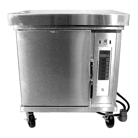
CONVECTION
903
M4200
OVEN
OWNER'S
MANUAL
OPERATING
INSTRUCTIONS
***
MAINTENANCE
INSTRUCTIONS
***
PARTS LIST
M903 081100 cps
Advertisement
Table of Contents

Related Manuals for Wells M4200


Summary of Contents for Wells M4200
- Page 1 THIS MANUAL MUST BE READ AND UNDERSTOOD BY ALL PERSONS USING OR INSTALLING THIS OVEN. Contact your Wells Dealer if you have any questions concerning installation, operation maintenance or servicing of this equipment. This manual is for the exclusive use of licensees and employees of McDonalds Systems, Inc.
- Page 2 Be sure to retain the container for inspection. Wells Manufacturing cannot assume liability for damage or loss incurred in transit. We will, however, at your request, supply you with the necessary documents to support your claim.
-
Page 3: Table Of Contents
TABLE OF CONTENTS Warranty ............. Inside Cover Specifications ............Features & Operating Controls ....... 2 Safety Procedures ..........4 Installation ............... 5 Operation ..............Preventative Maintenance Cleaning Instructions ......... 11 Latch Adjustment ..........13 Hinge Adjustment ..........15 Troubles Shooting Suggestions ......17 Exploded View / Parts List ........ -
Page 4: Features & Operating Controls
FEATURES AND OPERATING CONTROLS RIGHT REAR FRONT SIDE INSIDE OVEN... - Page 5 ITEM DESCRIPTION FUNCTION OPTIONAL PREP TOP Allows top of oven to be used as a work surface OVEN TOP Covers and protects top insulation OVEN DOOR Covers and provides access to oven cavity LATCH Holds oven door closed ACCESS PANEL Covers and provides access to fan motor and electric connections and controls COOLING LOUVERS...
-
Page 6: Safety Procedures
SAFETY PROCEDURES Knowledge of proper procedures is essential to the safe operation of electrically energized equipment. In accordance with generally accepted product safety labeling guidelines for potential hazards, the following signal words and symbols are used throughout this manual. DANGER - Danger is used to indicate the presence of a hazard which will cause DANGER severe personal injury, death, or substantial property damage in the event the state-... -
Page 7: Installation
INSTALLATION INSTRUCTIONS UNPACKING AND INSPECTION 1. Carefully remove equipment from the carton. Remove all protective plastic film and packaging materials. Remove accessories from the OVEN CAVITY before connecting electrical power or otherwise performing any installation procedures. NOTE: DO NOT discard the CARTON and other PACKAGING MATERIAL until you have inspected the appliance for hidden damage and tested it for PROPER OPERATION. -
Page 8: Curb Or Counter Mounting
EQUIPMENT SET-UP CURB or COUNTER MOUNTING Setup the appliance only on a firm, level, non-combustable surface. Verify local codes for requirements. Concrete, tile, terrazzo or metal surfaces are recommended. Metal over combustible material may not meet code for non-combustible surfaces. Appliance is approved for installation with zero clearance at bottom. -
Page 9: Operation
ELECTRICAL INSTALLATION DANGER ELECTRICAL SHOCK HAZARD ELECTRICAL CONNECTIONS MUST BE MADE BY A LICENSED ELECTRICIAN Electrical shock will cause death or serious injury. Refer to the nameplate on the front of the appliance. Verify the ELECTRICAL SERVICE POWER. Voltage and phase must match the nameplate specifications, and available electrical service amperage must meet or exceed the specifications listed on page 1. -
Page 10: Operation
OPERATION A. SET TEMPERATURE 1. Make sure the power cord is plugged into the appropriate power supply receptacle. 2. Place the ON/OFF/FAN switch in the ON position. NOTE: No display will be present until the TEMP button is pressed. 3. Press the the TEMP button momentarily to display the current oven temperature. -
Page 11: Operation
C. DAILY SET-UP PROCEDURES 1. Make sure the power cord is plugged into the appropriate USE THESE power supply receptacle. RACK 2. Recommended shelf positions for quality baked products: POSITIONS NO. OF PANS RACK POSITION OF PRODUCT UTILIZED 2 & 8 2, 5 &... -
Page 12: Operation
SUGGESTED COOKING TIMES TEMP TIME NUMBER PRODUCT ºF MINUTES OF RACKS BREAD PRODUCTS Hamburger Roll Bread (1 lb loaves) 3 (12 loaves) Roll 5 (60 rolls) Baking Soda Biscuit For best baking results, use rack positions 2, 5 & 8 ( where rack position 1 is the top rack) Baking one pan: use rack 5;... -
Page 13: Preventative Maintenance Cleaning Instructions
PM 903.1 PREVENTATIVE MAINTENANCE CLEANING INSTRUCTIONS CONVECTION OVEN M4200 PREPARATIONS: Allow oven to cool to 150ºF or less FREQUENCY: Daily TOOLS: Fiber Brush Plastic Scouring Pad, Plastic Scraper Mild Detergent, Conventional Oven Cleaner, Non-Abrasive Cleanser Clean Soft Cloth / Sponge... - Page 14 PM 903.1 PREVENTATIVE MAINTENANCE CLEANING INSTRUCTIONS CONVECTION OVEN M4200 Reinstall the fan baffle, paying particular attention that the lip on the right side of the fan baffle is fully seated in the slot in the edge of the oven cavity.
-
Page 15: Latch Adjustment
PM 903.2 PREVENTATIVE MAINTENANCE LATCH ADJUSTMENT CONVECTION OVEN M4200 PRECAUTIONS: None FREQUENCY: Monthly, at a Minimum; or, As Needed TOOLS: Phillips (+) Screwdriver, 4"x2" Strip of 20# Paper TO BE PERFORMED BY QUALIFIED PERSONEL ONLY 1. The door latch must be adjusted such that the door will latch easily, yet remain closed and latched throughout the cook cycle. - Page 16 PM 903.2...
-
Page 17: Hinge Adjustment
PM 903.3 PREVENTATIVE MAINTENANCE HINGE ADJUSTMENT CONVECTION OVEN M4200 PRECAUTIONS: None FREQUENCY: Monthly, at a Minimum; or, As Needed TOOLS: Phillips (+) Screwdriver, 4"x2" Strip of 20# Paper 7/16" Nut Driver, 7/8" and 1-1/8" Wrenches TO BE PERFORMED BY QUALIFIED PERSONEL ONLY... - Page 18 PM 903.3 PREVENTATIVE MAINTENANCE CARD HINGE ADJUSTMENT CONVECTION OVEN M4200 3. The door should be approximately centered between the upper and lower lips of the cabinet. Adjust the door for height: a. The hinge sleeve acts as a jam nut for the height adjuster.
-
Page 19: Troubles Shooting Suggestions
Blown fuse(s) (item L): Correct cause of over-current and replace fuses with fuses having the same configuration and ratings. Possible internal component damage: Have unit serviced by an Authorized Wells Service Agency. CONVECTION OVEN FAN WILL NOT RUN Verify that the oven switch is set to ON or FAN. -
Page 20: Exploded View / Parts List
EXPLODED VIEW 4pl. M4200 Cabinet & Related Components ref. ref. ref. 69 g 4 pl. 2 pl. 4 pl. 2 pl. - Page 21 M4200 Parts List Cabinet & Related Components item description svc p/n ASSY, CAVITY PANEL, CONTROL 69763 BRACKET, MOTOR MOUNT BRACKET, CAVITY SUPPORT GROMMET, 7/8" O.D. 51040 INSULATION, TOP & BOTTOM INSULATION, WRAP ASSY, BAFFLE SUPPORT MOUNT, TEMP SENSORS COVER, DOOR GASKET...
-
Page 22: Parts List Internal Components
2 pc. 3pl. M4200 h p q Internal Components ref. ref. SE E D E TAIL A SE E b c d e D E TAIL B DETAIL A C AV ITY SP AC E R p aa ref. ref. - Page 23 M4200 Parts List Internal Components item description svc p/n ASSY, CAVITY TERMINAL BLOCK, 3 POLE 50131 SPACER, BLOWER MOTOR LUG, SOLDERLESS PANEL, CONTROL 69763 MOTOR, 1/4 HP 63932 START CAPACITOR (ONLY) 69823 SPACER, MOTOR MOUNT BLOWER WHEEL 63797 BRACKET, MOTOR MOUNT...
-
Page 24: Wiring Diagram
WIRING DIAGRAM... -
Page 25: Parts & Service
2 Erik Circle, P. O. Box 280 Verdi, NV 89439 phone: (775) 345-0444 ask for Service Department fax: (888) 492-2783 Service Parts Department can supply you with the name / telephone number of the WELLS AUTHORIZED SERVICE AGENCY nearest you. ACCESSORIES PART#... - Page 26 PREPARED FOR ® WELLS MANUFACTURING COMPANY 2 ERIK CIRCLE, P. O. Box 280 Verdi, NV 89439 Customer Service (775) 345-0444 Ext. 502 fax: (775) 345-0569 www.wellsbloomfield.com...
Need help?
Do you have a question about the M4200 and is the answer not in the manual?
Questions and answers