Table of Contents
Advertisement
Quick Links
509
WELLS MANUFACTURING
265 Hobson Street, Smithville, Tennessee 37166
telephone: 314-678-6314
fax: 314-781-2714
www.wells-mfg.com
OWNER'S MANUAL
WVOG136 SERIES
GRIDDLE and
CONVECTION
OVEN
with
UNIVERSAL
HOOD
MODEL:
WVOG136
OCG136
Includes
INSTALLATION
USE & CARE
EXPLODED VIEW
PARTS LIST
WIRING DIAGRAM
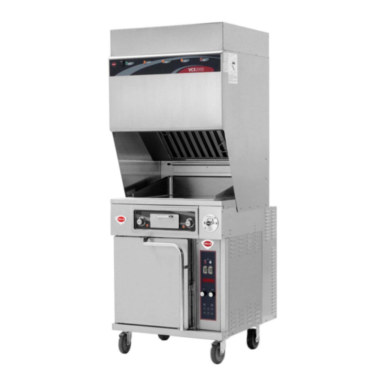
Model WVOC-G136
IMPORTANT: DO NOT DISCARD THIS MANUAL
This manual is considered to be part of the appliance and is to be given to the OWNER or
MANAGER of the restaurant, or to the person responsible for TRAINING OPERATORS of
this appliance. Additional manuals are available from your WELLS DEALER.
THIS MANUAL MUST BE READ AND UNDERSTOOD BY ALL PERSONS USING OR
INSTALLING THIS APPLIANCE. Contact your WELLS DEALER if you have any
questions concerning installation, operation or maintenance of this equipment.
04/2018
Rev. H
305936
2M-
Advertisement
Table of Contents

Related Manuals for Wells WVOG136 Series


Summary of Contents for Wells WVOG136 Series
- Page 1 Additional manuals are available from your WELLS DEALER. THIS MANUAL MUST BE READ AND UNDERSTOOD BY ALL PERSONS USING OR INSTALLING THIS APPLIANCE. Contact your WELLS DEALER if you have any questions concerning installation, operation or maintenance of this equipment.
- Page 2 Wells’ discretion have the parts replaced or codes, including incorrect gas or electrical connection. Wells is not liable repaired by Wells or a Wells-authorized service agency.
-
Page 3: Specifications
PARTS & SERVICE ............ CUSTOMER SERVICE DATA ........INTRODUCTION Thank You for purchasing this Wells Manufacturing appliance. Proper installation, professional operation and consistent maintenance of this appliance will ensure that it gives you the very best performance and a long, economical service life. -
Page 4: Features & Operating Controls
FEATURES & OPERATING CONTROLS VENTILATOR CONTROL PANEL see pages 4 & 5 GRIDDLE CONTROL PANEL see pages 4 & 5 IN CASE OF FIRE A N S U L ® PULL HANDLE T O A C T IVA T E FIR E S U P PR E S S ION S Y S T E M COCKED... - Page 5 FEATURES & OPERATING CONTROLS (continued) VENTILATOR SECTION ITEM DESCRIPTION COMMENT NAMEPLATE Lists Manufacturer, Model and Serial Number information. Also lists electrical specifications. FIRE SUPPRESSION Container for Ansulex™ Low-pH liquid fire suppression liquid. AGENT TANK (1.5 gal.) ADJUSTABLE (FRONT) Allows the unit to be leveled. RIGID (REAR) CASTER Allows the unit to be easily positioned by lifting the front of the unit slightly.
- Page 6 FEATURES & OPERATING CONTROLS (continued) Fig. 2 Ventilator Section Controls & Indicator Lights Fig. 3 Griddle & Warmer Drawer Operating Features & Controls...
- Page 7 FEATURES & OPERATING CONTROLS (continued) ITEM DESCRIPTION COMMENT VENTILATOR SECTION CONTROLS V.01 POWER SWITCH Energizes blower motor. If, after 10 seconds, proper conditions are met, appliance is energized. V.02 GREEN. Glows when POWER switch is POWER ON INDICATOR LIGHT V.03 AMBER.
-
Page 8: Precautions And General Information
PRECAUTIONS AND GENERAL INFORMATION DANGER NOTE: Fire suppression system and all associated components must only be serviced by an authorized Ansul® Distributor. All setup, ELECTRIC SHOCK HAZARD charging, repair and/or adjustment of the fire suppression system must be performed by an Authorized Ansul® Distributor ONLY. IMPORTANT: If a remote pull station is installed, both rear casters (9) must be replaced with legs to deter moving the unit. -
Page 9: Agency Listing Information
(i.e. red SERVICE REQUIRED light is on), when the user fails to have the proper replacement pre-filter and/or filter pack on hand. The Ventless Cooking System™ hood is designed as part of a WELLS cooking appliance only. No other use of this product is authorized by the manufacturer or its agents. -
Page 10: Installation
INSTALLATION NOTE: DO NOT discard UNPACKING & INSPECTION the carton or other packing materials until you have Carefully remove the appliance from the carton. Remove all inspected the appliance for protective plastic film, packing materials and accessories from the hidden damage and tested it Appliance before connecting electrical power or otherwise performing for proper operation. -
Page 11: Electrical Installation
INSTALLATION (continued) IMPORTANT! SERVICE TECHNICIAN INSTALLATION NOTES Verify that this VENTILATOR An Ansul® technician must charge and arm the fire suppression system and food cooking equipment before the ventilator blower will operate. See page 10. installation is in compliance with the specifications listed Installation and start up must be performed by an Authorized in this manual, with local Installation Company. - Page 12 (i.e. remove rear casters and replace with legs). Additional legs may be ordered through an Authorized Wells Service Agency. See page 31. 2. The FIRE SUPPRESSION SYSTEM is comprised of a pressurized cartridge &...
- Page 13 INSTALLATION (continued) NOTE: FILTERS INSTALLATION The GREASE BAFFLE and 1. FILTER PACK: Ships installed in the hood. If the FILTER PACK is FILTER PACK activate not in position, the CHECK FILTERS indicator will light. mechanical switches, and the If the FILTER PACK becomes clogged, the REPLACE FILTER PRE-FILTER activates a PACK indicator will glow.
- Page 14 INSTALLATION (continued) WARNING: GREASE TROUGH AND GREASE CUP INSTALLATION GREASE TROUGH AND GREASE CUP INSTALLATION SLIP / FALL 1. Install the GREASE TROUGH into the brackets below the grease 1. Install the GREASE COLLECTOR on the pins below the filter HAZARD baffle.
-
Page 15: Operation
OPERATION CAUTION: VENTILATOR OPERATION HOT SURFACE 1. Press the VENTILATOR POWER switch to ON. The green VENTILATOR POWER light will glow and the blower fan will start. Exposed surfaces can be hot After a short time, if all filters are sensed as being in position and to the touch and may cause not clogged, the griddle will be energized. -
Page 16: Griddle Operation
As manufactured, the steel d. Wipe the griddle surface with a clean damp cloth until all oil is surface of your Wells griddle removed. has microscopic pores. It is e. For new griddles, repeat this procedure 2-3 times until the important to fill these pores griddle has a slick, clean surface. - Page 17 OPERATION (continued) CONVECTION OVEN OPERATING INSTRUCTIONS CAUTION: HOT SURFACE A. MANUAL COOK MODE 1. Set the OVEN POWER SWITCH (C.01) to ON. The OVEN Exposed surfaces can be hot POWER ON INDICATOR (C.03) will glow when the switch is ON. to the touch and may cause 2.
- Page 18 OPERATION (continued) CAUTION: C. TEMPERATURE OFFSET MODE HOT SURFACE 1. A user preference offset mode is provided should the user feel the oven cooks too hot or too cold. Exposed surfaces can be hot 2. The OFFSET MODE can be used to offset the set / displayed to the touch and may cause temperature from the sensed temperature by as much as ±...
-
Page 19: Suggested Cooking Times
OPERATION (continued) SUGGESTED COOKING TIMES CONVECTION OVEN PRODUCT TEMP TIME NUMBER ºF MINUTES OF RACKS BREAD PRODUCTS Hamburger Roll Bread (1 lb loaves) 3 (12 loaves) Roll 5 (60 rolls) Baking Soda Biscuit For best baking results, use rack positions 2, 5 & 8 ( where rack position 1 is the top rack) Baking one pan: use rack 5;... -
Page 20: Cleaning Instructions
CLEANING INSTRUCTIONS CONVECTION OVEN CLEANING INSTRUCTIONS DANGER ELECTRIC SHOCK HAZARD PRECAUTIONS Turn oven power switch to FAN Allow oven to cool FREQUENCY As Noted TOOLS Mild Detergent, Soft Cloth or Sponge Plastic Scouring Pad Spray Bottle Commercial Oven Cleaner/Degreaser DAILY 1. - Page 21 CLEANING INSTRUCTIONS (continued) GRIDDLE DAILY CLEANING CAUTION: ELECTRIC PREPARATIONS: Set temperature control to 225ºF. Allow the SHOCK HAZARD griddle temperature to drop to 225ºF before proceeding. Disconnect appliance from FREQUENCY: Daily electric power before cleaning. TOOLS: Standard Griddle only: Griddle Brick or Pumice Stone, Fiber Brush Plastic Scouring Pad, Plastic Scraper CAUTION: Chrome-Plated Griddle only:...
- Page 22 CLEANING INSTRUCTIONS (continued) VENTILATOR WEEKLY CLEANING CAUTION: ELECTRIC PREPARATION: Disconnect appliance from electric power SHOCK HAZARD Allow to cool before cleaning Disconnect appliance from FREQUENCY: Weekly electric power before cleaning. TOOLS: Warm water and a mild detergent Soft clean cloth or sponge CAUTION: Bristle brush Container for disposal of grease...
- Page 23 CLEANING INSTRUCTIONS (continued) VENTILATOR MONTHLY CLEANING CAUTION: ELECTRIC PREPARATION: Disconnect appliance from electric power SHOCK HAZARD Allow to cool before cleaning Disconnect appliance from FREQUENCY: Monthly electric power before cleaning. TOOLS: Warm water and a mild detergent Soft clean cloth or sponge CAUTION: Plastic scouring pad, plastic scraper Container for disposal of grease...
-
Page 24: Troubleshooting Suggestions
Agency. NOTE: Other than filters, there are no user serviceable components in the appliance. A. In all cases of damage or component malfunction, contact your Authorized Wells Service Agency for repairs. B. For service of the fire suppression system, contact an Authorized Ansul® Distributor. -
Page 25: Servicing Instructions
SERVICING INSTRUCTIONS TEMPERATURE CALIBRATION CAUTION: HOT SURFACE PRECAUTIONS: The technician is exposed to hot surfaces during this procedure. Wear appropriate Exposed surfaces can be hot protective clothing. to the touch and may cause FREQUENCY: Monthly, at a Minimum; or, As Needed burns. -
Page 26: Burn Hazard
SERVICING INSTRUCTIONS (continued) CAUTION: HINGE ADJUSTMENT BURN HAZARD PRECAUTIONS: None Allow appliance FREQUENCY: Monthly, at a Minimum; or, As Needed to cool completely before adjusting. TOOLS: Phillips (+) Screwdriver 7/16" Nut Driver 7/8" and 1-1/8" Wrenches THE FOLLOWING PROCEDURE IS TO BE PERFORMED BY QUALIFIED PERSONNEL ONLY 1. -
Page 27: Maintenance Schedules
MAINTENANCE SCHEDULES USE AND MAINTENANCE 1. 6-MONTH MAINTENANCE (MUST BE PERFORMED BY AN SHALL BE IN ACCORDANCE AUTHORIZED ANSUL® DISTRIBUTOR ONLY): WITH THE STANDARD FOR VENTILATION CONTROL Inspect and test total operation including FIRE DAMPER and AND FIRE PROTECTION OF all SAFETY INTERLOCKS. -
Page 30: Section 1 - Identity
ANSUL MATERIAL SAFETY DATA SHEET ANSUL INCORPORATED ® MARINETTE, WI 54143-2542 ANSULEX Low pH QUICK IDENTIFIER (In Plant Common Name) Emergency Manufacturer’s CHEMTREC ANSUL INCORPORATED Telephone No.: Name: (800) 424-9300 or (703) 527-3887 Address: One Stanton Street, Marinette, WI 54143-2542 Other Information (715) 735-7411 Calls:... -
Page 31: Section 5 - Health Hazards
ANSULEX Low pH (continued) SECTION 5 - HEALTH HAZARDS Threshold None Established Limit Value: Routes of Entry: Irritant Eye Contact: Skin Contact: Irritant Inhalation: Not an expected route of entry. Can be irritating to mucous membranes. Ingestion: Irritating to mucous membranes. Acute Oral LD (Sprague-Dawley rats) 825.5mg/kg. Acute Exposure: Material irritates skin, eyes, and mucous membranes. -
Page 32: Exploded View And Parts List
EXPLODED VIEW & PARTS LIST HOOD SECTION - CABINET COMPONENTS INTERNAL BRACKETS LABEL, CONTROL PANEL 2M-302782 GASKET, SILICONE 15-1/4” 1P-302749 (sold by foot) GASKET, SILICONE 18-1/2” 1P-302749 (sold by foot) ASSY, FILTER PACK, M3-302775 PREFILTER 2I-302579 HOUSING, LIGHT SOCKET 2E-305098 CAGE, PRE-FILTER BULB, APPLIANCE... - Page 33 EXPLODED VIEW & PARTS LIST HOOD SECTION - ELECTRICAL & VACUUM COMPONENTS FITTING, 1/2” CONDUIT ASSY BLOWER, 240V STRAIGHT, 2K-37748X 2U-302584 #4 VACUUM SWITCH 2E-302593 #1 VACUUM SWITCH 2E-302590 #3 VACUUM SWITCH 2E-302592 ASSY VAC TUBE MANIFOLD N1-307594 #2 VACUUM SWITCH 2E-302591 ref Ansul®...
- Page 34 EXPLODED VIEW & PARTS LIST CONVECTION OVEN SECTION - CABINET COMPONENTS SUPPORT, DOOR OVEN RACK STRIKER CLIP, RACK BUSHING, TOP 2C-305616 2B-43785 SUPPORT HINGE 2K-305619 F6-43889 B I N PIN, HINGE 2A-305610 OVEN RACK 2B-50200-34 DOOR LATCH 2C-305615 ASSEMBLY DOOR COMPLETE F6-504444 GUARD, PROX.
- Page 35 EXPLODED VIEW & PARTS LIST CONVECTION OVEN SECTION - ELECTRICAL COMPONENTS CONTACTOR 208/240V ELEMENT, INNER COVER, GASKET 3ø 50a 2E-302789 2N-43872UL (208V) INNER F6-43836 2N-43783UL (240V) RELAY, BLDG FIRE ALARM 2E-44514 THERMOCOUPLE OVEN 2J-304712 ELEMENT OUTER TERMINAL BLOCK 2N-43800UL (208V) FIRE ALARM 2E-33068 63833 (240V) THERMO,...
- Page 36 EXPLODED VIEW & PARTS LIST GRIDDLE SECTION - GRIDDLE PLATE & HEATING ELEMENT COMPONENTS INSULATION PAD 57407 (pk 2'x4') COVER, GREASE DRAWER G7-31995 NUT, 1/4-20 HEX Ni 51253 (pk 100) CLAMP, THERMO CLIP, TIE-DOWN INSULATION BULB 52028 G7-33474 TUBE, THERMO BULB 18"...
- Page 37 TAPE, CORK BOX 52005 56178 (15’rl) FRONT PANEL 51025 NUT, 8-32 KEPS 51053 (pk100) SCREW, 8-32 x 2-1/2” 51734 (pk100) HANDLE 51973 SHROUD, GREASE DRAWER 51989 WELLS TRAY FRONT 53948 SCREW 6ABx5/16 53935 (pk100) GREASE TRAY ASSY COMPLETE 50279 KNOB 50259...
- Page 38 ANSUL® FIRE SUPPRESSION SYSTEM COMPONENTS FOR USE ONLY BY AUTHORIZED ANSUL© SERVICE PERSONNEL Refer to Ansul© part no. 418078-05 R-102 Restaurant Fire Suppression System Design, Installation, Recharge and Maintenance ref. NOZZLE 290 ANSUL© p/n 419342 ref. ADAPTER, QUICK-SEAL 3/8” ref. NOZZLE 1W ANSUL©...
-
Page 39: Wiring Diagram
WIRING DIAGRAM HOOD SECTION CHECK REPLACE REPLACE SERVICE FILTER PREFILTER FILTER PACK REQUIRED POWER ON EXTERNAL INDICATOR INDICATOR INDICATOR INDICATOR INDICATOR CONTROL TERMINAL BLOCK EXTERNAL VENTILATOR SHUTDOWN POWER SWITCH CONTROL JUMPER VACUUM SWITCH POWER VS4 (AIRFLOW) HOOD CORD LIGHT BLACK WHITE GREASE BAFFLE POSITION SW... - Page 40 WIRING DIAGRAM CONVECTION OVEN & GRIDDLE SECTION...
- Page 41 NOTES...
- Page 42 NOTES...
-
Page 43: Parts And Service
WELLS BULLETIN (ANSUL® PARTS LIST) DD-303331 Service Dept. NOTE: Ansul® Manual 418087-05 and phone: (314) 678-6314 Wells Bulletin 303331 are intended for use fax: (314) 781-2714 by authorized Ansul® service personnel only. Service Parts Department can Ansul® Manual 418087-05 must be obtained supply you with the name and through your authorized Ansul®... - Page 44 WELLS MANUFACTURING 265 Hobson Street, Smithville, Tennessee 37166 telephone: 314-678-6314 fax: 314-781-2714 www.wells-mfg.com...
Need help?
Do you have a question about the WVOG136 Series and is the answer not in the manual?
Questions and answers