Table of Contents
Advertisement
Quick Links
Download this manual
See also:
Owner's Manual
Model
WVOC-4HF
IMPORTANT: DO NOT DISCARD THIS MANUAL
This manual is considered to be part of the appliance and is to be given to the OWNER or
MANAGER of the restaurant, or to the person responsible for TRAINING OPERATORS of
this appliance. Additional manuals are available from your WELLS DEALER.
THIS MANUAL MUST BE READ AND UNDERSTOOD BY ALL PERSONS USING OR
INSTALLING THIS APPLIANCE. Contact your WELLS DEALER if you have any
questions concerning installation, operation or maintenance of this equipment.
304964
Rev. F
2M-
WELLS MANUFACTURING
265 Hobson Street, Smithville, Tennessee 37166
telephone: 314-678-6314
fax: 314-781-2714
www.wells-mfg.com
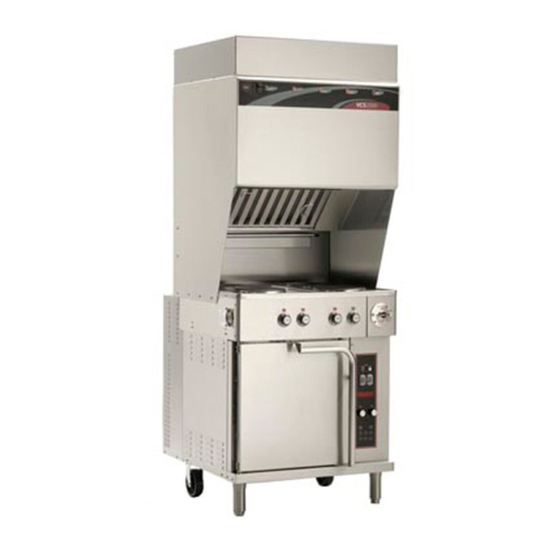
4 HOTPLATE COOKTOP
OWNER'S MANUAL
WVOC- 4 SERIES
CONVECTION OVEN
and
with
UNIVERSAL
HOOD
MODELS:
WVO4HF
WVO4HS
Includes
INSTALLATION
USE & CARE
EXPLODED VIEW
PARTS LIST
WIRING DIAGRAM
506
04/2018
Advertisement
Table of Contents

Related Manuals for Wells WVO4HF


Summary of Contents for Wells WVO4HF
- Page 1 Additional manuals are available from your WELLS DEALER. THIS MANUAL MUST BE READ AND UNDERSTOOD BY ALL PERSONS USING OR INSTALLING THIS APPLIANCE. Contact your WELLS DEALER if you have any questions concerning installation, operation or maintenance of this equipment.
- Page 2 Wells’ discretion have the parts replaced or codes, including incorrect gas or electrical connection. Wells is not liable repaired by Wells or a Wells-authorized service agency.
-
Page 3: Table Of Contents
This manual contains the information needed to properly install this appliance, and to use and care for the appliance in a manner which will ensure its optimum performance. SPECIFICATIONS AMPS 3ø MODEL VOLTS WATTS AMPS 1ø 11,500 WVO4HF 14,100 12,500 WVO4HS 16,500 Minimum clearances required from unit to nearest combustible surface or object. BACK SIDE... -
Page 4: Features & Operating Controls
FEATURES & OPERATING CONTROLS Fig. 1 Ventilator Section Features & Operating Controls... - Page 5 FEATURES & OPERATING CONTROLS (continued) VENTILATOR SECTION ITEM DESCRIPTION COMMENT Gives Manufacturer, Model and Serial Number information. NAMEPLATE FIRE SUPPRESSION AGENT TANK (1.5 gal.) ADJUSTABLE (FRONT) LEG Allows the unit to be leveled. Allows the unit to be easily positioned by lifting the front of the unit RIGID (REAR) CASTER slightly.
- Page 6 FEATURES & OPERATING CONTROLS (continued) Fig. 2 Ventilator Section Controls & Indicator Lights Fig. 3 Cooktop Section Controls & Indicator Lights Fig. 4 Convection Oven Operating Features & Controls...
- Page 7 FEATURES & OPERATING CONTROLS (continued) Item NO. Description Comments VENTILATOR SECTION CONTROLS POWER SWITCH Energizes blower motor. If, after 10 seconds, proper conditions POWER ON INDICATOR are met, cooktop is energized. CHECK FILTERS ALARM INDICATOR GREEN. Glows when POWER switch is ON. REPLACE PREFILTER ALARM INDICATOR AMBER.
-
Page 8: Precautions & General Information
PRECAUTIONS AND GENERAL INFORMATION NOTE: Fire suppression system and all associated components must only be serviced by an authorized Ansul® Distributor. All setup, DANGER ELECTRIC SHOCK HAZARD be performed by an Authorized Ansul® Distributor ONLY. IMPORTANT: If a remote pull station is installed, both rear casters (9) must be replaced with legs to deter moving the unit. -
Page 9: Agency Listing Information
(i.e. red SERVICE REQUIRED light is on), when the user fails to Fig. 5 Ventilator the manufacturer or its agents. Wells Mfg. assumes no liability for the Warning use of this equipment with products by any other manufacturer’s, or for... -
Page 10: Installation
INSTALLATION UNPACKING & INSPECTION Carefully remove the appliance from the carton. Remove all materials until you have inspected the appliance for Appliance before connecting electrical power or otherwise performing hidden damage and tested it any installation procedure. for proper operation. Carefully read all instructions in this manual and the Installation Refer to SHIPPING DAMAGE Instruction Sheet t... - Page 11 INSTALLATION (continued) SERVICE TECHNICIAN INSTALLATION NOTES IMPORTANT! Verify that this VENTILATOR before the ventilator blower will operate. See page 10. installation is in compliance Installation and start up must be performed by an Authorized Installation Company. in this manual, with local Installer must complete the WARRANTY REGISTRATION form, and code requirements, and in record appliance installation particulars on the CUSTOMER SERVICE...
- Page 12 Ansul® system to discharge. (i.e. remove rear casters and replace with legs). Additional legs may be ordered through an Authorized Wells Service Agency. See 2. The FIRE SUPPRESSION SYSTEM is comprised of a...
- Page 13 While pressing slightly against the bottom of the assembly, pull the verify proper engagement FILTER HANDLE toward you so as to engage the FILTER HOOK Use only genuine Wells GREASE BAFFLE: If the GREASE BAFFLE is not in place, the CHECK FILTERS indicator will glow.
- Page 14 INSTALLATION (continued) WARNING GREASE TROUGH AND GREASE CUP INSTALLATION AZARD PILLED OIL 2. Install the GREASE CUP on the right side of the unit, directly below the grease trough. OVEN RACK INSTALLATION the left wall of the oven cavity. DO NOT OPERATE UNLESS THE GREASE CUP IS INSTALLED.
-
Page 15: Operation
OPERATION AUTION: VENTILATOR OPERATION OT SURFACE Press the VENTILATOR POWER switch to ON. The green VENTILATOR POWER light will glow and the blower fan will start. Exposed surfaces can be hot to the touch and may cause burns. warmer is energized at all times. During normal operation, the VENTILATOR POWER light will be the only light glowing on the upper control panel. - Page 16 OPERATION (continued) SUGGESTED COOKING TIMES A. CONVECTION OVEN PRODUCT TEMP TIME NUMBER ºF MINUTES OF RACKS BREAD PRODUCTS PASTRIES OTHER NOTE: sensitive to air currents, such as meringue pie.
- Page 17 OPERATION (continued) AUTION: CONVECTION OVEN OPERATING INSTRUCTIONS OT SURFACE A. MANUAL COOK MODE xposed surfaces 1. Set the OVEN POWER SWITCH (C.01) to ON. The OVEN can be hot to the touch and POWER ON INDICATOR (C.03) will glow when the switch is ON. may cause burns.
-
Page 18: Cleaning Instructions
OPERATION (continued) AUTION: C. TEMPERATURE OFFSET MODE OT SURFACE 1. A user preference offset mode is provided should the user feel the Exposed surfaces can be hot to the touch and may cause burns. 2. The OFFSET MODE can be used to offset the set / displayed a. - Page 19 OPERATION (continued) HOTPLATE OPERATING INSTRUCTIONS AUTION: OT SURFACE COOKING WITH YOUR HOTPLATE Exposed surfaces can be hot to the touch and may cause burns. 1. Each element is individually controlled by a TEMPERATURE which control based on electrical AUTION: current draw, not the actual LECTRIC temperature of the hotplate HOCK HAZARD...
- Page 20 CLEANING INSTRUCTIONS CONVECTION OVEN CLEANING INSTRUCTIONS DANGER PRECAUTIONS Turn oven power switch to FAN ELECTRIC SHOCK HAZARD Allow oven to cool FREQUENCY Y As Noted TOOLS Mild Detergent, Soft Cloth or Sponge Plastic Scouring Pad Spray Bottle Commercial Oven Cleaner/Degreaser DO NOT SPRAY WATER ON OR AROUND DAILY ELECTRICAL EQUIPMENT...
- Page 21 CLEANING INSTRUCTIONS (continued) HOTPLATE CLEANING INSTRUCTIONS AUTION: URN HAZARD PRECAUTIONS Turn oven controls to OFF Turn off both hotplates and Allow hotplates to cool allow to cool before cleaning FREQUENCY Daily CAUTION: LECTRIC TOOLS Mild Detergent, Soft Cloth or Sponge HOCK HAZARD Non-abrasive Cleaner, Plastic Scouring Pad DO NOT splash...
- Page 22 CLEANING INSTRUCTIONS (continued) AUTION: VENTILATOR SECTION CLEANING INSTRUCTIONS LECTRIC HOCK HAZARD PREPARATION Disconnect appliance from electric power Disconnect appliance Allow to cool before cleaning from electric power before cleaning. FREQUENCY TOOLS AUTION: Warm water and a mild detergent OT SURFACE Soft clean cloth or sponge Bristle brush Exposed surfaces can be hot...
-
Page 23: Troubleshooting Suggestions
1. Verify that associated temperature control is set to the desired temperature. CONVECTION OVEN 2. Possible internal component damage: Have unit serviced by an CONTROLLER Authorized Wells Service Agency. ERROR CODES F1 Relay closed or relay C. CONVECTION OVEN WILL NOT HEAT ohms low when not 1. -
Page 24: Maintenance Instructions
MAINTENANCE INSTRUCTIONS FAN CLEANING CAUTION: ISK OF PRECAUTIONS: NJURY Allow the oven to cool. Disconnect appliance from electrical power before performing any of these FREQUENCY: procedures. TOOLS: Moist Cloth or Spongs Bristle Brush AUTION: UT HAZARD 1. Disconnect power at the Use due care when oven to cool. - Page 25 MAINTENANCE INSTRUCTIONS (continued) HINGE ADJUSTMENT AUTION: URN HAZARD PRECAUTIONS: None Allow appliance to cool FREQUENCY: completely before adjusting. TOOLS: Phillips (+) Screwdriver 7/16” Nut Driver 7/8” and 1-1/8” Wrenches THE FOLLOWING PROCEDURE IS TO BE PERFORMED BY QUALIFIED PERSONNEL ONLY 1.
- Page 26 MAINTENANCE INSTRUCTIONS (continued) D. TEMPERATURE CALIBRATION AUTION: ot Surface TOOLS: Digital Pyrometer with Oven Probe, Protective Gloves Exposed surfaces can be hot 1. With the oven empty, clamp the thermocouple sensor in the center to the touch and may cause burns.
-
Page 27: Maintenance Schedules
MAINTENANCE SCHEDULES USE AND MAINTENANCE 1. 6-MONTH MAINTENANCE (MUST BE PERFORMED BY AN SHALL BE IN ACCORDANCE AUTHORIZED ANSUL® DISTRIBUTOR ONLY): WITH THE STANDARD FOR Inspect and test total operation including FIRE DAMPER and VENTILATION CONTROL all SAFETY INTERLOCKS. AND FIRE PROTECTION OF All FIRE SUPPRESSION SYSTEM actuation components COMMERCIAL COOKING including MANUAL PULL STATION and any REMOTE... - Page 30 ANSUL ANSUL INCORPORATED MATERIAL SAFETY DATA SHEET ® ANSULEX Low pH QUICK IDENTIFIER (In Plant Common Name) Emergency Manufacturer’s CHEMTREC ANSUL INCORPORATED Telephone No.: Name: (800) 424-9300 or (703) 527-3887 Address: Other Information Calls: Prepared By: Safety and Health Department Date Prepared: February 1, 1999 SECTION 1 - IDENTITY...
- Page 31 SECTION 5 - HEALTH HAZARDS ANSULEX Low pH (continued) Threshold None Established Limit Value: Routes of Entry: Irritant Eye Contact: Irritant Inhalation: Not an expected route of entry. Can be irritating to mucous membranes. Ingestion: Signs and Symptoms: Medical Conditions Generally Aggravated by Exposure: OSHA Chemical Listed as...
- Page 32 ANSUL® FIRE SUPPRESSION SYSTEM COMPONENTS FOR USE ONLY BY AUTHORIZED ANSUL© SERVICE PERSONNEL ref. ADAPTER, QUICK-SEAL 3/8” ANSUL© p/n 77284 Refer to Ansul© part no. 418078-05 ref. NOZZLE 290 R-102 Restaurant Fire Suppression ANSUL© p/n 419342 System Design, Installation, Recharge and Maintenance ref.
-
Page 33: Exploded View & Parts List
EXPLODED VIEW & PARTS LIST HEATING ELEMENT, SOLID 240V 2000W WS-503973 WS-50293 COMPLETE SCREW 8-32 x 3/8 ASSEMBLY (pk 100) 2C-33890 BRACKET, HOLD-DOWN SOLID ELEMENT DD-501451 NUT, 8-32 KEPS Ni 2C-31053 FAN, COOLING 2U-303655 INFINITE SWITCH 240V A CAM 2E-30562 LIGHT, SIGNAL AMBER 2J-30516 Thermal Protector... - Page 34 EXPLODED VIEW & PARTS LIST INTERNAL BRACKETS FIRE DAMPER ASSY 280ºF (ref. 2V-301187) LABEL, CONTROL PANEL 2M-502782 GASKET, SILICONE 15-1/4” M3-302772 GASKET, SILICONE 18-1/2” WS-502773 ASSY, FILTER PACK M3-302775 PREFILTER 2I-302579 HOUSING, LIGHT SOCKET 2E-305098 CAGE, BULB, APPLIANCE PRE-FILTER 230V 100W 2S-305100 5M-22683 GLASS GLOBE, LIGHT BULB COVER 2Q-305099...
- Page 35 EXPLODED VIEW & PARTS LIST FITTING, 1/2” CONDUIT ASSY, BLOWER STRAIGHT 2K-37748X 240V 2U-302584 VACUUM SWITCH 2E-302593 VACUUM SWITCH 2E-302590 VACUUM SWITCH 2E-302592 ASSY, VAC TUBE MANIFOLD N1-302588 VACUUM SWITCH 2E-302591 ref Ansul® 77284 ref Ansul® 77284 SWITCH, POWER 2E-70395 BUZZER, 240V SWITCH, FILTER LIGHT, INDICATOR...
- Page 36 EXPLODED VIEW & PARTS LIST SUPPORT, CLIP, RACK OVEN RACK SUPPORT BUSHING, TOP 5F-21375 F6-43889 HINGE 2K-305619 B I N PIN, HINGE 2A-305610 DOOR STRIKER 2C-305616 DOOR LATCH 2C-305615 OVEN RACK 5F-21376 ASSEMBLY, DOOR COMPLETE F6-504444 GUARD, PROX. SWITCH F6-45647 BRACKET PROX.
- Page 37 EXPLODED VIEW & PARTS LIST ELEMENT, COVER, GASKET 2.5” SPACING INNER F6-43836 CONTACTOR 208/240V 2N-43866UL (208V) 3ø 50a 2E-302789 2N-43800UL (240V) THERMO, ELEMENT, HI-LIMIT 2T-45180 RELAY, BLDG 4” SPACING FIRE ALARM 2E-44514 2N-43872UL (208V) PROBE, TEMP 2N-43783UL (240V) OC-1 2J-304712 TERMINAL BLOCK FIRE ALARM 53068 JUMPER, FLAME...
-
Page 38: Wiring Diagram
WIRING DIAGRAM... - Page 39 WIRING DIAGRAM...
- Page 40 WIRING DIAGRAM...
-
Page 41: Parts & Service
PART NO. OVEN RACK Replacement 2B-43784 For factory authorized service, PRE-FILTER CAGE WS-22683 or to order factory authorized replacement parts, contact your Wells authorized service GREASE CUP DD-302708 agency, or call: LEG KIT WS-22829 CASTERS 2P-43763 Wells Manufacturing DRIP TRAY, 8”... - Page 42 WELLS MANUFACTURING 265 Hobson Street, Smithville, Tennessee 37166 telephone: 314-678-6314 fax: 314-781-2714 www.wells-mfg.com...
Need help?
Do you have a question about the WVO4HF and is the answer not in the manual?
Questions and answers