Table of Contents
Advertisement
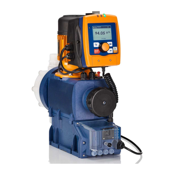
Operating instructions
Diaphragm Motor-driven Metering Pump
Sigma/ 2 Control type S2Cb
EN
Please carefully read these operating instructions before use. · Do not discard.
The operator shall be liable for any damage caused by installation or operating errors.
The latest version of the operating instructions are available on our homepage.
Part no. 985454
Original Operating Instructions (2006/42/EC)
BA SI 073 03/17 EN
Advertisement
Table of Contents

Related Manuals for ProMinent Sigma/ 2 Control S2Cb


Summary of Contents for ProMinent Sigma/ 2 Control S2Cb
-
Page 1: Operating Instructions
Operating instructions Diaphragm Motor-driven Metering Pump Sigma/ 2 Control type S2Cb Please carefully read these operating instructions before use. · Do not discard. The operator shall be liable for any damage caused by installation or operating errors. The latest version of the operating instructions are available on our homepage. Part no. - Page 2 Supplemental directives Supplementary information Read the following supplementary information in its entirety! Should you already know this information, you will benefit more from referring to the operating instructions. The following are highlighted separately in the document: Enumerated lists Fig. 1: Please read! Handling instructions ð...
-
Page 3: Table Of Contents
Table of contents Table of contents Identity Code................... 5 Safety Chapter................. 8 Storage, Transport and Unpacking..........12 Overview of equipment and control elements....... 13 4.1 Key functions................. 15 4.2 LCD screen identifiers............15 Functional Description..............18 5.1 Pump..................18 5.2 Liquid end................19 5.3 Bleed valve and integrated relief valve ........ - Page 4 Table of contents 8.7.3 HMI logout................60 8.7.4 Security (SECURITY menu)..........61 8.8 Information about the pump (INFORMATION menu).... 62 8.9 Set language (LANGUAGE menu)........62 Start Up..................64 Operation..................67 10.1 Manual................67 10.2 Remote operation..............69 Maintenance.................. 70 Carrying out repairs...............
-
Page 5: Identity Code
Identity Code Identity Code S2Cb Sigma 2, Control Type, Version b Product range S2Cb Power end type Main power end, diaphragm Type Capacity _ _ _ _ _ Performance data at maximum back pressure and type: refer to nameplate on the pump housing Dosing head material PVDF... - Page 6 Identity Code S2Cb Sigma 2, Control Type, Version b With ProMinent ® logo Without ProMinent ® logo Physiological safety with FDA No. 21 CFR §177.1550 regard to wetted materials (PTFE) FDA No. 21 CFR §177.2510 (PVDF) Electric power supply 1 ph, 100-230 V ± 10%, 50/60 Hz...
- Page 7 Identity Code S2Cb Sigma 2, Control Type, Version b Dosing monitor, dynamic, with access control Language German English Spanish French FPM = fluorine rubber ** Pump without HMI control unit...
-
Page 8: Safety Chapter
EHEDG (www.ededg.org). Observe the general limitations with regard to viscosity limits, chem‐ ical resistance and density - see also the ProMinent Resistance List (in the Product Catalogue or at www.prominent.com)! All other uses or modifications are prohibited. - Page 9 Service Customer Service department refers to service technicians, who have received proven training and have been authorised by ProMinent or Pro‐ Maqua to work on the system.
- Page 10 Safety Chapter Safety information WARNING! Warning of hazardous feed chemical Should a dangerous feed chemical be used: it may escape from the hydraulic components when working on the pump, material failure or incorrect handling of the pump. – Take appropriate protective measures before working on the pump (e.g.
- Page 11 The use of untested third party parts can result in per‐ sonnel injuries and material damage. – Only fit parts to metering pumps, which have been tested and recommended by ProMinent. CAUTION! Danger from incorrectly operated or inadequately main‐ tained pumps Danger can arise from a poorly accessible pump due to incorrect operation and poor maintenance.
-
Page 12: Storage, Transport And Unpacking
The "Decontamination Declaration Form" can be found at www.prominent.com. WARNING! Slings can tear ProMinent only supplies “non-reusable slings” in accord‐ ance with DIN EN 60005. They can tear with repeated use. – Destroy and remove the slings as soon as the pump has been lifted into its final position. -
Page 13: Overview Of Equipment And Control Elements
Overview of equipment and control elements Overview of equipment and control elements Overview of Equipment P_SI_0125_SW Fig. 2: Overview of equipment S2Cb HMI control unit Frequency converter Drive unit Stroke length adjustment wheel Drive motor Liquid end Diaphragm rupture sensor Control elements P_SI_0088_SW Fig. - Page 14 Overview of equipment and control elements P_SI_0105_SW Fig. 4: HMI control elements LCD screen Fault indicator (red) Warning indicator (yellow) Operating indicator (green) [i] key / Cursor to right [ESC] key [START/STOP] key [DOWN] key [P / OK] key [UP] key P_SI_0106_SW_2 Fig.
-
Page 15: Key Functions
Overview of equipment and control elements 4.1 Key functions Application In continuous displays (operation) In adjustment mode (set up) [STOP/START] Pressed briefly Stop pump, Stop pump, start pump start pump [P / OK] „Batch“ oper‐ Pressed briefly Start batch (only in Confirm entry - jump to next menu ating mode), option or to continuous display... - Page 16 Overview of equipment and control elements 1 2 3 4 B0413 Operating main display Source indicator for stop Auxiliary operation / Diaphragm break sensor deactivated Module option Mode Main display Secondary display Display type (number of pages) Other identifiers, error source indicator 10 Continuous display identifier ("...
- Page 17 Overview of equipment and control elements Field no. Icon Name Meaning MANUAL „Manual“ „Manual“ operating mode „Contact“ „Contact“ operating mode CONTACT „Batch“ „Batch“ operating mode BATCH „Analog“ „Analog“ operating mode ANALOG Error A fault exists. Stroke length adjust‐ Deviation in the stroke length from the value set at the ment time of the last locking of the setting menu.
-
Page 18: Functional Description
Functional Description Functional Description 5.1 Pump The metering pump is an oscillating diaphragm pump, the stroke length of which can be adjusted. An electric motor drives the pump. The slide rod transmits the stoke motion to the diaphragms. Illustration of the stroke movement The stroke movement of the displacement body is continuously measured and regulated so that the stroke is executed according to a previously set „Metering“... -
Page 19: Liquid End
Functional Description With a suction optimised dosing profile, the suction stroke is elongated as much as possible, which makes possible a precise and problem-free dosing of viscous and gaseous media. Select this setting to minimise the NPSH value as well. P_SI_0104_SW 5.2 Liquid end The diaphragm (2) hermetically shuts off the pump volume of the dosing... -
Page 20: Multi-Layer Safety Diaphragm
Functional Description The integral relief valve can only protect the motor and the gear, and then only against impermissible positive pressure that is caused by the metering pump itself. It cannot protect the system against positive pres‐ sure. The integral relief valve works as a bleed valve as soon as the rotary dial (3) is turned to "open": The valve opens and the liquid end can be bled. -
Page 21: Functions
„BUS“ operating mode (Identity code, control variant: CANopen or PRO‐ FIBUS DP interface). This operating mode provides the option of control‐ ® ling the pump via BUS (see “Supplementary instructions for ProMinent delta and Sigma with PROFIBUS ® ". 5.6 Functions... -
Page 22: Options
Functional Description "Level switch" function: Information about the liquid/powder level in the chemical feed container is reported to the pump control. To do so, a two- stage level switch must be fitted; it is connected to the "Level switch" ter‐ minal. -
Page 23: Lcd Screen
Functional Description 5.9 LCD screen If a fault occurs, the identifier „Error“ appears and an additional error mes‐ sage. 5.10 LED Displays CANopen status display (green): The CANopen status indicator shows the status of the CANopen bus. Colour Flash code Cause Conse‐... -
Page 24: Assembly
Assembly Assembly Refer to the correct dimensional drawings on our web‐ site www.prominent.com for assistance. Compare the dimensions on the dimension sheet with those of the pump. Base WARNING! Danger of electric shock If water or other electrically conducting liquids penetrate into the drive housing, in any other manner than via the pump's suction connection, an electric shock may occur. - Page 25 Assembly If the HMI is mounted remotely from the pump: a clearly marked Stop mechanism must be installed in the direct vicinity of the pump for emer‐ gencies! Discharge valve Dosing head Suction valve Ensure there is sufficient free space (f) around the dosing head as well as the suction and discharge valve so that maintenance and repair work can be carried out on these components.
-
Page 26: Installation
Installation Installation CAUTION! Danger of injury to personnel and material damage The disregard of technical data during installation may lead to personal injuries or damage to property. – Observe the technical data- refer to chapter "Tech‐ nical Data" and, where applicable, the operating instructions of the accessories. - Page 27 P_SI_0021 grooved pump valves and the grooved inserts from Ä Further information on page 26 . Fig. 14: Moulded composite seals with ProMinent - see corrugated insert – In the event that an unflared insert is used (e.g. third party part), an elastomer flat seal must be used -...
- Page 28 Installation Precise metering is only possible when the back – pressure is maintained above 1 bar at all times. If metering at atmospheric pressure, a back pres‐ – sure valve should be used to create a back pressure of approx. 1.5 bar. P_SI_0022 CAUTION! Fig.
- Page 29 Installation CAUTION! Danger due to incorrect use of the integral relief valve The integral relief valve can only protect the motor and the gear, and then only against impermissible positive pressure that is caused by the metering pump itself. It cannot protect the system against positive pressure.
-
Page 30: Basic Installation Notes
Installation When operating the integral relief valve close to the opening pressure, a minimal overflow into the overflow line can occur. Diaphragm rupture sensor CAUTION! Danger resulting from unnoticed diaphragm rupture If the pump has been ordered with an electric diaphragm rupture sensor, it still has to be installed. -
Page 31: Installation, Electrical
– If the housing of the motor or electrical ancillaries has been damaged, you must disconnect it from the mains immediately. Only return the pump to service after an authorised repair. CAUTION! Use ProMinent cables to avoid unnecessary problems. -
Page 32: Control Connectors
Installation What requires electrical installation? What requires electrical installation? Level switch Diaphragm rupture sensor, electrical (option) Metering monitoring (option) Relay (option) External control mA Output (Optional) Bus connector (optional) Timer (option) Pump, power supply 7.2.1 Control connectors CAUTION! Incoming signals can remain without effect If the universal control wire, the external/pacing cable or the level monitoring cable is shortened below 1.20 m, the pump does not detect that it is connected. - Page 33 Installation 7.2.1.1 Relay 7.2.1.1.1 Fault indicating relay 230 V If another switching function is required, the pump can be reprogrammed „Relay“ menu. in the The relay can be retrofitted and operates once it is plugged into the relay board. P_SI_0111_SW Fig.
- Page 34 Installation Data Value Unit Maximum voltage 24 VDC Closing duration 100 ms Fault indicating and pacing relay option Pin assignment To pin VDE cable Contact Relay yellow NC (normally closed) or Fault indi‐ cating relay P_SI_0044 NO (normally open) Fig. 23: Cable assignment green C (common) Fault indi‐...
- Page 35 Installation Current output and fault indicating / pacing relay (24 V) To pin VDE cable Contact Relay yellow "+" Current output green "-" Current output P_SI_0044 white NC (normally closed) or Fault indi‐ Fig. 25: Cable assignment cating / NO (normally open) pacing relay brown C (common)
- Page 36 2 white / Contact External activation 4 brown / GND Pulse frequency, e.g. contact water meter, PLC etc. Function "External Contact" (ProMinent universal control wire) 3 blue / Analog 5-core 2 white / Contact External 1 brown / Pause activation...
- Page 37 Installation Technical data "external control" Semi-conductor switch elements with a residual voltage of -0.7 V (e.g. transistors in open-collector circuits) or contacts (relays) can be used as input switch elements. P_BE_0014_SW Pin 1 = Pause input (activating func‐ Voltage with open contacts: approx.
- Page 38 Installation Block diagram Sigma Control Inputs Outputs Pump, inside Empty signal 3 brown / Pause Level Warning 2 blue / Alarm sensor 1 black / GND VDE cable: 2 green / NC (fault alert) 1 brown / 5 V Fault indicating 1 white / NO Stroke 2 white / Cod.
-
Page 39: Hmi Operating Unit
2 white / Contact External activation 4 brown / GND Pulse frequency, e.g. contact water meter, PLC etc. Function "External Contact" (ProMinent universal control wire) 3 blue / Analog 5-core 2 white / Contact External 1 brown / Pause activation... -
Page 40: Pump, Power Supply
Installation If the pump is operated without the HMI, the supplied sealing cap must be plugged into the CAN port above the LEDs of the pump base. CAUTION! Risk of short circuit If liquid penetrates into the CAN port, a short circuit may occur in the pump. -
Page 41: Other Units
Installation CAUTION! Pump can be damaged The pump can only be stopped when running via an: – External cable [Stop] key. – Use a relay or a contactor if the pump has to be defini‐ tively actuated via the mains cable. However, take into account the pump’s starting current. -
Page 42: Setting
Setting Setting Please read the overviews in the appendix, "Control – elements and key functions" and "Operating/setting diagram" for supplementary information. If no key is pressed for a 1 minute duration, the – pump returns to a continuous display. 8.1 Basic Principles for Setting up the Control = Setting option = Adjustable Settings... -
Page 43: Changing To Set Up Mode
Setting The number of continuous displays depends on the iden‐ tity code, the selected operating mode and the con‐ nected additional devices, see overview "Continuous displays" in the appendix. A horizontal scroll bar shows the number of continuous displays and error messages and the position of the dis‐ played continuous display or error message. -
Page 44: Selecting The Operating Mode (Menu "Mode")
Setting Menu Mode Menu Settings Continuous Main menu Mode Settings display Service Information Language Menu Service Menu Information Menu Language 8.4 Selecting the operating mode (Menu "Mode") „Mode“ menu (depending on the identity code, some operating In the modes may not be present) the following operating modes can be selected: „Manual“... -
Page 45: Manual" Operating Mode Settings
Setting As to whether or not a further setting menu is available, depends on the selected operating mode and the connected devices or modules. Main menu Continuous Menu Menu Mode Set-up Set-up Set-up Mode** display Service Information Language Menu Timer* Timer* Menu Profibus*... -
Page 46: Contact" Operating Mode Settings
Setting Memory Main menu Settings Batch Mode Batch Memory Settings Auxiliary freq. Factor Service Calibrate Information Dosing Language Relay Factor Batch Memory Factor 0 0 0 0 5 Continuous display „Batch“ is one variant of the „Contact“ operating The operating mode mode - see the following chapter. - Page 47 Setting CAUTION! The pump maintains the stroke rate when changing over „Manual“ operating mode to „Contact“ operating from mode. The stroke rate can also be set in „Contact“ operating mode. It should normally be set to the maximum stroke rate. Memory Main menu Settings...
- Page 48 Setting Table of examples Factor Pulse (sequence) Number of strokes (sequence) Step-up* 100.00 100.00 1.50 1.50 (1 / 2) 1.25 1.25 (1 / 1 / 1 / 2) Step-down** 0.50 0.10 0.01 0.25 0.40 2.5 (3 / 2) (1 / 1) 0.75 1.33 (2 / 1 / 1) (1 / 1 / 1)
-
Page 49: Analog" Operating Mode Settings
Setting Non-processed pulses The device stores the number of pulses received, which could not yet be processed, in the stroke memory (if it was enabled). [STOP/START] is pressed or the "Pause" function is enabled, the When stroke memory is deleted. You can avoid this with the "Memory"... - Page 50 Setting Standard Main menu Settings Analog Mode Analog Standard 0..20mA Settings Auxiliary freq. Extended 4..20mA Service Calibrate Information Dosing Language Relay Continuous display „Extended“ - „Curve type“ processing types, you can freely pro‐ Extended Under gram the pump behaviour. There are 3 curve types: „linear“...
- Page 51 Setting I [mA] B0088 Fig. 28: Rate(frequency)-Current Diagram for Linear control Plot a diagram similar to the one above – with values for (I1, F1) and (I2, F2) – so that you can set the pump as desired! „Lower side band“ Using this type of processing, you can control a metering pump using the current signal as shown in the diagram below.
-
Page 52: Programmable Function Settings ("Settings" Menu )
Setting „Analog error“ you can activate error processing for Error processing Under menu option processing type „Curve“ . For current signals below 3.8 mA, an error mes‐ sage appears and the pump stops. Main menu Settings Analog Mode Analog Standard Settings Auxiliary freq. -
Page 53: Settings For The "Calibration" Function (Calibration Menu)
Setting 8.6.2 Settings for the “Calibration” function (CALIBRATION menu) Calibrate Main menu Settings Calibrate Mode Batch Calibr. running Settings Auxiliary freq. 32.90 mL 0107 Service Calibrate Information Dosing Start with OK Stop with OK Language Calibr. quant. 0 0 0 3. 0 8 L Continuous display The pump can also be operated in the calibrated state. -
Page 54: Settings For The "Metering" Function (Dosing Menu)
Setting „End“ and then press the key [P/OK] - the pump Select the option changes to a continuous display. ð The pump is calibrated. The corresponding continuous displays indicate the calibrated values. 8.6.3 Settings for the “Metering” function (DOSING menu) The "Dosing"... - Page 55 Setting „Metering è Pressure stage“ you can reduce the nominal pressure Pressure stage Under of the pump via the pressure stages – refer to the "Functional Description” chapter. Nominal pressures depending on the size of the liquid ends and the pressure stages Pressure stage / Size of liquid end 16050 *...
-
Page 56: Settings For The "Dosing Monitor" Function (Dosing Monitor Menu)
Setting 8.6.4 Settings for the “Dosing monitor” function (DOSING MONITOR menu) Dosing control Main menu Settings Mode Analog control Settings Auxiliary freq. Tolerance Service Calibrate at auxiliary Information Dosing monitor Signalization Language Relay Tolerance 0 0 1 0 at auxiliary Signalization Continuous display... -
Page 57: Settings For The "Relay" Function (Relay Menu)
Setting 8.6.5 Settings for the “Relay” function (RELAY menu) Main menu Settings Relay Mode Analog Relay1 Settings Auxiliary freq. relay2 Service Calibrate Information Dosing Language Relay Relay1 Relay type Warning Relay type Error Polarity Warn.+Error Warn+Err+Stop Stop Polarity Energizing (NO) Releasing (NC) Continuous display... -
Page 58: Settings For The "Analog Output" Function (Analog Output Menu)
Setting 8.6.6 Settings for the “Analog output” function (ANALOG OUTPUT menu) Analog output Range Main menu Settings 0..20mA Mode Analog Range Settings Auxiliary freq. 4..20mA Function Service Calibrate Information Dosing Language Analog output Function Strokes / min Capacity Capacity at 20mA Continuous display Using the "Analog output"... -
Page 59: Settings For The "Diaphragm Break" Function (Diaphragm Break Menu)
Setting - Output current in mA - Stroke rate in strokes/min - Current litre output „ Capacity at 20 mA“ - Maximum stroke rate in strokes/min The current output emits a current of 20 mA above the value set here for „Capacity at 20 mA“... -
Page 60: Clear Counters (Clear Counters Menu)
Setting 8.7.1 Clear counters (CLEAR COUNTERS menu) Clear counters Main menu Service Mode Clear counters Settings Display Stroke counter Service HMI logout Quantity counter Information Security Language Continuous display „CLEAR COUNTERS“ menu, you can either delete the stored total In the „Stroke counter“... -
Page 61: Security (Security Menu)
Setting To logout run through the menu above. Thereafter the HMI can be removed from the pump. Logging on takes place automatically whenever the HMI cable is con‐ nected to the CAN port. If the HMI must be formally logged into: Logging on via the menu occurs in exactly the same way as logging off. -
Page 62: Information About The Pump (Information Menu)
Setting If an Access protect is then set after 1 minute a padlock will appear instead of the " i " in the top left of the contin‐ uous display if in the meantime no key has been pressed. 8.7.4.2 Password In this menu enter the number you want to use as a password. - Page 63 Setting „LANGUAGE“ menu, you can select the desired operating lan‐ In the guage.
-
Page 64: Start Up
Start Up Start Up Safety information WARNING! Fire hazard with flammable media Only with flammable media: They can be ignited by oxygen. – The pump may not work if there is a mixture of feed chemical with oxygen in the liquid end. A specialist may need to take appropriate actions (using inert gas, ...). - Page 65 Start Up CAUTION! Possible environmental and material damage In event the red gear bleeding plug is sealed, during operation it prevents any pressure compensation between the drive housing and the surroundings. This ensure that oil can be pushed from the drive housing. –...
- Page 66 Start Up When operating the integral relief valve close to the opening pressure, a minimal overflow into the overflow line can occur. Adjusting the stroke length Only adjust the stroke length when the pump is running. This is easier and also better for the pump. P_SI_0095_SW Fig.
-
Page 67: Operation
Operation Operation WARNING! Fire hazard with flammable media Only with flammable media: They can be ignited by oxygen. – The pump may not work if there is a mixture of feed chemical with oxygen in the liquid end. A specialist may need to take appropriate actions (using inert gas, ...). - Page 68 Operation The following operating options are available via the keys - see the next figure: [STOP/START] key. Stop/start pump Stop the pump: Press the [STOP/START] key again. Start the pump: press the Starting a batch „Batch“ operating mode: briefly press key [P/OK] . [P/OK] key pressed for 2 s, the pump Changing to set up mode In continuous display if you keep the...
-
Page 69: Remote Operation
Operation „Batch“ mode: The batch variable is the metering volume, which is Batch size Only in metered at an external pulse or pressing of key [P/OK] . [arrow keys] is not precise enough, use the stroke If adjustment using the adjustment dial for fine adjustment. -
Page 70: Maintenance
Maintenance Maintenance Safety information WARNING! Fire hazard with flammable media Only with flammable media: They can be ignited by oxygen. – The pump may not work if there is a mixture of feed chemical with oxygen in the liquid end. A specialist may need to take appropriate actions (using inert gas, ...). - Page 71 Use only original spare parts. – Use the correct spare parts kits. If in doubt, refer to – the exploded views and ordering information on our website www.prominent.com. Standard liquid ends: Interval Maintenance work Personnel After approx. 5,000 oper‐...
- Page 72 Maintenance Changing gear oil Draining gear oil P_SI_0143_SW Fig. 32 Remove the vent screw (1). Place an oil trough under the oil drainage plug (2). Unscrew the oil drainage plug (2) from the power end housing. Allow the gear oil to run out of the power end. Screw in the oil drainage plug (2) with a new seal.
-
Page 73: Carrying Out Repairs
Only use new components that are especially adapted to fit your valve (both in terms of shape and chemical resistance). Use the correct spare parts kits. If in doubt, refer to – the exploded views and ordering information on our website www.prominent.com. - Page 74 Carrying out repairs Only with the "Physiologically safe" design: WARNING! Product can be dangerously contaminated Only use the spare parts from the "Physiologically safe" spare parts kits. Personnel: Technical personnel Repairing ball valves CAUTION! Warning of personal injury and material damage Feed chemical may escape from the liquid end, for example, if ball valves not repaired correctly.
-
Page 75: Replacing The Diaphragm
– Use only original spare parts. Use the correct spare parts kits. If in doubt, refer to – the exploded views and ordering information on our website www.prominent.com. Personnel: Technical personnel Requirements: If necessary take protective measures. Adhere to the material safety data sheet for the feed chemical. - Page 76 Should this not work, remove dirt or swarf out of the thread and screw the diaphragm correctly onto the drive axle this time. ð If this is still unsuccessful, contact ProMinent-ProMaqua cus‐ tomer service. Place the dosing head with the screws onto the diaphragm - the suction connector should be pointing downwards in the pump's fit‐...
- Page 77 Carrying out repairs Check whether it can move freely in the hole. Refit the clean diaphragm rupture sensor with the clean piston. Test the diaphragm rupture sensor. Optical diaphragm rupture sensor Unscrew the transparent cover from the diaphragm rupture sensor. Press the red cylinder into the diaphragm rupture sensor until it engages.
- Page 78 Carrying out repairs P_SI_0038 Fig. 36: Cross-section through the liquid end Suction valve Diaphragm Discharge valve Dosing head Backplate 13 Safety diaphragm...
-
Page 79: Troubleshooting
Troubleshooting Troubleshooting Safety information WARNING! Fire hazard with flammable media Only with flammable media: They can be ignited by oxygen. – The pump may not work if there is a mixture of feed chemical with oxygen in the liquid end. A specialist may need to take appropriate actions (using inert gas, ...). -
Page 80: Fault Messages
Troubleshooting Fault description Cause Remedy Personnel Serious crystalline deposits Dismantle the valves and clean them - refer Technical on the ball seat due to the to the "Overhaul" chapter. personnel valves drying out. Fluid is escaping from the The screws in the dosing Tighten the screws in the dosing head in a backplate. -
Page 81: Warning Messages
Troubleshooting Fault description Cause Remedy Personnel The symbol "Stroke length adjustment" The stroke adjustment dial Turn the stroke adjustment Technical STRKappears flashing on the LCD was rotated by more than dial back or enter the pass‐ personnel „Stroke 10% while the menu was word. -
Page 82: All Other Faults
„CANopen pump“ W8-3. pump. 13.4 All Other Faults Please contact the responsible ProMinent branch or agency, see www.prominent.com - "Contact" - "Your contact worldwide" or as the case may be, the published by details of these operating instructions. -
Page 83: Decommissioning
Decommissioning Decommissioning Decommissioning WARNING! Fire hazard with flammable media Only with flammable media: They can be ignited by oxygen. – The pump may not work if there is a mixture of feed chemical with oxygen in the liquid end. A specialist may need to take appropriate actions (using inert gas, ...). - Page 84 Decommissioning CAUTION! Warning of feed chemical spraying around Feed chemical can spray out of the hydraulic compo‐ nents if they are manipulated or opened due to pressure in the liquid end and adjacent parts of the system. – Disconnect the pump from the mains power supply and ensure that it cannot be switched on again by unauthorised persons.
- Page 85 Decommissioning CAUTION! Environmental hazard due to gear oil The pump contains gear oil, which can cause damage to the environment. – Drain the gear oil from the pump. – Note the local guidelines currently applicable in your country!
-
Page 86: Technical Data
Technical data Technical data 15.1 Performance data S2Cb Type Minimum pump capacity at maximum Max‐ Suction Permis‐ Connector back pressure imum lift sible pri‐ size stroke ming pres‐ rate sure, suction side Strokes/ ml/stroke m WS R"-DN 16050 PVT 11.4 1"... -
Page 87: Viscosity
Technical data 15.2 Viscosity The liquid ends are suitable for the following viscosity ranges: Version Stroke rate, max. Viscosity Strokes/min mPas Standard 0 ... 200 With valve springs 200 ... 500 With valve springs and 500 ... 1000* suction-side feed * Only when the installation is correctly adjusted 15.3 Shipping weight... -
Page 88: Media Temperatures
Technical data 15.5.2 Media temperatures PVT liquid end Data Value Unit Max. temperature long-term at max. oper‐ 65 °C ating pressure Max. temperature for 15 min at max. 2 bar 100 °C Minimum temperature -10 °C SST liquid end Data Value Unit Max. -
Page 89: Electrical Connection
Value Order No. Fuse, internal 6.3 AT - (1.5 kA) 732379 Only use the original fuses from ProMinent! It is not suffi‐ cient to use a fuse with the above fuse rating. 15.8 Diaphragm rupture sensor Contact (standard) Contact loading, max. -
Page 90: Relay
Technical data For safety reasons we recommend connecting to a – protective low voltage, e.g. in accordance with EN 60335-1 (SELV ). The cable can be poled as required. – Namur sensor (Specified for EX zones) 5–25 V DC, in accordance with Namur or DIN 19234, potential-free design. -
Page 91: Design Documents
Design Documents Design Documents Design documents, such as dimensional drawings, ordering data (exploded drawings), performance dia‐ grams ... are available in the relevant online version of these operating instructions on our website. When searching on the website, please use simply the 6-digit order number for these operating instructions - this can be found at the bottom left corner of the cover page. -
Page 92: Declaration Of Conformity For Machinery
Appendix I, No. 1.5.1 of the Machinery Directive EMC Directive (2014/30/EU) Harmonised standards applied, in EN ISO 12100 particular: EN 809:1998 - A1:2009 + AC:2010 EN 61010-1:2010 EN 61000-6-2:2005 + AC:2005 EN 61000-6-4:2007 + AC:2011 Date: 20/04/2016 View the EC Declaration of Conformity at www.prominent.com. -
Page 93: Operating / Adjustment Overview
Operating / adjustment overview Operating / adjustment overview Continuous display Stop/start pump Change directly changeable variables Priming Start batch (only in "Batch" mode) Acknowledge errors Check adjustable values "Lock menu" "Lock all" Main menu Menu Menu Mode Settings Settings Settings Mode** Mode** Service... -
Page 94: Continuous Displays
Continuous displays Continuous displays... - Page 95 Continuous displays...
-
Page 96: Index
Index Index Diaphragm ....... 19 1, 2, 3 ... Diaphragm rupture ......59 "External control"... - Page 97 Index HMI logout ....... 60 Operation ....... 67 HMI operating unit .
- Page 98 Index Software versions ......62 Sound pressure level ..... 11, 90 Standard .
- Page 100 ProMinent GmbH Im Schuhmachergewann 5-11 69123 Heidelberg, Germany Germany Telephone: +49 6221 842-0 Fax: +49 6221 842-419 Email: info@prominent.com Internet: www.prominent.com Heidelberg, 5, en_GB © 2012...
Need help?
Do you have a question about the Sigma/ 2 Control S2Cb and is the answer not in the manual?
Questions and answers