Table of Contents
Advertisement
Quick Links
Operating instructions
Piston Metering Pump
Sigma/ 2 Control type SCKa
P_SI_0136_SW
Please carefully read these operating instructions before use! · Do not discard!
The operator shall be liable for any damage caused by installation or operating errors!
Technical changes reserved.
Part no. 984860
Original operating instructions (2006/42/EC)
BA SI 060 11/13 EN
Advertisement
Table of Contents

Related Manuals for ProMinent SCKa Series


Summary of Contents for ProMinent SCKa Series
-
Page 1: Operating Instructions
Operating instructions Piston Metering Pump Sigma/ 2 Control type SCKa P_SI_0136_SW Please carefully read these operating instructions before use! · Do not discard! The operator shall be liable for any damage caused by installation or operating errors! Technical changes reserved. Part no. - Page 2 Supplemental instructions Supplementary information Read the following supplementary information in its entirety! Should you already know this information, you will benefit more from referring to the operating instructions. The following are highlighted separately in the document: Enumerated lists Fig. 1: Please read! Operating guidelines ð...
-
Page 3: Table Of Contents
Table of contents Table of contents Identity code..................5 Safety chapter................. 7 Storage, transport and unpacking..........11 Overview of equipment and control elements....... 12 Functional description..............13 5.1 Liquid End................13 5.2 Operating modes..............13 5.3 Functions................14 5.4 Options.................. 15 5.5 Function and fault indicator........... - Page 4 Table of contents Technical data................55 14.1 Performance data..............55 14.2 Shipping weight..............56 14.3 Viscosity................56 14.4 Wetted materials..............56 14.5 Ambient conditions.............. 56 14.5.1 Ambient temperatures............56 14.5.2 Media temperatures............56 14.5.3 Air humidity..............57 14.6 Relay................... 57 14.7 Gear oil................
-
Page 5: Identity Code
Piston (oxide ceramic) Dosing head design no valve springs with 2 valve springs, Hastelloy C; 0.1 bar Hydraulic connector Standard threaded connector (in line with technical data) Design With ProMinent ® logo (standard) Without ProMinent ® logo Electric power supply 1 ph, 100-230 V, ±... - Page 6 Identity code SCKa Sigma 2 control type Access code no access code with access code Dosing monitor Input with pulse evaluation Input with continuous evalua‐ tion Stroke length adjustment Manual...
-
Page 7: Safety Chapter
Observe the general restrictions with regard to viscosity limits, chem‐ ical resistance and density - see also ProMinent Resistance List (in the Product Catalogue or at www.prominent.com/en/downloads)! All other uses or modifications are prohibited. - Page 8 Service Customer Service department refers to service technicians, who have received proven training and have been authorised by ProMinent or Pro‐ Maqua to work on the system. Safety notes WARNING!
- Page 9 An unsuitable feed chemical can damage the parts of the pump that come into contact with the chemical. – Take into account the resistance of the wetted materials when selecting the feed chemical - see the ProMinent product catalogue or visit www.prominent.com/en/down‐ loads. CAUTION!
- Page 10 Safety chapter WARNING! An on/off switch may not be fitted on the pump, dependent on the identity code and installation. Isolating protective equipment All isolating protective equipment must be installed for operation: Drive front cover Motor fan cowling Terminal box cover, motor Hood In exactly the same way, plug all relays, modules and options into the hood - if available.
-
Page 11: Storage, Transport And Unpacking
The "Decontamination Declaration Form" can be found at www.prominent.com/en/downloads. WARNING! Slings can tear ProMinent only supplies non-reusable slings. These can tear with repeated use. – Only use the slings once. CAUTION! Danger of material damage... -
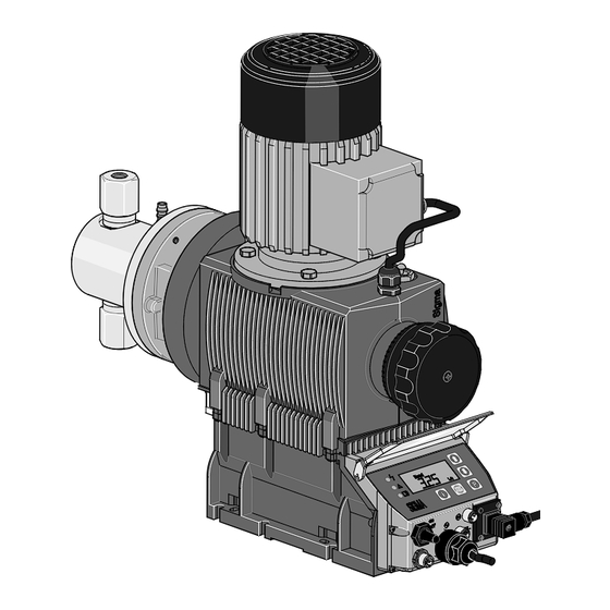
Page 12: Overview Of Equipment And Control Elements
Overview of equipment and control elements Overview of equipment and control elements P_SI_0139_SW Fig. 2: Overview of equipment and control elements SCKa Liquid end Drive motor Gear bleeding plug Drive unit Stroke length adjustment knob Control unit 75 % 50 % Fig. -
Page 13: Functional Description
Functional description Functional description The metering pump is an oscillating diaphragm pump, the stroke length of which can be adjusted. An electric motor drives the pump. 5.1 Liquid End The heart of the liquid end is a highly resistant piston (4) made from coated stainless steel. -
Page 14: Functions
‘BUS’ operating mode (Identity code, control variant: CANopen or PRO‐ FIBUS This operating mode provides the option of controlling the pump ® via a BUS (see “Supplementary instructions for ProMinent® gamma/ L and ProMinent Sigma versions with PROFIBUS ". ®... -
Page 15: Options
Functional description "Priming" function: Priming (short-term transport at maximum frequency) can be triggered by simultaneous pressing of the two arrow keys in the "Stroke rate" continuous display. 5.4 Options Relay option The pump has two connecting options (not with PROFIBUS or timer): ®... - Page 16 Functional description Comments: re 1 - "Priming" can take place in any mode of the pump (providing it is functioning). re 2 - "Fault", "Stop" and "Pause" stop everything apart from "Priming". re 3 - The stroke rate of "Auxiliary rate" always has priority over the stroke rate specified by an operating mode or priority 4.
-
Page 17: Assembly
Assembly Assembly Compare the dimensions on the dimension sheet and pump. Base WARNING! Danger of electric shock If water or other electrically conducting liquids penetrate into the drive housing, in any other manner than via the pump's suction connection, an electric shock may occur. –... - Page 18 Assembly Liquid end alignment Capacity too low The liquid end valves cannot close correctly if they are not upright. Ensure that the discharge valve is upright. – Fastening Capacity too low Vibrations can disrupt the liquid end valves. Secure the metering pump so that no vibrations can –...
-
Page 19: Installation
Installation Installation CAUTION! Danger of injury to personnel and material damage The disregard of technical data during installation may lead to personal injuries or damage to property. – Observe the technical data- refer to chapter "Technical Data" and, where applicable, the operating instructions of the accessories. - Page 20 Installation CAUTION! Warning against the discharge line bursting With a closed discharge line (e.g. due to a clogged discharge line or by closing a valve), the pressure that the metering pump generates can reach several times the permissible pressure of the system or the metering pump. This could lead to lines bursting, resulting in dangerous consequences with aggressive or toxic feed chemicals.
- Page 21 Installation Standard installation P_MAZ_0001_SW Fig. 9: Standard installation Main line Storage tank Symbols for the components Symbol Explanation Symbol Explanation Injection valve Multifunctional valve Manometer Relief valve (alterna‐ Metering pump tively a multifunction valve can be used) Level switch Foot valve with filter meshes Route the leakage liquid drainage line CAUTION!
-
Page 22: Installation, Electrical
Installation 7.2 Installation, electrical General safety notes WARNING! Danger of electric shock Unprofessional installation may lead to electric shocks. – Cable end sleeves must be crimped onto all cut-to- length cable conductors. – Only technically trained personnel are authorised to undertake the electrical installation of the device. - Page 23 Installation Relay technical data The contacts are potential-free. As a NC fault indicating relay the relay closes immediately after the power is switched on and opens in the event of a fault. As a N/O fault indicating relay, the relay closes in the event of a fault. Use suitable interference suppression (e.g.
- Page 24 Installation Data Value Unit Maximum voltage 24 VDC Maximum current 100 mA Closing duration 100 ms Service life * Play 50 x 10 (10 V, 10 mA) * at rated load Behaviour: - see identity code The contacts are potential-free. Fault indicating and pacing relay option Pin assignment To pin...
-
Page 25: Pump, Power Supply
Installation Fig. 13: Cable conductor assignments To pin VDE cable Contact CSA cable white NO (normally open) white green NC (normally closed) brown C (common) black Fault indicating and pacing relay option Pin assignment To pin VDE cable Contact Relay yellow NO (normally open) Fault indi‐... -
Page 26: Set Up
Set up Set up For supplementary information see "Control elements and key functions" in the chapter "Overview of equipment and control elements" and "Operating/setting overview" in the appendix. The pump control returns to the continuous display, as soon as no key has been pressed for one minute. 8.1 Basic principles of pump adjustment Installation option flashes... -
Page 27: Checking Adjustable Values
Set up Changing adjustable values [UP] or [DOWN] . Press the arrow keys ð The flashing digit or number counts up or down. Confirming adjustable values Under "change individual digits": confirm each digit by pressing the [P] key. ð Upon confirming the last individual digit, the display simultane‐ ously changes to the next menu option or into a continuous dis‐... -
Page 28: Selecting The Operating Mode (Mode Menu)
Set up To match the pump to your process requirements, you must observe the following procedure: ‘MODE’ menu select the operating mode. In the If necessary make the settings for this operating mode in the ‘SET’ menu. MODE MODE menu CODE CODE menu... -
Page 29: Operating Mode Settings (Set Menu)
Set up Analog - ANALOG Manual - MANUAL Analog Manual CONTACT Batch CONTACT - CONTACT Batch - BATCH Continuous display B0085 Fig. 18 8.5 Operating mode settings (SET menu) First in the ‘MODE’ menu select the operating mode! Exceptions: Timer and PROFIBUS ®... - Page 30 Set up Continuous display B0086 Fig. 19 You can select three types of current signal processing: ‘0 - 20 mA’ : – At 0 mA the pump is stationary. – At 20 mA the pump works at the maximum stroke rate. –...
- Page 31 Set up I [mA] B0088 Fig. 21 F1 Stroke rate at which the pump should operate with current I1 F2 Stroke rate at which the pump should operate with current I2 Plot a diagram similar to the one above - with values for (I1, F1) and (I2, F2) –...
-
Page 32: Contact" Operating Mode Settings (Cntct Menu)
Set up ‘ER’ (Error) you can activate error processing for the Error processing Under menu option ‘Curve’ processing type. For current signals below 3.8 mA, an error mes‐ sage appears and the pump stops. 8.5.3 "Contact" operating mode settings (CNTCT menu) Alongside those described in more detail in the chapter "Programmable ‘CNTCT’... - Page 33 Set up Example Example table Factor Pulse Number of (sequence) strokes (sequence) Step-up 99.99 99.99 1.50 1.50 (1 / 2) 1.25 1.25 (1 / 1 / 1 / Reduction 0.50 0.10 0.01 0.25 0.40 2.5 (3 / 2) (1 / 1) 0.75 1.33 (2 / 1 / 1) (1 / 1 / 1)
-
Page 34: Batch" Operating Mode Settings (Batch Menu)
Set up ‘Mem’ "Memory" function extension You can also activate the "Memory" function extension (identifier appears on the LCD screen; ‘Mem’ = memory). When "Memory" is acti‐ vated, the pump software adds up the remaining strokes , which could not be processed, up to the maximum capacity of the stroke memory of 65,535 strokes. -
Page 35: Calibrate" Function Settings (Calib Menu)
Set up 8.6.1 “Calibrate” function settings (CALIB menu) Continuous display B0093 Fig. 26 The pump can also be operated in the calibrated state. In this case, the corresponding continuous displays then indicate the metering volume or the capacity directly. The calibration is maintained when the stroke length is altered by up to ±10 scale divisions (for a set stroke length of 40 % this corresponds to a range from 30 % ... -
Page 36: Auxiliary Frequency" Function Settings (Aux Menu)
Set up ‘UNIT’ select the units ( ‘L’ or ‘gal’ ) using the Under menu option arrow keys and press the [P] key. ð The pump is calibrated. Consequence: The corresponding continuous displays indicate the calibrated values. Total number of strokes and total litres are set to "0" by calibrate. The pump is in the STOP state. -
Page 37: Deleting The Total Number Of Strokes Or Total Litres (Clear Window)
Set up In the first menu option, you can set either CODE 1 or CODE 2 (both use the same number). ‘CODE 1’ , to block adjustment mode (① in "Operating / adjust‐ Select ment overview" in the appendix). In the next menu option, enter the number you want to use as the code. -
Page 38: Operation
Operation Operation This chapter describes all the operating options available to you if the pump control is showing a continuous display - then the display does not [P] key. contain the symbol for the For supplementary information, please read the over‐ –... - Page 39 Operation [i] key toggles the continuous display output to the Checking adjustable values Each press of the screen to another continuous display. The number of continuous displays depends on the identity code, the selected operating mode and the con‐ nected additional devices. Change directly changeable variables To change a value, see below, directly in the corresponding continuous [arrow keys] until the [Set] identifier appears.
-
Page 40: Remote Operation
There is an option to control the pump remotely via a signal cable, PRO‐ FIBUS ® or CAN bus - see chapter "Settings - selecting the operating mode (MODE menu)" and chapter "Operation", in the "Supplementary instruc‐ tions for ProMinent gamma/ L and ProMinent Sigma versions with PRO‐ ® ® FIBUS ®... -
Page 41: Maintenance
Maintenance Maintenance Safety notes WARNING! It is mandatory that you read the safety information and specifications in the "Storage, Transport and Unpacking" chapter prior to shipping the pump. WARNING! Warning of dangerous or unknown feed chemical Should a dangerous or unknown feed chemical be used: It may escape from the hydraulic components when working on the pump. - Page 42 Maintenance Keep a spare parts kit in stock ready for maintenance work. Order numbers are given in the appendix. (7 Nm) (7.5 Nm) P_SI_0148_SW Fig. 31: Liquid end tightening torques Dosing head screws Turret flange screws Interval Maintenance work Quarterly* Check the starting torque torques for the dosing head flange screws (1) (7 Nm) and the turret flange screws (2) (7.5 Nm).
- Page 43 Maintenance Changing the gear oil WARNING! Risk of burns due to hot gear oil The gear oil may become very hot when the pump is heavily loaded – When draining oil, avoid contact with the oil running out. Gear oil Gear oil Supplied quantity Part no.
-
Page 44: Repairs
Repairs Repairs Safety notes WARNING! It is mandatory that you read the safety information and specifications in the "Storage, Transport and Unpacking" chapter prior to shipping the pump. CAUTION! Warning of feed chemical spraying around Feed chemical can spray out of the hydraulic components if they are manipulated or opened due to pressure in the liquid end and adjacent parts of the system. -
Page 45: Cleaning Double Ball Valves
Repairs 11.1 Cleaning double ball valves Cleaning a discharge valve Taking the discharge valve apart Unscrew the discharge valve from the dosing head and rinse out. Dismantle the discharge valve. Rinse and clean all parts. Replace the worn parts and seals. Assembling the discharge valve When assembling, take note of the orientation of the valve seats (3). -
Page 46: Changing The Piston
Repairs 11.2 Changing the piston WARNING! Observe the safety notes at the beginning of the chapter. Removing the liquid end Flush the suction line, discharge lines and liquid end (activate flushing equipment or immerse suction lance in a suitable medium and pump for a while (consider the effect of the medium on your system first!)) or proceed, as described below. - Page 47 Repairs P_SI_0145_SW Fig. 34: Cross-section through the liquid end Dosing head Piston Dosing head flange Flushing collar Guide ring Washer 16 Spring 20 V-sleeve packing 21 O-ring 23 FOI ring 24 Guide band 25 Dosing head flange screws 26 Liquid end retaining screws 27 Guide ring screws 31 Tube nozzles for leakage/flushing connector Repairing the liquid end...
- Page 48 Repairs Push the spring (16) and the washer (6) into the dosing head. CAUTION! The piston may be damaged – Do not damage the sealing lips of the V-sleeve packing (20). Push the V-sleeve packing (20) into the dosing head. The thicker ring comes last! Align the V-type rings with the open side towards the dosing head, as for the FOI ring (23), see Fig.
- Page 49 Repairs Attach the upper protective cover to the turret. If fitted: Connect the flushing tubes to the hose nozzles.
-
Page 50: Troubleshooting
Troubleshooting Troubleshooting Safety notes WARNING! Warning of dangerous or unknown feed chemical Should a dangerous or unknown feed chemical be used: It may escape from the hydraulic components when working on the pump. – Take appropriate protective measures before working on the pump (e.g. -
Page 51: Faults With Error Message
(max. 40 °C). Allow the motor to cool. [P] key (reset function). Press the Other motor faults. Contact ProMinent [P] key (reset function). Press the The red LED indicator illuminates, on the dis‐ The temperature inside the Ensure lower outside tempera‐... -
Page 52: Warning Alerts
Reset the stroke length or ‘Calib’ flashes. and the identifier more than ±10 scale divisions from the value at the recalibrate the pump at the time of the calibration. desired stroke length. 12.3 All Other Faults Please contact the responsible ProMinent branch or representative. -
Page 53: Decommissioning
Decommissioning Decommissioning Decommissioning WARNING! Danger of an electric shock When working on the motor or electrical auxiliary equipment, there is a danger of an electric shock. – Before working on the motor, take note of the safety instructions in its operating instructions! –... - Page 54 Decommissioning CAUTION! Danger of damage to the device The device can be damaged by incorrect and improper storage or transportation. – Take into account the information in the "Storage, Trans‐ port and Unpacking" chapter if the system is decommis‐ sioned for a temporary period. (Temporary) decommissioning Personnel: Technical personnel...
-
Page 55: Technical Data
Technical data Technical data Only for "M - modified" design: WARNING! Risk of personal injuries Please observe the ”Supplement for modified version“ at the end of the chapter! It replaces and supplements the technical data! 14.1 Performance data SCKa Type Minimum pump capacity at maximum back pres‐... -
Page 56: Shipping Weight
200 ... 500 mPas with appropriately laid 500 ... 1000 mPas out installation with appropriately laid > 1000 mPas out installation and advice from ProMinent 14.4 Wetted materials Liquid end Suction/pressure Seals / ball seat Balls Ball seat... -
Page 57: Air Humidity
Technical data 14.5.3 Air humidity Air humidity Data Value Unit Maximum air humidity *: 92 % rel. humidity * non-condensing 14.6 Relay The electrical data for the relay are contained in the chapter "Installation, electrical". 14.7 Gear oil Manufac‐ Name Viscosity Part no. -
Page 58: Diagrams For Adjusting The Capacity
Diagrams for adjusting the capacity Diagrams for adjusting the capacity SCKa SCKa C [l/h] C [l/h] 05016 01264 10011 02541 14006 02534 10006 04522 23004 04022 07012 32002 S [%] S [%] C [l/h] C [l/h] 05016 01264 10011 02541 14006 02534 10006... -
Page 59: Dimensional Drawings
Dimensional drawings Dimensional drawings Dimensional drawing Sigma SCKa 36.5 P_SI_0139_SW Fig. 37: Dimensional drawing Sigma SCKa - dimensions in mm Type Liquid end 32002, 23004, 10006 FK 08 Rp 1/4 (DN8) 14006, 10011, 05016 FK 12.5 Rp 1/4 (DN8) 07012, 04522, 02534 FK 25 Rp 1/4 (DN8) 04022, 02541, 01264... -
Page 60: Exploded Drawing Sigma Piston Metering Pump
Exploded drawing Sigma piston metering pump Exploded drawing Sigma piston metering pump Liquid end P_SI_0137_SW Fig. 38: * The items listed are included in the spare parts kit. -
Page 61: Sigma/ 2 Piston Ordering Information
Sigma/ 2 piston ordering information Sigma/ 2 piston ordering information Spare parts kits normally include the wearing parts of a liquid end. Other locations where ordering information can be found: Exploded drawings, ProMinent product catalogue, ® www.prominent.com/en/downloads. Spare parts kits SST (liquid ends) -
Page 62: Ec Declaration Of Conformity For Machinery
In accordance with DIRECTIVE 2006/42/EC OF THE EUROPEAN PAR‐ LIAMENT AND OF THE COUNCIL, Appendix I, BASIC HEALTH AND SAFETY REQUIREMENTS, section 1.7.4.2. C. ProMinent Dosiertechnik GmbH Im Schuhmachergewann 5 - 11 D - 69123 Heidelberg, hereby declares that the product specified in the following, complies with... -
Page 63: Operating / Adjustment Overview
Operating / adjustment overview Operating / adjustment overview Continuous display Stop/start pump = Lock (CODE 1) Change directly changeable variables = Lock (CODE 2) Prime Start batch (only in "Batch" operating mode) Acknowledge errors Check adjustable values P_SI_0040_SW... - Page 64 Operating / adjustment overview Calib Calib P_SI_0039_SW...
-
Page 65: Continuous Displays
Continuous displays Continuous displays Continuous displays Operating mode "Manual" operating Operating mode "Batch" operating Continuous "Analog" 0...20 mA mode "Contact" with mode with memory display memory and transfer factor 5 Stroke rate Capacity Total number of strokes Total litres (metering quantity) "External"... -
Page 66: Index
Index Index " Dosing monitor.............. 36 "Analog" operating mode settings......... 29 Draining the liquid end..........54 "Batch" operating mode settings........34 Drive motor..............12 "Contact" operating mode settings........ 32 Drive unit..............12, 13 "Manual" operating mode settings........ 29 1, 2, 3 ... Emergency.............. - Page 67 Index Modified................. 57 SET menu............... 29, 34 motor................57 Set up................26 Shipping weight............. 56 Operating indicator............15 Sound pressure level..........10, 57 Operating modes............. 13, 15 Spare parts.............. 57, 60 Operating mode selection..........28 Spare parts kits............. 61 Operating mode settings..........29 Standard installation............
- Page 68 ProMinent Dosiertechnik GmbH Im Schuhmachergewann 5-11 69123 Heidelberg Germany Telephone: +49 6221 842-0 Fax: +49 6221 842-612 email: info@prominent.com Internet: www.prominent.com 986265, 1, en_GB © 2011...
Need help?
Do you have a question about the SCKa Series and is the answer not in the manual?
Questions and answers