ProMinent Sigma S2Ba Operating Instructions Manual
Diaphragm motor-driven metering pump
Hide thumbs
Also See for Sigma S2Ba:
- Operating instructions manual (63 pages) ,
- Operating instructions manual (68 pages) ,
- Supplementary operating instructions (48 pages)
Table of Contents
Advertisement
Quick Links
Operating instructions
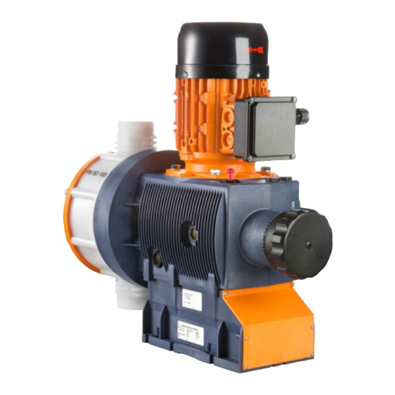
Diaphragm motor-driven metering pump
Sigma/ 2 Basic type S2Ba
EN
P_SI_0074_SW
Target group: Minimally instructed personnel
Please carefully read these operating instructions before use. · Do not discard.
The operator shall be liable for any damage caused by installation or operating errors.
The latest version of the operating instructions are available on our homepage.
Part no. 985908
Original operating instructions (2006/42/EC)
Version: BA SI 107 07/22 EN
Advertisement
Table of Contents

Related Manuals for ProMinent Sigma S2Ba


Summary of Contents for ProMinent Sigma S2Ba
- Page 1 Operating instructions Diaphragm motor-driven metering pump Sigma/ 2 Basic type S2Ba P_SI_0074_SW Target group: Minimally instructed personnel Please carefully read these operating instructions before use. · Do not discard. The operator shall be liable for any damage caused by installation or operating errors. The latest version of the operating instructions are available on our homepage.
- Page 2 Supplemental directives Supplementary information Read the following supplementary information in its entirety! Should you already know this information, you will benefit more from referring to the operating instructions. The following are highlighted separately in the document: Enumerated lists Fig. 1: Please read! Operating guidelines ð...
-
Page 3: Table Of Contents
Table of contents Table of contents Identity code..................5 1.1 Explanation of the ATEX label..........6 Safety chapter................. 9 2.1 Markings and warning symbols..........9 2.2 Intended use................9 2.3 Personnel qualification............10 2.4 Safety information..............11 2.5 Isolating protective equipment..........13 2.6 Requirements if the motor is being installed independently.. - Page 4 Table of contents 15.5.2 Media temperatures............64 15.5.3 Air humidity..............65 15.6 Installation height..............65 15.7 Motor data................65 15.8 Stroke actuator..............66 15.9 Stroke control drive............. 66 15.10 Diaphragm rupture sensor..........66 15.11 Stroke sensor "Sigma"............67 15.12 Relays................67 15.13 Gear oil................
-
Page 5: Identity Code
Union nut and PVDF hose sleeve Union nut and SS hose sleeve Union nut and SS welding sleeve Aseptic clamp fitting DIN 11864-3 (Standard for hygienic design) Design with ProMinent-Logo (standard) without ProMinent logo modified, order-specific design, see order paperwork for pump features... -
Page 6: Explanation Of The Atex Label
Identity code S2Ba Sigma 2 Basic type Electric power supply Connection data - see motor nameplate 3-phase, 230/400 V, 50/60 Hz 3-phase, 230/400 V, 50/60 Hz, with PTC Speed control motor, 3-phase 230/400 V, 50 Hz, with PTC no motor, with B14 flange, size 71 (DIN) no motor, with C 42 flange (NEMA) no motor, with B 5, size 56 (DIN) Degree of protection... - Page 7 Identity code Explanation of the pump’s ATEX labelling Sigma/ 2 for explosion group IIB gas - refer to your explosion protection document Temperature class for Temperature class T3 gas - refer to your explosion protection document for Temperature class T4 gas - refer to your explosion protection document Equipment protection level (EPL) high EPL...
- Page 8 Identity code Tab. 1: Example of the division of gases into explosion groups and temperature classes 85 °C 100 °C 135 °C 200 °C 300 °C 450 °C Carbon disulphide Trichlorosilane Ethyne Hydrogen Ethyl ether Ethene Mains gas (coal gas) Acetaldehyde Benzine, Ethanol,...
-
Page 9: Safety Chapter
Safety chapter Safety chapter These operating instructions include notes and extracts from German reg‐ ulations relating to the operator's scope of responsibility. The notes and quotes do not in any way release the operator from his/her responsibility as operator. The notes and quotes are only intended to remind the oper‐ ator or make them aware of specific problem areas. -
Page 10: Personnel Qualification
Observe the general limitations with regard to viscosity limits, chem‐ ical resistance and density - see also the ProMinent Resistance List (in the Product Catalogue or at www.prominent.com)! All other uses or modifications are prohibited. -
Page 11: Safety Information
ProMinent or another authorised distribution partner. Service Service refers to service technicians who have received certified training and have been authorised by ProMinent to work on the system. 2.4 Safety information Safety information WARNING! - Page 12 – Take into account the resistance of the wetted mate‐ rials and the ProMinent Resistance List when selecting the feed chemical - see the ProMinent Product Catalogue or visit ProMinent. WARNING! Danger of injury to personnel and material damage The pump must only be opened at those points required to be opened by these operating instructions.
-
Page 13: Isolating Protective Equipment
Safety chapter CAUTION! Danger from incorrectly operated or inadequately main‐ tained pumps Danger can arise from a poorly accessible pump due to incorrect operation and poor maintenance. – Ensure that the pump is accessible at all times. – Adhere to the maintenance intervals. Information in the event of an emergency In the event of an electrical accident, disconnect the mains cable from the mains/power supply or press the emergency cut-off switch fitted on the... -
Page 14: Safety Information For Atex Designs
Safety chapter As you have converted an "incomplete machine" into a complete machine, you must perform a conformity assessment, risk assess‐ ment, create a Declaration of Conformity, fit a company name‐ plate, ..Complete the pump documentation / operating instructions. Sound pressure level Sound pressure level LpA <... -
Page 15: Atex Safety Information
Safety chapter completed a relevant course of study or have a comparable technical qualification or another technical qualification combined with long-term experience of safety technology. The person must have knowledge of the relevant body of standards and regulations and have worked in the field for at least one year. The person needs to have opportunities for an exchange of experiences. - Page 16 Safety chapter Ignition hazard Protective measures to be observed by the customer Excessive surface pressure Limitation of the maximum temperature of the feed chem‐ ical Too low ambient temperature Limitation of the minimum ambient temperature Pump running hot The customer must monitor and maintain the pump in accordance with the “Maintenance”...
- Page 17 Safety chapter Ignition hazard Protective measures to be observed by the customer Ignition hazard with bought-in motor components Refer to the documentation for the motor. Comply with the monitoring intervals. The insulation resistance needs to be greater then 5 MOhm. Provide a time-delay residual current device.
- Page 18 Safety chapter WARNING! ATEX pump and flammable media The ignition temperature is reduced significantly below the ignition temperature at atmospheric pressure due to compression with the discharge stroke of the possibly ignitable vapour-air mixture. – Only use pumps with electrically conductive dosing heads.
-
Page 19: Potential Equalisation Lines And Other Features
Safety chapter WARNING! The following applies in areas at risk from explosion: – Note the details of the type examination certificate PTB 00 ATEX 2048 X for the Namur sensor NJ1.5-8GM-N as well. WARNING! ATEX pumps in areas at risk from explosion –... -
Page 20: Atex Features
WARNING! Stop the pump immediately in the event of any anoma‐ lies when inspecting the pump and rectify them immedi‐ ately. ProMinent Service may be needed if required. 2.7.5 ATEX features Maintenance Interval Maintenance work After 18,000 operating hours or 23,500 oper‐... -
Page 21: Safety Equipment
Safety chapter WARNING! Check after 1 day whether the oil drainage plug (2) is still tight. Power end and motor - ATEX Data Value Unit Ambient temperature during operation: -10 ... +40 °C TTT - ATEX liquid end Data Value Unit Max. -
Page 22: Explanation Of The Atex Label
Safety chapter Assembly of the motor - with designs without motor WARNING! The following instructions relevant in areas at risk from explosion apply in areas at risk from explosion. Select a suitable motor - the motor must correspond to the data for one of the motors from the “Motor data”... - Page 23 Safety chapter Explanation of the pump’s ATEX labelling Sigma/ 2 normal EPL use possible in zone 2 - refer to your explosion protection document Suffix X Special conditions - refer to the Declarations of Conformity and EC-type examination certificates WARNING! Example of EX-designation: Where may I use the ATEX version of the Sigma/ 2? The pump designation is:...
- Page 24 Safety chapter WARNING! Example 2 - EX-designation: Where may I use the ATEX version of the Sigma/ 2? The pump designation is " ... II 2G Ex h IIC T4 Gb X". The pump label corresponds to “Unit group” II: the pump may only be used in overground production systems, which are not at risk from firedamp.
-
Page 25: Storage, Transport And Unpacking
The "Decontamination Declaration Form" can be found at www.prominent.com. CAUTION! Danger of material damage The device can be damaged by incorrect or improper storage or transportation! –... -
Page 26: Overview Of Equipment And Control Elements
Overview of equipment and control elements Overview of equipment and control elements P_SI_0068_SW Fig. 3: Overview of equipment and control elements S2Ba Drive motor Drive unit Stroke length adjustment knob Liquid end with relief valve Diaphragm rupture sensor P_SI_0088_SW_2 Fig. 4: Sigma control elements Relief valve Diaphragm rupture sensor (visual) - Page 27 Overview of equipment and control elements P_SI_0095_SW Fig. 5: Adjusting the stroke length 100% = 4 rotations 25 % = 1 rotation 0.5 % = 1 scale mark on stroke adjustment dial PG11 P_SI_0036 Fig. 6: Front cover for version with pacing relay Pacing relay cable Supply voltage cable for pacing relay PCB...
-
Page 28: Functional Description
Functional description Functional description 5.1 Pump The metering pump is an oscillating diaphragm pump, the stroke length of which is adjustable. An electric motor drives the pump. 5.2 Liquid end The diaphragm (2) hermetically shuts off the pump volume of the dosing head (4) towards the outside. -
Page 29: Multi-Layer Safety Diaphragm
Functional description P_SI_0019 Fig. 8: Integral relief valve Spring, large Ball Rotary dial Spring, small Hose connection 5.4 Multi-layer safety diaphragm With visual diaphragm rupture sensors, in the event of a diaphragm rup‐ ture, the lowered red cylinder (6) springs forward beneath the transparent cover (7) so that it then becomes clearly visible - see Fig. -
Page 30: Assembly
Assembly Assembly Compare the dimensions on the dimensional drawing with those of the pump. 6.1 Assembly of the motor - with designs without motor Select a suitable motor. The motor must correspond to the data for one of the motors from the "Motor data" table - see Chapter "Tech‐ nical Data". -
Page 31: Base
Assembly Model size Motor flange B 5/140 * (26) Dimensions in mm - unless otherwise indicated. * Motor is fitted directly onto the motor flange without intermediate flange and claw coupling. 6.2 Base The pump can break through the base or slide off it Ensure that the base is horizontal, flat and permanently load-bearing. -
Page 32: Fastening
Assembly 6.4 Fastening Liquid end alignment Dosing rate too low. The valves of the liquid end cannot close correctly if the valves of the liquid end are not upright. Ensure that the discharge valve is upright. Vibrations can disturb the liquid end valves. Secure the metering pump so that no vibrations can occur. -
Page 33: Installation, Hydraulic
Installation, hydraulic Installation, hydraulic Disregarding the technical data during installation can lead to personal injury or damage to property. Observe the technical data - refer to the Chapter "Technical data" and, where applicable, the operating instructions for the accessories. WARNING! ATEX pumps in areas at risk from explosion –... - Page 34 The pump is supplied with PTFE moulded composite seals with a flare, which are used for the pump connectors, and which seal the connectors between grooved pump valves and ProMinent grooved inserts - see Fig. 15. Use an elastomer flat seal in the event that an unflared insert is used (e.g.
- Page 35 Installation, hydraulic CAUTION! Danger due to incorrect use of the integral relief valve The integral relief valve can only protect the motor and the gear, and then only against impermissible positive pressure that is caused by the metering pump itself. It cannot protect the system against positive pressure.
-
Page 36: Basic Installation Notes
Installation, hydraulic 7.1 Basic installation notes Safety information Rupturing hydraulic components Hydraulic components can rupture if the maximum permissible oper‐ ating pressure of the hydraulic parts is exceeded. Never allow the metering pump to run against a closed shut-off device. With metering pumps without integral relief valve: Install a relief valve in the pressure line. -
Page 37: Installation, Electrical
Never change the “Motor voltage” and “Cycle frequency” parameters with motor designs with integral frequency converter. The parameters on delivery from ProMinent do not correspond to the motor manufacturer’s factory settings. If other parameters are to be changed, then we recommend speaking to... - Page 38 Installation, electrical What requires electrical installation?: Motor External fan (optional) Stroke control drive (optional) Stroke adjusting drive (optional) Diaphragm rupture sensor (optional) Stroke sensor (optional) Pacing relay (option) Frequency converter (optional) Earthing wires (to be provided on site) Potential equalisation line (to be provided on site, prescribed in the area at risk from explosion) Motor ATEX pumps in areas at risk from explosion...
- Page 39 For further information on the motor with identity – code specification "S", refer to our website www.prominent.com. Motor data sheets can be requested for all other motors. With motors other than those with identity code –...
- Page 40 Installation, electrical Stroke sensor (identity code specification "Stroke sensor": 3) Connect the stroke sensor to a suitable monitoring device according to the technical data provided with the monitoring device and that of the stroke sensor - see chapter "Technical data". Make sure that the monitoring/feed equipment installed by the cus‐...
- Page 41 Installation, electrical Earthing lines Connect the electrical components of the entire installation supplied cleanly and permanently to an electrically clean earthing point, e.g. with an earthing bar on site - see earthing diagrams in the appendix. Potential equalisation lines, required in The entire installation supplied is provided ex works with the necessary areas at risk from explosion potential equalisation lines.
-
Page 42: Start Up
Start up Start up Safety information WARNING! ATEX pumps in areas at risk from explosion – Make sure that a suitably competent person checks whether the appropriate installation information from the "Installation" chapter has been implemented cor‐ rectly. – Make sure that a "recognised competent person" checks the electrical installation and in particular the intrinsically safe power circuits. - Page 43 Start up Diaphragm rupture sensor Unnoticed diaphragm rupture If the pump has been ordered with an electric diaphragm rupture sensor, then the diaphragm rupture sensor must also be installed. Screw the enclosed diaphragm rupture sensor into the liquid end. Unnoticed diaphragm rupture From approx.
- Page 44 Start up Using the integral relief valve CAUTION! Danger due to incorrect use of the integral relief valve The integral relief valve can only protect the motor and the gear, and then only against impermissible positive pressure that is caused by the metering pump itself. It cannot protect the system against positive pressure.
- Page 45 Start up Auxiliary equipment Check for the correct function of the auxiliary equipment and for correct interplay.
-
Page 46: During Operation
During operation During operation WARNING! Personnel injury and material damage may occur During use all units, protective equipment, additional devices must be fitted, operational and tightly closed. WARNING! Sparking caused by dry running If the bearings in the power end run dry, sparks can be formed. -
Page 47: Maintenance
Maintenance Maintenance 11.1 Safety information ATEX pumps in areas at risk from explosion Carry out a general check to ensure that the system is working prop‐ erly, particularly the power end and bearings, by regular monitoring (for leaks, noises, temperatures, smell ...). Do not allow the pump to run hot due to a lack of oil. -
Page 48: Inspection, Daily
WARNING! In the area at risk from explosion: Stop the pump safely and as quickly as possible and rectify these anomalies. ProMinent Service may be needed if required. 11.3 Standard liquid ends Under heavy loading (e.g. continuous operation) shorter maintenance intervals are recommended than those given. - Page 49 Maintenance Check the condition of the metering dia‐ The diaphragm is a wearing part, the service life of which is dependent on phragm the following parameters: System back pressure Operating temperature Feed chemical properties The diaphragm service life is reduced when using abrasive feed chemi‐ cals.
- Page 50 Maintenance WARNING! Only in areas at risk from explosion: Check after 1 day whether the oil drainage plug (2) is still tight.
-
Page 51: Repair
Only use original spare parts. Use the correct spare parts kits. If in doubt, refer to the exploded views and order information in the appendix or on our website www.prominent.com. Only with "Physiologically safe" design: WARNING! Product can be dangerously contaminated Only use the spare parts from the "Physiologically safe"... - Page 52 Repair CAUTION! Warning of feed chemical spraying around PTFE seals, which have already been used / com‐ pressed, can no longer reliably seal a hydraulic connec‐ tion. – New, unused PTFE seals must always be used. P_SI_0013_SW Fig. 22: Ball valve, simple, cross-section Flat seal Valve body Valve ball...
-
Page 53: Replacing The Diaphragm
Only use original spare parts. Use the correct spare parts kits. If in doubt, refer to the exploded views and order information in the appendix or on our website www.prominent.com. Personnel: Technical personnel Requirements: Put in place protective measures, if necessary. - Page 54 Should this not work, remove dirt or swarf from the thread and screw the diaphragm correctly onto the drive axle this time. ð If this is still unsuccessful, contact ProMinent-ProMaqua Service. Place the dosing head with the screws onto the diaphragm - the suction connector should be pointing downwards when the pump is subsequently installed.
- Page 55 Repair Optical diaphragm rupture sensor Unscrew the transparent cover from the diaphragm rupture sensor. Press the red cylinder into the diaphragm rupture sensor until the cylinder engages. Press the piston on the other side of the diaphragm rupture sensor into the dosing head (approximately 4 mm) using a blunt, smooth object until it triggers.
- Page 56 Repair P_SI_0038 Fig. 25: Cross-section through the liquid end Suction valve Diaphragm Discharge valve Dosing head Backplate 13 Safety diaphragm...
-
Page 57: Troubleshooting
Troubleshooting Troubleshooting Before commencing all work WARNING! Danger from hazardous substances! Possible consequence: Fatal or very serious injuries. Please ensure when handling hazardous substances that you have read the latest safety data sheets provided by the manufacture of the hazardous substance. The actions required are described in the safety data sheet. - Page 58 All other faults. Other causes. Call ProMinent Service. * If necessary use the cross-section drawing of the integral relief valve in the "Functional Description" chapter. WARNING! Warning of eye injuries When opening the relief valve, a spring under high ten‐...
- Page 59 Troubleshooting Leaking feed chemical When dosing combustible feed chemicals or in areas at risk from explosion, under no circumstances must the second diaphragm also rupture. If the diaphragm rupture sensor triggers, stop the pump safely and as quickly as possible. Only restart the pump once a new multi-layer safety diaphragm is fitted.
-
Page 60: Decommissioning
Decommissioning Decommissioning Before commencing all work WARNING! Danger from hazardous substances! Possible consequence: Fatal or very serious injuries. Please ensure when handling hazardous substances that you have read the latest safety data sheets provided by the manufacture of the hazardous substance. The actions required are described in the safety data sheet. - Page 61 Decommissioning (Temporary) decommissioning Disconnect the pump from the mains/power supply. Depressurise and vent the hydraulic system around the pump. Drain the liquid end by turning the pump upside down and allowing the feed chemical to run out. Flush the liquid end with a suitable medium, observing the material safety data sheet.
-
Page 62: Technical Data
Technical data Technical data Only with "M - modified" design: WARNING! Risk of personal injuries Please observe the ”Supplement for modified version“ at the end of the chapter! It replaces and supplements the technical data! 15.1 Performance data S2Ba at 50 Hz operation Type Minimum pump capacity at max‐... -
Page 63: Viscosity
Technical data S2Ba at 60 Hz operation Type Minimum pump capacity at maximum back pres‐ Maximum Suction lift Permissible Connector sure stroke priming size rate pressure, suction side Strokes/mi m water R"-DN column 16050 PVT 15.9 1" - 15 16050 SST 14.8 1"... -
Page 64: Shipping Weight
Technical data 15.3 Shipping weight Types Material version Shipping weight 16050 ... 16130 PVT, TTT 07120 ... 04350 PVT, TTT 15.4 Wetted materials Material ver‐ Liquid end Suction/pres‐ Seals* / ball Balls Springs Integral relief sion sure connector seat valve PVDF PVDF PTFE / PTFE... -
Page 65: Air Humidity
Technical data Liquid end SST, SSF Data Value Unit Max. temperature, long-term at max. oper‐ 90 °C ating pressure Max temperature, for 15 minutes at max. 2 120 °C* Minimum temperature. -10 °C * not in areas at risk from explosion 15.5.3 Air humidity Air humidity... -
Page 66: Stroke Actuator
For further information on the motor with identity – code specification "S", refer to our website www.prominent.com. Motor data sheets can be requested for all other motors. With motors other than those with identity code –... -
Page 67: Stroke Sensor "Sigma
Technical data 5–25 V DC, in accordance with Namur or DIN 60947-5-6, potential-free design. Data Value Unit Nominal voltage * 8 V DC Power consumption - active surface > 3 mA uncovered Power consumption - active surface cov‐ < 1 mA ered Rated switching distance 1.5 mm... -
Page 68: Gear Oil
Technical data 15.13 Gear oil Manufac‐ Name Viscosity Order no. Oil volume, Oil volume, turer class supplied needed (ISO approx. 3442) Mobil Mobil VG 460 1004542 1.0 l 0.55 l Gear 634 * or comparative gear oil 15.14 Sound pressure level Sound pressure level Sound pressure level LpA <... -
Page 69: Diagrams For Setting The Metering Capacity
Diagrams for setting the metering capacity Diagrams for setting the metering capacity S2Ba (50 Hz) S2Ba (60 Hz) C [l/h] C [l/h] 04350 07220 04350 07120 07220 16130 07120 16090 16130 16050 16090 16050 S [%] S [%] C [l/h] C [l/h] 04350 07220... -
Page 70: Dimensional Drawings
Dimensional drawings Dimensional drawings Compare the dimensions on the dimension sheet – and pump. All dimensions are in mm. – Dimension sheet for S2Ba Ø165 max.40 P_SI_0050_SW 61_01-101_00_27-73_1 Fig. 27: Dimensions in mm - diagram is not binding. Tab. 8: Dimensions in mm Type Connector ØG... - Page 71 Dimensional drawings Dimension sheet S2Ba, servomotor and motor flange P_SI_0054_SW_2 61_01-101_00_27-73 Fig. 28: Dimensions in mm - diagram is not binding. Motorflansch ØP ØM ØN ØS ØD motor flange B 14/105 16.3 56 C/138 5.43" 5.88" 4.5" 0.43" 0.62" 1.14" 0.16"...
-
Page 72: Potential Equalisation Drawings For Sigma Basic Type
Potential equalisation drawings for Sigma Basic Type Potential equalisation drawings for Sigma Basic Type P_SI_0170_SW Fig. 29: Potential equalisation drawing for Sigma S2Ba Potential equalisation of motor Potential equalisation of motor flange Potential equalisation of liquid end Potential equalisation of diaphragm rupture indicator Potential equalisation of stroke sensor Positions 1, 2 and 5 must be connected to a protective earth cable. -
Page 73: Motor Data Sheet Standard Motor
* upon request at manufacturer observation * sur demande auprès du producteur ProMinent Pumpentyp S2BaHM _ _ _ _ _ _ _ _ _ _ _ _ S _ _ _ S2CaHM _ _ _ _ _ _ _ _ _ _ _ _ U _ _ _ _ _ _... -
Page 74: Exploded Drawings For Sigma/ 2
Exploded drawings for Sigma/ 2 Exploded drawings for Sigma/ 2 Liquid end Sigma/ 2 130-DN 15 and 350- DN 25 PVT P_SI_0024 Fig. 30: Liquid end Sigma/ 2 130-DN 15 and 350-DN 25 PVT Pos. Description Type 16050, 16090, Type 04350, 07120, 16130 07220 Spring... - Page 75 Exploded drawings for Sigma/ 2 Sigma/ 2 PVA relief valve-A P_SI_0086_SW Fig. 31: Sigma/ 2 PVA relief valve-A Pos. Description Type 16050, Type 07120, Type 04350, 16090, 16130 07220 Relief valve, complete 10 bar PVA 1018947 Relief valve, complete 7 bar PVA 740811 Relief valve, complete 4 bar PVA 740812...
- Page 76 Exploded drawings for Sigma/ 2 Liquid end for Sigma/ 2 130 and 350 TTT P_SI_0176_SW Fig. 32: Liquid end for Sigma/ 2 130 and 350 TTT Pos. Description Type 16050, 16090, Type 04350, 07120, 16130 07220 Spring Ball Ball seat Diaphragm rupture sensor, optical 1033323 1033323...
- Page 77 Exploded drawings for Sigma/ 2 Liquid end for Sigma/ 2 130 and 350 SST P_SI_0025_SW Fig. 33: Liquid end for Sigma/ 2 130 and 350 SST Pos. Description Type 16050, 16090, Type 04350, 07120, 16130 07220 Spring Ball Ball seat Diaphragm rupture sensor, optical 1033323 1033323...
- Page 78 Exploded drawings for Sigma/ 2 Sigma/ 2 SSA relief valve-A P_SI_0087 Fig. 34: Sigma/ 2 SSA relief valve-A Pos. Description Type 16050, Type 07120, Type 04350, 16090, 16130 07220 Relief valve, complete 16 bar SSA 1019246 Relief valve, complete 7 bar SSA 740815 Relief valve, complete 4 bar SSA 740814...
-
Page 79: Wear Parts Of Sigma/ 2
Wear parts of Sigma/ 2 Wear parts of Sigma/ 2 Scope of delivery: - see exploded drawings. 21.1 Standard Tab. 9: Spare parts kits types 16050, 16090, 16130 Liquid ends Wetted materials Remark Order no. FM 130 - DN15 1046472 FM 130 - DN15 1077573 FM 130 - DN15... - Page 80 Wear parts of Sigma/ 2 Tab. 14: Spare parts kits PVF (liquid ends) Liquid end Types 16050, 16090, 16130 Types 07120, 07220, 04350 FM 130 - DN 15 1046472 FM 350 - DN 25 1046475 Tab. 15: Spare parts kits SSF (liquid ends) Liquid end Types 16050, 16090, 16130 Types 07120, 07220, 04350...
-
Page 81: Declaration Of Conformity For Machinery
In accordance with DIRECTIVE 2006/42/EC OF THE EUROPEAN PAR‐ LIAMENT AND OF THE COUNCIL, Appendix I, BASIC HEALTH AND SAFETY REQUIREMENTS, section 1.7.4.2. C. ProMinent GmbH Im Schuhmachergewann 5 - 11 D - 69123 Heidelberg, Germany, hereby declare that the product specified below complies with the relevant basic health and safety requirements of the Directive, on the basis of its functional concept and design and in the version distributed by us. -
Page 82: Declaration Of Incorporation For Machinery
In accordance with DIRECTIVE 2006/42/EC OF THE EUROPEAN PAR‐ LIAMENT AND OF THE COUNCIL, Appendix I, BASIC HEALTH AND SAFETY REQUIREMENTS, section 1.7.4.2. C. ProMinent GmbH Im Schuhmachergewann 5 - 11 D - 69123 Heidelberg, Germany, hereby declare that the product specified below complies with the relevant basic health and safety requirements of the Directive, on the basis of its functional concept and design and in the version distributed by us. -
Page 83: Declaration Of Conformity For Atex Machinery
Declaration of Conformity for ATEX Machinery Declaration of Conformity for ATEX Machinery For pumps with explosion protection: ProMinent GmbH Im Schuhmachergewann 5 - 11 DE - 69123 Heidelberg, Germany, hereby declare that the product specified below complies with the relevant basic health and safety requirements of the Directive, on the basis of its functional concept and design and in the version distributed by us. -
Page 84: Declaration Of Conformity For Atex Machinery
In accordance with DIRECTIVE 2006/42/EC OF THE EUROPEAN PAR‐ LIAMENT AND OF THE COUNCIL, Appendix I, BASIC HEALTH AND SAFETY REQUIREMENTS, section 1.7.4.2. C. ProMinent GmbH Im Schuhmachergewann 5 - 11 D - 69123 Heidelberg, Germany, hereby declare that the product specified below complies with the relevant basic health and safety requirements of the Directive, on the basis of its functional concept and design and in the version distributed by us. -
Page 85: Index
Index Index Identity code ......5 Identity code versions for areas at risk from explosion Actuator . - Page 86 Index Start up ....... . . 42 Storage ....... . . 25 Storage and transport temperature .
- Page 88 ProMinent GmbH Im Schuhmachergewann 5-11 69123 Heidelberg Germany Telephone: +49 6221 842-0 Fax: +49 6221 842-419 Email: info@prominent.com Internet: www.prominent.com 985908, 5, en_GB © 2022...
Need help?
Do you have a question about the Sigma S2Ba and is the answer not in the manual?
Questions and answers