Table of Contents
Advertisement
Quick Links
CAUTION: U.S. Federal law restricts this device to sale by or on the order of a licensed medical practitioner.
Datex-Ohmeda, Inc.
P.O. Box 7550
Madison, WI 53707-7550, USA
Tel. +1-608-221-1551
Fax +1-608-222-9147
TM
S/5
Light Monitor, F-LM1, F-LMP1
Technical Reference Manual
All specifications are subject to change without notice.
Outside the USA, check local laws for any restriction that may apply.
www.datex-ohmeda.com www.gehealthcare.com
© 2005 Copyright General Electric Company
Datex-Ohmeda
Order Code M1037863
October 2005
Healthcare Finland Oy
Helsinki, Finland
P.O. Box 900
FIN-00031 GE, FINLAND
Tel: +358 10 39411
Fax : +358 9 146 3310
Advertisement
Chapters
Table of Contents
Troubleshooting

Subscribe to Our Youtube Channel
Related Manuals for Datex-Ohmeda F-LM1


Summary of Contents for Datex-Ohmeda F-LM1
- Page 1 Datex-Ohmeda Light Monitor, F-LM1, F-LMP1 Technical Reference Manual All specifications are subject to change without notice. CAUTION: U.S. Federal law restricts this device to sale by or on the order of a licensed medical practitioner. Outside the USA, check local laws for any restriction that may apply.
- Page 2 Intended purpose Datex-Ohmeda S/5 Light Monitor, F-LM1, F-LMP1 is intended for stationary and mobile monitoring of patient’s ECG, SpO2, body temperature, invasive and non-invasive blood pressures as well as respiration and CO2 in hospitals and ambulances. When used outdoors, the monitor must be in the protective case. The monitor is intended for use by qualified medical personnel only.
- Page 3 Unit 8000060-1 Isolation Power Supply Unit for CO Unit Datex-Ohmeda Light Monitor Recorder, N-LREC 890201-5 Datex-Ohmeda Light Monitor Power Adapter, N-LPOW M1051340 Datex-Ohmeda Light Monitor Battery Module, F-LBAT 890200-5 Datex-Ohmeda Light External Battery Charger, N-LCHGR 896192-1 DataCard and Network Options, N-LDATA, N-LNET, N-LDNET...
- Page 4 Datex-Ohmeda S/5 Light Monitor Document No. M1037863...
-
Page 5: Table Of Contents
Table of contents TABLE OF CONTENTS PART 1 - GENERAL SERVICE GUIDE TABLE OF CONTENTS Part 1 - General Service Guide TABLE OF FIGURES INTRODUCTION Notes to the reader..........................2 About this manual..........................2 Related documents ..........................2 Installation ............................3 1.4.1 Choosing the location ........................ - Page 6 Datex-Ohmeda S/5 Light Monitor 5.1.4 ECG board tests......................... 25 5.1.5 STP board tests ......................... 25 5.1.6 NIBP board test ......................... 26 5.1.7 Mainstream CO test........................26 Performance checks........................... 27 SERVICE CHECK General service information........................ 30 Service check procedure ........................30 6.2.1...
-
Page 7: Table Of Figures
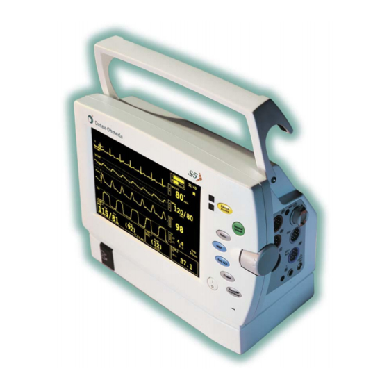
Table of contents 10.7 External power adapter........................57 10.8 Light External Battery Charger (optional)..................58 10.9 Output specifications ........................58 10.9.1 Nurse Call and Defibrillator Synchronization Signals..............58 APPENDICES FUNCTIONAL CHECK form SERVICE CHECK form EMC Guidance TABLE OF FIGURES Figure 1 S/5 Light Monitor with battery module and power adapter ..............1 Figure 2... - Page 8 Datex-Ohmeda S/5 Light Monitor Document No. M1051339...
-
Page 9: Introduction
The S/5 Light Monitor is a portable factory configurated compact monitor designed for stationary and mobile indoor monitoring of a patient’s vital signs. The monitor is available in two configurations; F-LM1 and F-LMP1. The difference between the configurations is illustrated in table 1. -
Page 10: Notes To The Reader
Datex-Ohmeda S/5 Light Monitor The following factory configurable parameters and functions are available: • N-LNET; Network option • N-LDATA; DataCard option • N- LDNET; Network and DataCard options • N-LCM; Mainstream CO option To all monitors following options are available: •... -
Page 11: Installation
Introduction 1.4 Installation 1.4.1 Choosing the location The monitor can be placed on a flat surface or hung with the handle from the bed or wall rails. Make sure that the surface or rail holds up to at least 10 kg/22 lb. 1.4.2 Warnings WARNING The monitor or its components should not be used adjacent to or stacked with... -
Page 12: Symbols
Datex-Ohmeda S/5 Light Monitor 1.5 Symbols 1.5.1 Symbols on equipment Attention, consult accompanying documents. on the rear panel Electric shock hazard. Do not open monitor frame. Refer servicing to qualified personnel. indicates the Do not touch any part of monitor or patient connections during defibrillation procedure. - Page 13 Introduction : Type BF (IEC-60601-1) protection against electrical shock, not defibrillation proof. : Type CF (IEC-60601-1) protection against electrical shock, not defibrillation proof. NIBP: Type BF (IEC-60601-1) defibrillator-proof protection against electrical shock. ECG, P : Type CF (IEC-60601-1) defibrillator-proof protection against electrical shock. Battery packs contain heavy metal cadmium (chemical symbol Cd) and, in case of disposal, must be separated from other waste according to local regulations.
-
Page 14: Symbols On Transport Packaging
Datex-Ohmeda S/5 Light Monitor IPX1 – vertically falling water drops shall have no harmful effects. IPX4 – splash proof SN, S/N Serial number Battery charging LEDs: LEDs will blink while batteries are being charged, and will stay illuminated when batteries are fully charged and the monitor is connected to mains. - Page 15 Introduction This symbol is to indicate the temperature limitations within which the transport package should be kept and handled. Document No. M1051339...
-
Page 16: Safety
Datex-Ohmeda S/5 Light Monitor SAFETY 2.1 Safety precautions 2.1.1 Warnings WARNING Indicates situations in which the user or the patient may be in danger of injury or death. Explosion hazard • Do not use the monitor in presence of flammable anesthetics. - Page 17 Safety Patient safety • Always make sure that necessary alarm limits are set and operative when you start monitoring. • When the alarms are suppressed, observe the patient frequently. • Connect only one patient to one monitor at a time. •...
- Page 18 Datex-Ohmeda S/5 Light Monitor WARNING Use only approved accessories, mounts and defibrillator-proof cables and invasive pressure transducers. For a list of approved supplies and accessories, see the Supplies and Accessories catalog. Other cables, transducers and accessories may cause a safety hazard, damage the equipment or system, result in increased emissions or decreased immunity of the equipment or system or interfere with the measurement.
-
Page 19: Cautions
Indicates situations in which the unit or devices connected to it may be damaged. • Use licensed patient cables and accessories only, see Datex-Ohmeda Catalogue Patient Monitor Supplies and Accessories. Other cables and accessories may damage the system or interfere with measurement. -
Page 20: Esd Precautionary Procedures
Datex-Ohmeda S/5 Light Monitor Storage and transport • For allowed storage and transport conditions refer to the documentation delivered with the monitor. Points to note • Medical electrical equipment needs special precautions regarding electromagnetic compatibility and needs to be installed and put into service by qualified personnel according to the electromagnetic compatibility information provided in the Appendix C. -
Page 21: Safety Test
Safety 2.3 Safety test Measure leakage current according to following procedures: • Connect the GND electrode of the test device to the body of the 9-pin D-connector of the Light Monitor. The nuts that are for locking the male cable connector can be used as well. Document No. -
Page 22: Architecture
Datex-Ohmeda S/5 Light Monitor ARCHITECTURE The Light Monitor is a compact patient monitor with fixed configuration. The monitor is designed for stationary and mobile indoor monitoring of a patient’s vital signs. The monitor can be equipped with an optional recorder and battery module. An external power adapter is provided for power supply. - Page 23 Architecture STP unit The STP unit is a parameter board that measures invasive blood pressure(s), body temperature and oxygen saturation of the blood (SpO2). ECG unit The ECG unit is a parameter board that measures 3-lead ECG. NIBP unit The NIBP unit is a parameter board that measures non-invasive blood pressure. unit The CO unit measures carbon dioxide consentration of the respiration gases.
-
Page 24: Power Supply Unit
Datex-Ohmeda S/5 Light Monitor 3.2 Power supply unit The power supply board functions can be summarized as follows: • Charge the batteries. • Choose between battery and mains operation. • Distribute power to the CPU, CO , STP, ECG, and NIBP boards. -
Page 25: Nibp Unit
Architecture 3.4 NIBP unit The NIBP unit consists of the NIBP board, an air pump, and pneumatic valves. The NIBP board functions can be summarized as follows: • Control the function of the air pump and the pneumatic valves. • Measure the pressure variation of the NIBP cuff. -
Page 26: Display Unit
3.10.1 Module bus The module bus is an asynchronous, CMOS-level serial communication between host processor and Datex-Ohmeda based parameter modules and CO measurement by Welch Allyn. Only TXDM and RXDM signals are used. The TXDM signal is module bus transmit line from host to modules and the RXDM signal is a receive line from modules to host. -
Page 27: Co Module
Architecture 3.10.3 CO module The CO module, manufactured by Welch Allyn is used in the Light Monitor for CO mainstream measurement. Communication with the host is provided by an asynchronous serial link. Signals used in the communication are TXDC, RXDC. The TXDC signal is transmit line from host to CO module and the RXDC signal is a receive line from CO module to host. -
Page 28: Cleaning
Datex-Ohmeda S/5 Light Monitor CLEANING Before cleaning: • Turn the power to Standby • Disconnect the power cord from the mains power supply After cleaning: • Let dry completely • Reconnect the power cord and turn the power ON CLEANING CASING /... -
Page 29: Functional Check
Functional check FUNCTIONAL CHECK These instructions include complete procedures for functional check (FC) for Datex-Ohmeda Light Monitors. The functional check is recommended to be performed after monitor installation and after long storage. The first part of the instructions contains check procedures that are done through the service menu. - Page 30 Datex-Ohmeda S/5 Light Monitor Switch the monitor on. Check that the monitor starts up properly, i.e. − both alarm LED’s turn on and off − the fan starts running − the start-up sound is heard from the loudspeaker − the normal monitoring screen appears −...
-
Page 31: Recorder Test
Functional check Reconnect the power cord and check that during charging, the charging symbol is displayed and the Battery charge status LED starts flashing: 5.1.1 Recorder test Open the paper compartment cover. Check that the message “Recorder: Cover open” appears on the screen, then close the cover. Select Main Menu - Record/Print- Record Wave and check that the recorder starts recording. -
Page 32: Network Test
5.1.3 Network test Connect the Mon-Net cable and the Identification plug to the monitor. Check that the monitor connects to the Datex-Ohmeda Network, i.e. the network symbol is displayed on the upper right-hand corner of the screen. A message regarding the connection to Datex-Ohmeda Information Center should appear in the message field on the screen. -
Page 33: Ecg Board Tests
Functional check 5.1.4 ECG board tests Enter the ESTP : ECG service menu: Menu Press the button and select: Monitor Setup - Install/Service (Password 16-4-34) - Service View (Password 26-23-8) - Modules - ESTP : ECG Check from the Service Data that: −... -
Page 34: Nibp Board Test
Datex-Ohmeda S/5 Light Monitor 5.1.6 NIBP board test Enter the NIBP service menu: Check that the “Timeouts”, “Bad checksums” and “Bad c-s by mod” values are not increasing faster than by 50 per second. Check that the NIBP board memories have passed the internal memory test, i.e. “RAM”, “ROM”... -
Page 35: Performance Checks
Functional check 5.2 Performance checks Connect a 5-lead cable to the monitor. Configure the monitor screen so that all parameter information is displayed, for example for the maximum configuration: Menu Press the button to enter the Main Menu and select: Monitor Setup - Waveform Fields/Digit Fields Waveform Fields Digit Fields... - Page 36 Datex-Ohmeda S/5 Light Monitor Connect the patient simulator to the ECG and InvBP connectors, SpO probe to the SpO connector and temperature test plug to the Temp connector. Attach the SpO probe on your finger and check that: − the simulated waveforms are good −...
- Page 37 Functional check Check that the message “No CO2 sensor” is displayed when there is no CO sensor connected. Connect a CO sensor to the monitor and check that the message “warming” is displayed. Wait until the “warming” message disappears and the CO value appears on the screen.
-
Page 38: Service Check
Datex-Ohmeda S/5 Light Monitor SERVICE CHECK 6.1 General service information Field service of the Light Monitor is limited to replacing faulty printed circuit boards or mechanical parts. Faulty printed circuit boards should be returned to GE Healthcare for repair. GE Healthcare is always available for service advice. Please provide the unit serial number, full type designation, and a detailed description of the fault. -
Page 39: Visual Inspection
Service check Tool Order No. CO2 option) Mainstream CO2 airway adapter (only for monitors 902301/902302/ with CO2 option) 902303 Screwdriver -Pozidrive- type MemCard- Data (only for monitors with data card option) Recommended parts Part Order No. Notes Fan filter 886841 Recorder paper 74205 if N-LREC option... - Page 40 Datex-Ohmeda S/5 Light Monitor Figure 2 Adjustment trimmer R23 in N-LPOW − Clean or replace the fan filter. − Clean the recorder unit, if necessary. − Check that all shielding flaps (6 pcs) are properly closed. (Figure 3) Shielding Flaps...
- Page 41 Service check both screws on the patient panel are tightened properly − General functional inspection − Connect the power cord to the Power Adapter and the Power Adapter cable to the Light Monitor. Check that the green LED turns on in the power adapter and the LED on the lower right-hand corner of the monitor turns on or starts flashing.
- Page 42 Datex-Ohmeda S/5 Light Monitor Preset ECG, Respiration, InvBP and SpO measurement settings: ECG & Resp ECG Setup - Hr Source - Auto - Pacemaker - Show - Resp Setup - Size - 1.0 - Resp Rate Source - Auto - Measurement - On - Detection Limit - Auto NIBP &...
-
Page 43: Recorder Test
6.2.4 Network test Connect the Mon-Net cable and the Identification plug to the monitor. Check that the monitor connects to the Datex-Ohmeda Network, i.e. the network symbol is displayed on the upper right-hand corner of the screen. A message regarding the connection to Datex-Ohmeda Information Center should appear in the message field on the screen. -
Page 44: Ecg Measurement
Datex-Ohmeda S/5 Light Monitor 6.2.5 ECG measurement Enter the service menu: Menu - Monitor Setup - Install/Service (Password 16-4-34) - Service View (Password 26-23-8) Take down the information regarding monitor software and unit id by selecting Scroll Vers and turning the ComWheel or choose Record Vers if the recorder is installed. -
Page 45: Respiration Measurement
Service check Lead selection Lead to be detached Message Lead I L/LA Leads off R/RA Leads off N/LL Leads off Lead II L/LA Leads off R/RA Leads off N/LL Leads off Lead III L/LA Leads off R/RA Leads off N/LL Leads off Check that in any case the correspondence electrode (RA, LA or LL) shows off. - Page 46 Datex-Ohmeda S/5 Light Monitor RATIO - 1/1 APNEA - OFF SHIFT – OFF Check that the Resp waveform is shown and the RR value is 20 (±5). Change the position of the BASELINE IMPEDANCE -switch and check that appropriate RESP waveform and RR value are shown again within 30 seconds.
-
Page 47: Temperature Measurement
Service check 6.2.7 Temperature measurement Enter the ESTP : STP service menu: Modules - ESTP : STP Check that the “Timeouts”, “Bad checksums” and “Bad c-s by mod” values are not increasing faster than by 50 per second. Check also that the STP board memories have passed the internal memory test, i.e. -
Page 48: Spo 2 Measurement
Datex-Ohmeda S/5 Light Monitor Check the InvBP channels with a patient simulator. The settings and checks with Dynatech Nevada MedSim 300 Patient Simulator: SENSITIVITY -switch - 5 µV/V/mmHg ECG - BASE - BPM - 60 - BP - 1 - WAVE - ATM... -
Page 49: Non Invasive Blood Pressure Measurement
Service check 6.2.10 Non Invasive Blood Pressure measurement Enter the NIBP module service menu: Monitor Setup - Install/Service (Password 16-4-34) - Service (Password 26-23-8) - Modules - NIBP Check that the “Timeouts”, “Bad checksums” and “Bad c-s by mod” values are not increasing faster than by 50 per second. - Page 50 Datex-Ohmeda S/5 Light Monitor the displayed pressure value in order to determine the real pressure. Check the watchdog timer activation pressure. Select Pneumatics from the NIBP service menu. Keep the pressure manometer connected to the cuff connector. Pump up the pressure very slowly and note the value on the manometer when you hear a signal from the loudspeaker.
-
Page 51: Mainstream Co Measurement
Service check that the message “Cuff occlusion” appears on the screen within 30 seconds. Check that automatic inflation limits are in use: Menu – NIBP & Inv.Press - NIBP Setup&Alarm - Inflation Limits – Auto Previous Menu Connect the cuff onto your arm, highlight START VEN.STASIS in the NIBP & Inv.Press menu and press the ComWheel. -
Page 52: For Light Monitor
Datex-Ohmeda S/5 Light Monitor 6.2.12 For Light Monitor Perform electrical safety check and leakage current test. Check that the monitor functions normally after the performed electrical safety check. Clean the monitor with suitable detergent. • Fill in all necessary documents. -
Page 53: Adjustments And Calibrations
Adjustments and calibrations ADJUSTMENTS AND CALIBRATIONS 7.1 Pressure safety level detection “OFFSET” Check from the service view (Modules - NIBP) that AD0 = 0 ±1. If it is not: remove the back panel and adjust the trimmer located NIBP boards upper edge AD0 to zero. Pump up the pressure very slowly and check that the value of AD5 changes from negative value to positive value under pressure 11..15 mmHg. -
Page 54: Calibration
Datex-Ohmeda S/5 Light Monitor Pump the following pressures to manometer and check the difference between the manometer and monitor pressure display: Table 2 NIBP calibration check pressures Pressure Max. error Example 0 mmHg ±9 mmHg (=zero offset) 100 + zero offset ±2 mmHg 98 ±2... -
Page 55: Temperature Calibration
Adjustments and calibrations • Connect an external mercury manometer with pump to device through the both tubes of the hose - both transducers B1 and B2 must be calibrated simultaneously. Pump up to a pressure about 200 mmHg according to the manometer. Calibration is possible in the range 150 to 300 mmHg. -
Page 56: Invasive Pressure Calibration
Datex-Ohmeda S/5 Light Monitor Press the ComWheel two times. Press in the protect button at the bottom of the module and choose ON in protect mode. Release the button. 7.4 Invasive pressure calibration Calibrate invasive pressure when the pressure transducer (probe) is replaced with a different type of transducer, and when LM-STP board is replaced. -
Page 57: General Troubleshooting
General troubleshooting GENERAL TROUBLESHOOTING 8.1 Troubleshooting flowchart Monitor does not start Remove mains cable and batteries and switch monitor OFF Connect mains cable back and switch monitor Over voltage or over current protector triggered Fan is Check mains MAINS led running? cable lit? -
Page 58: Service Menu
Datex-Ohmeda S/5 Light Monitor SERVICE MENU 9.1 SW version / unit ID Software version and Unit ID are shown in the Service View menu. Menu Press key. Enter Monitor Setup - Install/Service (password 16-4-34) - Service View (password 26-23-8). Software strings have the following format: XXXX SW PPPPPP-N.N YYYY-MM-DD... -
Page 59: Language Selection
Service menu 9.2 Language selection Language can be selected in the Monitor menu. Menu Press key. Enter Monitor Setup - Install/Service (password 16-4-34) - Service View (password 26-23-8) - Monitor. 9.3 Monitor configuration Monitor configuration can be selected in the Monitor menu. Menu Press key. -
Page 60: General Specifications
Datex-Ohmeda S/5 Light Monitor GENERAL SPECIFICATIONS Safety standards Designed to meet IEC 60601-1 and CAN/CSA C22.2 No 601.1 10.1 Parameter specifications 10.1.1 ECG Measured leads: I, II or III Frequency response: 0.5...30 Hz (-3 dB, with 50 Hz reject filter) 0.5...40 Hz (-3 dB, with 60 Hz reject filter) -
Page 61: Pulse Oximetry (Spo 2 )/Pleth
2, 5, 10, 20, 50 mod % or automatic scaling Accuracy is based on deep hypoxia studies using Datex-Ohmeda Finger Sensors on volunteered subjects. Arterial blood samples have been analyzed by a Radiometer OSM Co-oximeter. Refer to Datex-Ohmeda Sat Sensor directions for specific SpO accuracy. -
Page 62: Non-Invasive Blood Pressure
Datex-Ohmeda S/5 Light Monitor 10.1.5 Non-invasive blood pressure Measurement principle: Oscillometric with linear deflation Deflation speed: Heart rate dependent, 5...13 mmHg/s Measurement range: Adult 25...260 mmHg child 25...190 mmHg infant 15...140 mmHg Pulse rate range: 30...250 bpm Measurement intervals: manual and selectable intervals 1, 2.5, 3, 5, 10, 15, 30, 60 min or... -
Page 63: Co (Option N-Lcm)
General specifications Transducer sensitivity: 5 µV/V/mmHg, 5 Vdc, max.20 mA Pressure filter: 22 Hz (-3 dB) for P1, Art 9 Hz (-3dB) for P2, CVP, PA, ICP 10.1.7 CO (option N-LCM) Principle of operation: Mainstream, non-dispersive infrared, single beam, single frequency, fully chopped, ratiometric Measurement range: 0-99 mmHg / 0-13 vol-% / 0-13 kPa... -
Page 64: Environmental Conditions
For accessories, please refer to the Supplies and Accessories catalogue. Specifications subject to change without notice. 10.3 Option codes Description Order code S/5 Light Monitor F-LM1 w/ ECG, Resp, NIBP, SpO , Temp S/5 Light Monitor F-LMP1 w/ ECG, Resp, NIBP, SpO , Temp, 2xIBP Light Monitor Power Adapter... -
Page 65: Trends
General specifications 10.4.2 Trends Graphical: 2, 4, 12 and 24 h Numerical: all parameters, sampled every 5 min and after NIBP measurement Trend cursor: Both in graphical and numerical trends 10.4.3 Alarms • Adjustable high and low alarms for HR, Resp, NIBP, SpO2, Temp, CO2 (Et/Fi) and Invasive Pressures Alarm system classified according to priority;... -
Page 66: Light External Battery Charger (Optional)
Datex-Ohmeda S/5 Light Monitor 10.8 Light External Battery Charger (optional) Mains voltage 100...240 VAC Max. input power 90 VA Mains frequency 50...60 Hz Charge current 1.7 A, ± 10 % Discharge current 0.6 A, ± 10 % Typical charging time 1 h per battery / 1.8 Ah... -
Page 67: Appendices
APPENDICES A-C APPENDICES APPENDIX A, Functional check form APPENDIX B, Service check form APPENDIX C, EMC Guidance Document No. M1051339... - Page 68 Datex-Ohmeda S/5 Light Monitor Document No. M1051339...
-
Page 69: Functional Check Form
FUNCTIONAL CHECK FORM Datex Ohmeda S/5 Light Monitor Customer Service Service engineer Date Monitor configuration Monitor model: F-LM1 Model with 2 InvBP measurements, F-LMP1 Parameter measurement options Data collecting and data management options N-LCM Mainstream CO N-LREC Recorder N-LNET Network... - Page 70 Datex-Ohmeda S/5 Light Monitor Performance checks N.A. Fail 1. Monitor screen configuration 2. SpO check 3. InvBP simulation 4. SpO : No probe and Probe off messages 5. SpO value (95-99 %) and HR value 6. SpO : No probe message 7.
-
Page 71: Service Check Form
SERVICE CHECK FORM Datex Ohmeda S/5 Light Monitor Customer Service Service engineer Date Monitor configuration Monitor model: F-LM1 Model with 2 InvBP measurements, F-LMP1 Parameter measurement options Data collecting and data management options N-LCM Mainstream CO N-LREC Recorder N-LNET Network... - Page 72 Datex-Ohmeda S/5 Light Monitor N.A. Fail 6.2.11 Mainstream CO measurement 6.2.12 For Light Monitor Electrical safety check and leakage current test Monitor functions after electrical safety check and leakage current test Cleaning Notes Signature B-2(2) Document No. M1051339...
-
Page 73: Emc Guidance
APPENDIX C, EMC Guidance EMC GUIDANCE Guidance and manufacturer’s declaration – electromagnetic emissions Guidance and manufacturer’s declaration – electromagnetic emissions The S/5 Light Monitor is intended for use in the electromagnetic environment specified below. The customer or the user of the S/5 Light Monitor should assure that it is used in such an environment. Emissions test Compliance Electromagnetic environment - guidance... - Page 74 Datex-Ohmeda S/5 Light Monitor Guidance and manufacturer’s declaration – electromagnetic immunity Guidance and manufacturer’s declaration – electromagnetic immunity The S/5 Light Monitor is intended for use in the electromagnetic environment specified below. The customer or the user of the S/5 Light Monitor should assure that it is used in such an environment.
- Page 75 APPENDIX C, EMC Guidance Guidance and manufacturer’s declaration – electromagnetic immunity Guidance and manufacturer’s declaration – electromagnetic immunity The S/5 Light Monitor is intended for use in the electromagnetic environment specified below. The customer or the user of the S/5 Light Monitor should assure that it is used in such an environment. Immunity test IEC 60601 test Compliance...
- Page 76 Datex-Ohmeda S/5 Light Monitor Recommended separation distances between portable and mobile RF communications equipment and the S/5 Light Monitor. Recommended separation distances between portable and mobile RF communications equipment and the S/5 Light Monitor. The S/5 Light Monitor is intended for use in an electromagnetic environment in which radiated RF disturbances are controlled.
-
Page 77: Planned Maintenance Instructions
Datex-Ohmeda S/5 Light Monitor Planned Maintenance Instructions All specifications are subject to change without notice. Document No. 8001934-2 September 2005 Datex-Ohmeda, Inc. GE Healthcare Finland Oy Helsinki, Finland P.O. Box 7550, Madison P.O. Box 900 WI 53707-7550, USA Tel. +1-608-221-1551... - Page 79 Table of contents TABLE OF CONTENTS S/5 Light Monitor Planned Maintenance Instructions TABLE OF CONTENTS PLANNED MAINTENANCE Introduction............................1 Recommended tools and accessories....................1 Recommended parts ........................... 1 INSTRUCTIONS Visual inspection ..........................2 General functional inspection....................... 3 Screen setup ............................4 Hemodynamic tests ..........................
- Page 80 Datex-Ohmeda S/5 Light Monitor Document No. 8001934-2...
-
Page 81: Planned Maintenance
Planned maintenance 1. PLANNED MAINTENANCE Introduction These instructions include procedures for planned maintenance (PM) for Datex-Ohmeda S/5 Light Monitor. The planned maintenance is recommended to be performed once a year after the monitor installation. The instructions are planned for the maximum functional configuration. Perform the procedures in the ascending order and skip the items that do not correspond to the monitor configuration. -
Page 82: Instructions
Datex-Ohmeda S/5 Light Monitor 2. INSTRUCTIONS • Switch the monitor to standby. • Disconnect all the connection cables from the monitor’s rear panel. 2.1 Visual inspection 1. Make visual inspection for all external parts of the monitor. Check e.g. that the power cord receptacle is intact in the power adapter. -
Page 83: General Functional Inspection
Planned maintenance Shielding Flaps (6 pcs) Figure 3 LM1-STP board EMC covers 2.2 General functional inspection 6. Connect the power cord to the power adapter and the power adapter cable to the Light Monitor. Check that the green LED turns on in the power adapter and the LED on the lower right-hand corner of the monitor turns on or starts flashing. -
Page 84: Screen Setup
Datex-Ohmeda S/5 Light Monitor 8. Enter the keyboard menu and select Dummy Press. Monitor Setup - Install/Service (Password 16-4-34) - Service (Password 26-23-8) –Keyboard – Dummy Press Press the function keys one by one. Check that each key generates a sound from the loudspeaker and the corresponding text. - Page 85 Planned maintenance Non invasive blood pressure measurement tests 15. Enter the NIBP service menu and check that the NIBP board memories have passed the internal memory test, i.e. “RAM”, “ROM” and “EEPROM” all show OK. 16. Check the NIBP tubing system for leakages in Calibrations - Active Leak Test menu. The pressure must not drop more than 6 mmHg per one minute.
-
Page 86: Trend Test
Datex-Ohmeda S/5 Light Monitor Invasive blood pressure measurement tests 26. Check the InvBP channels with a patient simulator. The values and waveforms should correspond to the simulator settings. Note: In case you evaluate the measurement accuracy with the simulator, add simulator's accuracy specification to the one of the monitor. -
Page 87: Datacard Test
Planned maintenance Check that the monitor connects to the Datex-Ohmeda Network, i.e. the network symbol is displayed on the upper right-hand corner of the screen. A message regarding the connection to Datex-Ohmeda Central should appear in the message field on the screen. - Page 88 Datex-Ohmeda S/5 Light Monitor Document No. 8001934-2...
- Page 89 Appendix A, Planned maintenance form APPENDIX A Document No. 8001934-2...
- Page 90 Datex-Ohmeda S/5 Light Monitor Document No. 8001934-2...
-
Page 91: Planned Maintenance Form
Planned maintenance form PLANNED MAINTENANCE FORM Datex Ohmeda S/5™ Light Monitor Customer Service Service engineer Date Monitor configuration F-LM1 Model with 2 InvBP measurements, F-LMP1 Monitor model: Parameter measurement options Data collecting and data management options N-LCM Mainstream CO N-LREC... - Page 92 Datex-Ohmeda S/5 Light Monitor N.A. Fail 2.6. Recorder unit test 2.7. Network test 2.8. DataCard test 2.9. Service Log 2.10. Electric safety check Notes Used spare parts Fan filter Recorder paper Signature A-2(2) Document No. 8001934-2...
- Page 93 Datex-Ohmeda, Inc. GE Healthcare Finland Oy Helsinki, Finland P.O. Box 7550, Madison P.O. Box 900 WI 53707-7550, USA Tel. +1-608-221-1551 FIN-00031 GE, FINLAND Tel: +358 10 39411 Fax +1-608-222-9147 Fax : +358 9 146 3310 www.datex-ohmeda.com www.gehealthcare.com © 2005 General Electric Company. All rights reserved.
- Page 95 Table of contents TABLE OF CONTENTS TABLE OF CONTENTS TABLE OF FIGURES FUNCTIONAL DESCRIPTION General..............................1 1.1.1 386EX processor (D8) ........................2 1.1.2 Real time clock and battery back-up RAM (D15)................2 1.1.3 Serial controller, UART (D19) ......................3 1.1.4 Audio generator (D6, D14, N4) .....................
- Page 96 Datex-Ohmeda S/5 Light Monitor Document No. M1051339...
-
Page 97: Functional Description
Functional description FUNCTIONAL DESCRIPTION 1.1 General The CPU board performs the central data processing of the Light Monitor. The operating principle of the CPU board is illustrated in figure 1. The CPU board is based around an embedded 386EX processor. Additionally, the CPU board includes a real time clock, battery back-up RAM, serial controller, audio generator, D/A converter and display controller connected to the external processor bus. -
Page 98: 386Ex Processor (D8)
Datex-Ohmeda S/5 Light Monitor 1.1.1 386EX processor (D8) The 386EX processor is based on a 386SX core. Additionally the processor includes the following features: Programmable chip select lines • Boot block flash • Code flash • DRAM • Real time clock •... -
Page 99: Serial Controller, Uart (D19)
Functional description CAUTION Discard lithium battery according to local regulations. 1.1.3 Serial controller, UART (D19) The serial controller is a four channel UART used for serial communication with the following units: • Serial I/O • CO 2 Unit • Power supply unit 1.1.4 Audio generator (D6, D14, N4) The audio frequency signal is generated by a timer integrated to the processor. -
Page 100: Connectors And Signals
Datex-Ohmeda S/5 Light Monitor 1.2 Connectors and signals 1.2.1 Backlight inverter connector (X1) Signal Description Supply voltage Supply voltage Ground Ground SLEEP Inverter SLEEP mode, fixed value BRITE Brightness control, fixed value SET1 Lamp current, fixed value SET2 Lamp current, fixed value 1.2.2 CO 2 connector (X2) -
Page 101: Isa Bus Connector (X4)
Functional description 1.2.4 ISA bus connector (X4) Signal Description Signal Description 1 = Access cycle, +5VA +5V Analog 0 = Transfer cycle BALE Addr Latch Enable GND A Analog gnd IOCHRDY Wait state needed +5V Supply IOCS16# Accessed recource is 16bits +5V Supply MEMCS16# Accessed recource is 16bits... -
Page 102: Loudspeaker Connector (X5)
Datex-Ohmeda S/5 Light Monitor Signal Description Signal Description First 1Mega address Ground (memory & I/O) -”- IDDO Ethernet ID data output -”- IDPE Ethernet ID prg enable -”- Ground -”- IRQ7 Interrupt -”- SD15 Data Ground SD14 Data SD13 Data... -
Page 103: Power Supply Board Connector (X6)
Functional description 1.2.6 Power supply board connector (X6) Signal Description Signal Description RSTOUT O,TTL CPU reset out RESETC# I,TTL CPU RESET NCALL NurseCall CMOS TXDPWR O,TTL Data from CPU DSYNC DefibSync -pulse CMOS RXDPWR I,TTL Data to CPU Module bus ANOUT0 O,±5V Analog output, channel 0... -
Page 104: Recorder Connector (X7)
Datex-Ohmeda S/5 Light Monitor 1.2.7 Recorder connector (X7) Signal Description Signal Description Not connected Not connected RXDREC I,TTL Serial receive -”- Not connected -”- +5VREC Voltage supply for the recorder -”- +5VREC Voltage supply for the recorder -”- GNDREC Recorder ground -”-... -
Page 105: Module Bus Connector (X8)
Functional description 1.2.8 Module bus connector (X8) The NIBP-, ECG-, and STP-units are connected to module bus connector. Signal Description +12VMOD +12V module voltage +12VMOD +12V module voltage GNDMOD Ground Reserved Reserved Reserved O, CMOS Ground ESTPCLK ECG/STP clock GNDMOD Ground +5VMOD +5V module voltage... -
Page 106: Display Connector (X9)
Datex-Ohmeda S/5 Light Monitor 1.2.9 Display connector (X9) Signal Description Scan control TEST Test mode +3.3V Supply Voltage +3.3V Supply Voltage Data enable Ground Blue data signal Blue data signal Blue data signal Blue data signal Blue data signal Blue data signal... -
Page 107: Service Procedures
Service procedures SERVICE PROCEDURES 2.1 General service information Field service of the CPU is limited to replacing a faulty circuit board or a real time clock battery. The boards should be returned to GE Healthcare for repair. GE Healthcare is always available for service advice. Please provide the monitor serial number, full type designation and a detailed fault description. -
Page 108: Replacing The Cpu Board
Datex-Ohmeda S/5 Light Monitor 2.3 Replacing the CPU board Replace the new CPU board and make sure that all connections are intact correctly. Replace the rear cover and the chassis cover Enter Monitor Setup - Install/Service (password 16-4-34) - Service View (password 26-23-8) –... -
Page 109: Troubleshooting
Troubleshooting TROUBLESHOOTING 3.1 Troubleshooting flowchart Monitor doesn't start Check external power supply unit, optional Is the fan running? battery module and power supply board. Reset output signal in X1/a1 Failure in CPU-board. changes between 0V Change CPU-board. and +5V? Display or display Reset output control doesn't work. -
Page 110: Troubleshooting Chart
Datex-Ohmeda S/5 Light Monitor 3.2 Troubleshooting chart TROUBLE CAUSE TREATMENT Real time clock adjustment has been lost Normal drift Readjust time Battery worn out Replace battery, adjust real time clock and make user configurations. User defaults have been lost Battery worn out Replace battery, adjust real time clock and make user configurations. -
Page 111: Service Menu
Service menu SERVICE MENU There is no service menu available for the CPU board. Document No. M1051339... - Page 112 Datex-Ohmeda S/5 Light Monitor Document No. M1051339...
- Page 113 GE Healthcare Finland Oy Helsinki, Finland P.O. Box 7550, Madison P.O. Box 900 WI 53707-7550, USA Tel. +1-608-221-1551 FIN-00031 GE, FINLAND Tel: +358 10 39411 Fax +1-608-222-9147 Fax : +358 9 146 3310 www.datex-ohmeda.com www.gehealthcare.com © 2005 General Electric Company. All rights reserved.
- Page 115 Table of contents TABLE OF CONTENTS POWER SUPPLY UNIT TABLE OF CONTENTS TABLE OF FIGURES FUNCTIONAL DESCRIPTION General..............................1 Voltages .............................. 1 1.2.1 Input power sources........................1 1.2.2 Module voltages .......................... 3 Connectors on rear panel........................4 1.3.1 External power supply, X1......................5 1.3.2 Serial interface, X2........................
- Page 116 Datex-Ohmeda S/5 Light Monitor Document No. 8000060-1...
-
Page 117: Functional Description
Functional description FUNCTIONAL DESCRIPTION 1.1 General The power supply board distributes power to all units in the Light Monitor. The power source is either an external power adapter, or one of the two rechargeable batteries (optional). If the monitor is used with mains power and the power cord is disconnected, operation continues with batteries without interruption. - Page 118 Datex-Ohmeda S/5 Light Monitor FA N V EXT BA TT #1 BA TT #2 Pow er/Charge P12VD Sw itches BA CKUP BA TTERY P5VD DC/DC P5V C Over V oltage Protection P3V3D DC/DC Sw itch Logic and P5V C V oltage regul.
-
Page 119: Module Voltages
Functional description 1.2.2 Module voltages +3.3V and +5V module voltages are made from 12 V monitor voltage by switch mode power supply. +12VDC voltage fluctuates according the table module voltages since battery voltage is unregulated. Backup battery Figure 2 Power supply block diagram Table 1 Module voltages Nom. -
Page 120: Connectors On Rear Panel
Datex-Ohmeda S/5 Light Monitor 1.3 Connectors on rear panel Figure 3 Rear panel connectors and fittings Dust filter Feature connector, X3. Connector for power adapter, X1 Printer connector (serial), X2 Mounting attachment External VGA connector, X7 Connector for network location ID plug, X6 Network connector, X5 Document No. -
Page 121: External Power Supply, X1
Functional description 1.3.1 External power supply, X1 External power supply connector (front view) External power supply connector pin assignments Signal Description Monitor voltage Ground Charge voltage, current limited Ground 1.3.2 Serial interface, X2 The connector provides a RS-232 serial communication link with handshaking. Pin out of the D9 male connector (front view) RS-232 Serial communication connector pin assignments Signal... -
Page 122: Feature Connector, X3
Datex-Ohmeda S/5 Light Monitor 1.3.3 Feature connector, X3 The connector provides module bus output with reset, two analog outputs, defib sync output and Nurse Call -signal with floating relay contact. Pin out of the high density D15 male connector (front view) -
Page 123: Network
Functional description 1.3.4 Network 1.3.4.1 Ethernet interface, X5 The ethernet interface meets IEEE 802.3 specifications (10BASE-T) with hospital grade approved power and data transformers. Network connector (front view) Ethernet connector pin assignments Signal Description Tx + Transmit Data Tx - Transmit Data Rx + Receive Data... - Page 124 Datex-Ohmeda S/5 Light Monitor 1.3.4.2 Connector for network location ID plug, X6 The coding element interface is used for bedside address coding for the ethernet. The element is plugged in to the female D-connector of 9-pins. Pin out of the D9 female connector (front view)
-
Page 125: Vga Connector, X7
Functional description 1.3.5 VGA connector, X7 Pin out of the high density D15 female connector (front view) The pin assignments of the VGA-connector Signal Green Blue digital gnd analog gnd (red) analog gnd (green) analog gnd (blue) digital gnd (logic) Horizontal sync. -
Page 126: Defibrillator Synchronisation Output
Datex-Ohmeda S/5 Light Monitor 1.4 Defibrillator synchronisation output Defibrillator synchronisation connector Defibrillator synchronisation connector pin assignments Pin I/O Signal Signal Description Signal levels GNCOEQ Signal ground DSYNC DSYNC Defib. Synchronization output CMOS, active high, I out max 2.5 mA ANOUT0 ECG_OUT -5 V...+5 V... -
Page 127: Service Procedures
Service procedures SERVICE PROCEDURES 2.1 General service information Field service for the power unit is limited to replacing a faulty circuit board. The board should be returned to GE Healthcare for repair. GE Healthcare is always available for service advice. Please provide the monitor serial number, full type designation, and a detailed fault description. - Page 128 Datex-Ohmeda S/5 Light Monitor Document No. 8000060-1...
-
Page 129: Troubleshooting
Troubleshooting TROUBLESHOOTING Before troubleshooting the power supply board, please refer to the general troubleshooting procedures described in part I. 3.1 Troubleshooting flowchart Monitor doesn't start, but fan is running Check connectors, Measure output voltages of R55, R56 and X7/A 25 U(R55) >... -
Page 130: Troubleshooting For Output Voltages
Datex-Ohmeda S/5 Light Monitor 3.2 Troubleshooting for output voltages + 3.3 V + 5 VC + 5 VD + 12 V Figure 5 Output voltages on power board Document No. 8000060-1... -
Page 131: Service Menu
Service menu SERVICE MENU 4.1 Power menu Enter the Power menu according to the following procedures. Menu Press the key. Enter Monitor Setup - Install/Service (password 16-4-34) - Service View (password 26-23-8) - Modules - Power. Factory Test Battery related data (see next page). Power Service Batt1 type indicates battery 1 cell type. -
Page 132: Factory Test Menu
Datex-Ohmeda S/5 Light Monitor 4.1.2 Factory test menu Factory Test Data Pow src: Pow src indicates present power source: EXT - external power supply, BATT 1 - battery 1, BATT 2 - battery 2. Batt 1/2 exists Batt 1/2 exists indicates battery existence: 0 - battery removed, 1 - battery inserted. - Page 133 Service menu Batt. last cap Batt. last cap indicates last measured full capacity of the battery. The capacity is calculated from a battery that is discharged from full to empty. Batt. used cap indicates capacity discharged from the battery. Remaining capacity: last cap - Batt.
- Page 134 Datex-Ohmeda S/5 Light Monitor Document No. 8000060-1...
- Page 135 LM-NIBP board LM-ECG board LM-STP board Datex-Ohmeda, Inc. GE Healthcare Finland Oy Helsinki, Finland P.O. Box 7550, Madison P.O. Box 900 WI 53707-7550, USA Tel. +1-608-221-1551 FIN-00031 GE, FINLAND Tel: +358 10 39411 Fax +1-608-222-9147 Fax : +358 9 146 3310 www.datex-ohmeda.com www.gehealthcare.com...
- Page 137 Table of contents TABLE OF CONTENTS Hemodynamics Boards TABLE OF CONTENTS TABLE OF FIGURES INTRODUCTION FUNCTIONAL DESCRIPTION Measurement principle......................... 3 2.1.1 NIBP ............................3 2.1.2 ECG............................. 3 2.1.3 Pulse oximetry ..........................3 2.1.4 Temperature ..........................6 2.1.5 Invasive blood pressure........................ 6 2.1.6 Respiration..........................
-
Page 138: Table Of Figures
Datex-Ohmeda S/5 Light Monitor TABLE OF FIGURES Figure 1 Absorption of infrared light in the finger and finger sensor parts layout and schematic diagram....5 Figure 2 Side panel connectors ......................... 7 Figure 3 LM-NIBP board functional block diagram ....................8 Figure 4 LM-ECG measurement block diagram .................... -
Page 139: Introduction
Introduction INTRODUCTION The LM-NIBP, LM-ECG, and LM-STP boards are printed circuit boards that provide general hemodynamic parameters as listed below. Letters in the board name stand for: NIBP = Non-Invasive Blood Pressure ECG = Electrocardiography (+ Impedance Respiration) S = Pulse oximetry T = Temperature P = Invasive Blood Pressure Document No. - Page 140 Datex-Ohmeda S/5 Light Monitor Document No. 8000060-1...
-
Page 141: Functional Description
Functional description FUNCTIONAL DESCRIPTION 2.1 Measurement principle 2.1.1 NIBP NIBP (Non-Invasive Blood Pressure) is an indirect method for measuring blood pressure. The NIBP measurement is performed according to the oscillometric measuring principle. The cuff is inflated with a pressure slightly higher than the presumed systolic pressure, and deflated at a speed based on the patient's pulse, collecting data from the oscillations caused by the pulsating artery. - Page 142 The oxygen saturation percentage SpO 2 measured by Datex-Ohmeda module is calibrated against the functional saturation SaO 2 func. The advantage of this method is that the accuracy of SpO 2 measurement relative to SaO 2 func can be maintained even at rather high concentrations of carboxyhemoglobin in blood.
- Page 143 Functional description Intensity of transmitted I max (DC-component) light I max AC-component I min Variable absorption Transmitted due to pulse added light volume of arterial blood Arterial blood Venous blood Tissue Time No pulsation Pulsatile blood Incident light SpO sensor connector SpO sensor cable Emitter IRED...
-
Page 144: Temperature
Applying a constant current through the resistor and measuring the voltage that is generated across it. In Datex-Ohmeda solution the two methods are combined in a form of a voltage divider. The NTC- resistor is connected in series with a normal resistor and a constant voltage is applied across them. -
Page 145: Main Components
Functional description 2.2 Main components 2.2.1 Side panel NIBP ECG + Resp Signal Figure 2 Side panel connectors Mainstream CO connector Connectors for invasive pressure lines NIBP hose connector Pulse oximetry sensor connector ECG trunk cable connector, also used for impedance respiration measurement Temperature probe connector Signal out connector Document No. -
Page 146: Lm-Nibp Board
Datex-Ohmeda S/5 Light Monitor 2.2.2 LM-NIBP board to/from CPU Figure 3 LM-NIBP board functional block diagram Pressure transducers The NIBP board contains two pressure transducers. They are of piezoresistive type. One is used for measuring the pressure of the blood pressure cuff and the pressure fluctuations caused by arterial wall movement (B1). - Page 147 Functional description Signal processing Two signals from the pressure transducers are amplified and sent to A/D converter. After the converter, digitized signals are sent to microprocessor for data processing. Before the converter, one of the signals is used to adjust the offset to the pressure safety level. The NIBP module is controlled with 80C51FA microprocessor at 16 MHz oscillator frequency.
- Page 148 Datex-Ohmeda S/5 Light Monitor Valves Exhaust valves are used for emptying the cuff and the joining chamber after the measurement. Exhaust valve 1 is also used as safety valve in infant mode. Valve opens at 165 mmHg. Exhaust valve 2 is also used as safety valve in adult mode and opens at 320 mmHg.
-
Page 149: Lm-Ecg Board
Functional description 2.2.3 LM-ECG board Patient signals are connected to overload protection circuits (resistors and gas-filled surge arresters) and analog switches to instrumentation amplifiers. Then the signals are amplified by 480 and limited by slew rate. Then they are A/D-converted, analyzed and transferred to module bus in digital form. - Page 150 Datex-Ohmeda S/5 Light Monitor Noise and pacemaker are detected by a slew rate detector. Lower frequency is determined by a high pass (HP) filter 0.5 Hz (monitor bandwidth). ECG filtering The Light Monitor has two ECG filtering modes: MONITORING 0.5 - 30 Hz (-3 dB, with 50 Hz reject filter) 0.5 - 40 Hz (-3 dB, with 60 Hz reject filter)
- Page 151 Functional description Microprocessor section Microprocessor contains RAM and EPROM memories. The processor uses external EEPROM memory for storing intendifying data. The microprocessor's internal 8-channel A/D-converter converts the ECG-signals to digital form. Serial communication Communication with the LM module bus is made through RXD and TXD signals. See the principle of serial communication in next figure.
-
Page 152: Lm-Stp Board
Datex-Ohmeda S/5 Light Monitor Isolated section The patient isolation of ECG is 5 kV in ECG board. WARNING Do not touch any part of the monitor on patient connections during defibrillation procedure. Power supply section See the power supply section in LM-STP board description. - Page 153 Functional description Microprocessor unit As processor, Intel's 80C196KC-16 is used. There are external memories, an 8-bit data bus, a 16 MHz oscillator, within the processor there is an open collector reset, and a watchdog timer. Two A/D-converters within the processor are used. The processor's internal UART communicates with the CPU board.
- Page 154 Datex-Ohmeda S/5 Light Monitor Pressure transducer Instrumentation amplifier Vout Input Filter to external AD converter Figure 8 Pressure transducer working principle Pulse oximetry measurement section LED control signals The processor sends pulse width modulated signals, IRED intensity and RED intensity, which are converted to DC voltage and filtered.
- Page 155 Functional description Red and infrared channel separation Red and infrared channels are separated from each other by switches. Operational amplifier functions as a buffer and after this infrared and red DC signals are sent to the processor. A capacitor separates AC signal from DC signals and the AC signals are sent to the processor after amplification.
- Page 156 Datex-Ohmeda S/5 Light Monitor Isolated section Signal isolation There are two opto isolators to isolate serial communication between LM-STP and CPU board. Reset line is an open collector type with a pull-up resistor. With that signal the processor is able to use its internal watch-dog function.
-
Page 157: Connectors And Signals
Functional description 2.3 Connectors and signals 2.3.1 Module bus connectors Signal Description CPU/NIBP/ECG P12VD + 12 V module voltage P12VD + 12 V module voltage Ground Ground ESTPCLK ECG/STP power clock Ground P5VD + 5 V module voltage TXDM Data to modules RXDM Data from modules RSTM#... -
Page 158: Patient Panel Connectors
Datex-Ohmeda S/5 Light Monitor 2.3.2 Patient panel connectors ECG connector (ECG) BLUE Pin No. Signal Right arm electrode (R) Left arm electrode (L) Right leg electrode (RL) Left leg electrode (F) Chest electrode (C) Cable shield Not connected 3/5 lead identification... -
Page 159: Test Points
Functional description 2.3.3 Test points LM-ECG and LM-STP board There are voltage test pins both on the LM-STP and LM-ECG boards. Pins and voltages are as follows: LM-ECG pin 1 +5 V pin 2 +5 Vref pin 3 +12 V pin 4 pin 5 -12 V... -
Page 160: Service Procedures
Datex-Ohmeda S/5 Light Monitor SERVICE PROCEDURES 3.1 General service information Field service of the printed circuit boards is limited to replacing the faulty printed circuit boards or mechanical parts. The printed circuit boards should be returned to GE Healthcare for repair. - Page 161 Service procedures Parts needed • NIBP pump filter (order code 57141) Planned maintenance is recommended to be performed according to the following instructions at least once a year and always after service or repair. Check internal parts: • screws are tightened properly •...
- Page 162 Datex-Ohmeda S/5 Light Monitor Replace the NIBP pump filter (p/n 57141). • Switch the monitor on and wait until the monitoring screen appears. Configure the monitor screen so that all the needed parameters are shown, for example as follows: Menu...
- Page 163 Service procedures ECG measurement Enter the main menu: Menu - Monitor Setup - Install/Service (password 16-4-34) - Service View (password 26-23-8) Take down the information regarding ECG, STP, and NIBP board software (SW) by selecting Scroll Vers and turning the ComWheel or choose Records Vers if the recorder is installed. Enter the ESTP : ECG service menu: Menu - Monitor Setup - Install/Service (password 16-4-34) - Service View...
- Page 164 Datex-Ohmeda S/5 Light Monitor NOTE: When the ground lead (RL, right leg) is disconnected, all the electrodes should show OFF. Connect a 3-lead cable to the monitor. Connect the leads together (e.g. to a screwdriver). Select one lead (I, II or III) for display.
- Page 165 Service procedures Set the pacemaker option off: ECG – PACE - WAVE Respiration measurement Check that the “Resp Available” and “RESP Measurement” show both ON in the ESTP:ECG service menu. Do the following settings: Menu - ECG & Resp - ECG Lead and use 3-lead ECG cable.
- Page 166 Datex-Ohmeda S/5 Light Monitor Temperature measurement Configure the monitor waveform field 4 so that it shows pleth waveform: Menu - Monitor Setup - Waveform Fields - Field 4 Pleth Enter the ESTP : STP module menu: Menu - Monitor Setup - Install/Service (password 16-4-34) - Service View (password 26-23-8) –...
- Page 167 Service procedures For F-LMP1 with the invasive blood pressure measurement In the ESTP Module menu: Check that the “Cable” and “Probe” for P1 show OFF in the Service Data field. Plug a cable with an invasive blood pressure transducer into the front panel connector P1 and check that the “Cable”...
- Page 168 Datex-Ohmeda S/5 Light Monitor Disconnect the SpO 2 sensor and check that “Probe off” message appears. Non invasive blood pressure measurement Enter the NIBP module service menu: Menu - Monitor Setup - Install/Service (password 16-4-34) - Service View (password 26-23-8) – Modules - NIBP Check that the “Timeouts”, “Bad checksums”...
- Page 169 Service procedures Calibration check. Recalibrate the NIBP measurement. Remember to set the calibration protection back on after the calibration. Disconnect the pressure manometer. Select Calibrations and then highlight Calibration Check. Press the ComWheel and take down the zero offset values for both pressure transducers, B1 and B2.
- Page 170 Datex-Ohmeda S/5 Light Monitor Check the watchdog timer also in the infant mode by first selecting Test INFANT from the menu. The time from the infant test should fall within 60-70 seconds (counter stops + beep). Checking the safety valve feature.
- Page 171 Service procedures Keep the pressure inside the cuff for about half a minute in order to see that the cuff is not Normal Screen leaking, then press the ComWheel again. Select Keep the cuff on your arm and perform one NIBP measurement. Check that the measurement gives a reasonable measuring result.
-
Page 172: Adjustments And Calibrations
Datex-Ohmeda S/5 Light Monitor 3.3 Adjustments and calibrations NIBP Pressure safety level detection "OFFSET" Check from the service view (Modules -> NIBP) that AD0 = 0 ±1. If it is not: remove the back panel and adjust the trimmer located NIBP boards upper edge AD0 to zero. Pump up the pressure very slowly and check that the value of AD5 changes from negative value to positive value under pressure 11…15 mmHg. - Page 173 Service procedures Pressure Max. error Example ±9 mmHg (=zero offset) 0 mmHg 100 mmHg 100 + zero offset ±2 mmHg 98 ±2 200 + zero offset ±3 mmHg 198 ±2 200 mmHg If the error of pressure channel B1 is larger than specified above, the module should be recalibrated.
- Page 174 Datex-Ohmeda S/5 Light Monitor Verify that both pressure values in the prompt field match the manometer reading. If not, adjust by turning the ComWheel. When the values of the pressure bar and the manometer are equal, press the ComWheel to confirm the calibration. The message "Calibrating" will appear in the NIBP digit field.
- Page 175 Service procedures Press in the protect button at the bottom of the module and choose ON in protect mode. Release the button. Invasive pressure calibration Calibrate invasive pressure when the pressure transducer (probe) is replaced with a different type of transducer, and when the LM-STP board is replaced. Enter ESTP: the STP service menu.
-
Page 176: Troubleshooting
Datex-Ohmeda S/5 Light Monitor TROUBLESHOOTING 4.1 Troubleshooting charts See also the User’s Reference Manual for more troubleshooting procedures. NIBP TROUBLE CAUSE TREATMENT No NIBP value displayed NIBP not selected on screen. Check monitor setup. Message ‘Artifacts’ Unsuccessful measurement due to patient movements or shivering. - Page 177 Troubleshooting TROUBLE CAUSE TREATMENT 1. Hose and/or cuff not connected. 1. Connect the hose and the cuff. Message ‘Cuff loose’ 2. Hose and cuff connected. Reason: • tighten the cuff • cuff loosely wrapped • replace cuff/hose • leakage in cuff or hose •...
- Page 178 Datex-Ohmeda S/5 Light Monitor TROUBLE CAUSE TREATMENT 1. Cuff and/or hose occluded. Message ‘Cuff occlusion’ Reason: • straighten tube • cuff tube kinked • tube inside module kinked • remove occlusion • occlusion inside/outside module Cuff, hose, and tubes OK.
- Page 179 Troubleshooting NIBP error code explanation CODE EXPLANATION RAM failure Memory failure. Change NIBP board. ROM checksum error Memory failure. Change NIBP board. +12V failure Check short circuits. Change NIBP board. -12V failure Check short circuits. Change NIBP board. ADC error ADC circuit failure.
- Page 180 Datex-Ohmeda S/5 Light Monitor TROUBLE CAUSE TREATMENT 1. If no ECG waveform, check LEADS HR numerical display No heart rate available. OFF message and connect the shows '---' leads. 2. If ECG waveform exists, check heart rate source e.g. in the ECG+RESP: ECG Setup.
- Page 181 Troubleshooting Pulse oximetry (SpO 2 ) TROUBLE CAUSE TREATMENT 1. No probe connected to the 1. Check probe connections. Message 'NO PROBE' monitor. 2. Probe faulty. 2. Change the probe. 1. Unsuitable site. 1. Try another site. Message 'PROBE OFF' though probe 2.
- Page 182 Datex-Ohmeda S/5 Light Monitor Temperature TROUBLE CAUSE TREATMENT Message Faulty calibration. Perform calibration. If it does not help, check that front panel connector is 'TEMPERATURE ERROR' properly connected to LM-STP board. Check front panel, or LM-STP board. No temperature displayed Wrong type of probe.
- Page 183 Troubleshooting TROUBLE CAUSE TREATMENT Message ‘Not zeroed’ Measurement on, channel not zeroed. Zero the channel. Message ‘Zeroing failed’ Unsuccessful zeroing of P1 /P2 Possibly due to pulsating pressure (number field). waveform. Open the transducer to air and zero the channel. Offset is >...
- Page 184 Datex-Ohmeda S/5 Light Monitor Impedance respiration TROUBLE CAUSE TREATMENT No resp trace Waveform not selected on the screen. Enter the menu: Main Menu: Monitor Setup: Waveform fields and make adjustments Unacceptable resp waveform Poor electrode or poor electrode skin Electrodes from different contact.
-
Page 185: Nibp Troubleshooting
Troubleshooting 4.1.2 NIBP Troubleshooting S T A R T P o ssib le fa u lt in N IBP Sw itch d e vice o ff a n d o n u n it a g a in F a u lt n o t in N IBP u n it D o e s fa u lt still a p p e a r? Ta ke m o d u le b u s Ye s... -
Page 186: Lm-Stp And Lm-Ecg Board Troubleshooting
Datex-Ohmeda S/5 Light Monitor 4.1.3 LM-STP and LM-ECG board troubleshooting Possibly faulty STP- or ECG-board Check the monitor type in service view: Modules: ESTP:STP Select the right Is it monitor configuration correct? in service view: Monitor: Configuration Remove module bus cable from the NIBP-board. - Page 187 Troubleshooting R e p la c e th e E C G R -b o a rd . D o e s th e fa u lt still a p p e a r? ye s R e p la c e th e S T P -b o a r d .
-
Page 188: Service Menu
Datex-Ohmeda S/5 Light Monitor SERVICE MENU Menu Press key. Select Monitor Setup - Install/Service (password 16-4-34). Select Service View (password 26-23-8). Select Modules. Document No. 8000060-1... -
Page 189: Nibp Service Menu
Service menu 5.1 NIBP service menu Service data Pressure shows measured pressure multiplied by 10. Zero shows pressure at auto zeroing multiplied by 10 and changes between +20 and -20 mmHg. Absolute pressure is the sum of Pressure and Zero. Protect handle indicates hardware protection for EEPROM memory. -
Page 190: Nibp Calibration Menu
Datex-Ohmeda S/5 Light Monitor 5.1.1 NIBP calibration menu Active leak test Wrap an adult cuff around a pipe and connect the cuff to the module. Select the active leak test (ON). The module automatically pumps a pressure of 260 mmHg into the cuff. Wait for several seconds until the pressure stabilizes. - Page 191 Service menu Calibration Calibration selection is available only when protection is OFF. NIBP calibration can be performed in the NIBP Service menu as follows: NOTE: Both channels B1 and B2 must be calibrated simultaneously. If Protection is ON, change it to OFF by first pressing the switch at the bottom of the monitor, which enables the Protection selection.
-
Page 192: Nibp Safety Valve Menu
Datex-Ohmeda S/5 Light Monitor 5.1.2 NIBP safety valve menu ADULT/INFANT Selection of patient. Start test Start test is for starting and Stop test is for stopping the Safety Valve test. NOTE: Parameter values in Service Data are for reference only. -
Page 193: Nibp Pulse Valve Menu
Service menu 5.1.3 NIBP pulse valve menu Start test Start test is for starting and Stop test is for stopping the test. Set valve Set Valve lets you adjust the opening of the pulse valve. NOTE: Parameter values in Service Data are for reference only. Pulse valve data for information on general items Pressure, Zero, Protect See NIBP service menu in chapter... -
Page 194: Nibp Pneumatics Menu
Datex-Ohmeda S/5 Light Monitor 5.1.4 NIBP pneumatics menu Set valve With Set Valve, the opening of the pulse valve is adjusted between 0 and 255 (0 for fully closed and 255 for fully open). First push the ComWheel, then turn it to adjust the value on the screen and finally push to set the value. -
Page 195: Nibp Watchdog Menu
Service menu Watchdog BEEP Connect manometer to the front panel and pump pressure into the module. When the AD5 value changes from a negative to a positive value (at about 11 mmHg), a beep is heard. This is the watchdog threshold pressure. Beyond this pressure the watchdog is active and cuts pressures at about 2 min. -
Page 196: Ecg Service Menu
Datex-Ohmeda S/5 Light Monitor 5.2 ECG service menu Power freq Set power frequency (50 Hz/60 Hz). Service data Power freq and Cable type show the values chosen or detected. Permanent filter setting is: low 0.50 Hz. High 30 Hz depends on Power freq setting. -
Page 197: Stp Service Menu
Service menu RAM indicates the state of the external RAM memory. ROM indicates whether the checksum at the EPROM is in accordance with the one the software has calculated. EEPROM indicates if the values stored in the permanent memory are valid. The state is either OK, Fail or ? (module not in place or a communication error). - Page 198 Datex-Ohmeda S/5 Light Monitor Bad c-s by mod is a cumulative number that indicates how many communication errors the module has detected. The Light Monitor starts counting these items at power up and resets to zero at power off. The nonzero values do not indicate a failure, but the continuous counting (more than 50 per second) indicates either a serial communication failure, or a board not in place.
-
Page 199: Calibration Menu
Service menu 5.3.2 Calibration menu Protection Protection can be set to ON or OFF only when the protect button at the bottom of the LM-STP board is pressed. Set config, calibrate T1 Set Config and Calibrate T1 selections are available only when protect mode is off. Calibrate P1 and calibrate P2 Calibrate P1 and Calibrate P2 are available when pressure transducer is connected to the receptacle on the front panel. - Page 200 Datex-Ohmeda S/5 Light Monitor Document No. 8000060-1...
- Page 201 APPENDIX A, Check form APPENDIX A Document No. 8000060-1...
- Page 202 Datex-Ohmeda S/5 Light Monitor Document No. 8000060-1...
-
Page 203: Planned Maintenance Check Form, Lm-Nibp, Lm-Ecg, Lm-Stp Boards
APPENDIX A PLANNED MAINTENANCE CHECK FORM, LM-NIBP, LM-ECG, LM-STP BOARDS Customer Service Service engineer Date OK = Test OK N.A. = Test not applicable Fail = Test Failed All boards N.A. Fail N.A. Fail Internal parts External parts NIBP pump filter Parameter information Notes ECG measurement... - Page 204 Datex-Ohmeda Light Monitor Notes TEMP measurement N.A. Fail N.A. Fail 14. Communication and 15. Temperature probe memories detection 16. Calibration check 17. Temp test function Notes For F-LMP1 with the InvBP measurement 18. Cable and transducer 19. Calibration detection 20. Test with patient...
- Page 205 APPENDIX A Infant 60-70 s 29. Safety valve feature Allowed range “Max press” ADULT 290-330 mmHg “2 s after stop” ADULT 290-330 mmHg “Max press” INFANT 154-165 mmHg “2 s after stop” INFANT 154-165 mmHg 30. Cuff related 31. Adult cuff detection messages 32.
- Page 207 UNIT Datex-Ohmeda, Inc. GE Healthcare Finland Oy Helsinki, Finland P.O. Box 7550, Madison P.O. Box 900 WI 53707-7550, USA Tel. +1-608-221-1551 FIN-00031 GE, FINLAND Tel: +358 10 39411 Fax +1-608-222-9147 Fax : +358 9 146 3310 www.datex-ohmeda.com www.gehealthcare.com © 2005 General Electric Company. All rights reserved.
- Page 209 Table of contents TABLE OF CONTENTS CO 2 UNIT TABLE OF CONTENTS TABLE OF FIGURES FUNCTIONAL DESCRIPTION General..............................1 Measurement principle......................... 1 1.2.1 Mainstream CO sensor ....................... 1 module ............................3 1.3.1 Main processor board ........................3 1.3.2 Mainstream daughter board ......................3 1.3.3 Isolated power supply unit......................
- Page 210 Datex-Ohmeda S/5 Light Monitor Document No. 8000060-1...
-
Page 211: Functional Description
The CO board is designed for use with Datex-Ohmeda sensors and cables. 1.2 Measurement principle measurement is based on the infra-red absorption characteristic of CO molecules. - Page 212 Datex-Ohmeda S/5 Light Monitor REFERENCE+ SAMPLE SAMPLE DARK TIME Figure 2 Photodetector voltage As the single IR beam encounters the three areas of the rotating chopper wheel and the airway sample, a signal is generated. A ratio of “reference + patient sample/patient sample” is used to determine the CO concentration in the patient’s respiratory gas.
-
Page 213: Mainstream Co 2 Sensor
Functional description 1.3 CO module The operating principle of the CO module is illustrated in figure 3. The system can be divided into the following functional parts: • Main Processor Board • Mainstream daughter board • Isolated Power Supply MAINSTREAM CO2 SENSOR CO2 MODULE MAINSTREAM STICK... -
Page 214: Isolated Power Supply Unit
Datex-Ohmeda S/5 Light Monitor 1.3.3 Isolated power supply unit Please see the next slot (5) “Isolation Power Supply Unit for CO Unit”. 1.3.4 Serial communication The CO module, manufactured by Welch Allyn, is used in the Light Monitor for CO measurement. -
Page 215: Internal Connectors
Functional description 1.4 Internal connectors Connector for CO module (P105 on DuET board) Signal Function + 10 V Input Power Ground Data from CO board to Host Data from Host to CO board Mainstream flex circuit header (P302 on MS-Stick) Signal Function - 5 Volts... -
Page 216: External Connectors
Datex-Ohmeda S/5 Light Monitor 1.5 External connectors connector Signal Sense Ground - Bias Ground Return Thermistor Drive Coil + Bias Ground Return Detector Output + 5 Volts Source Ground Return Heater Signal Ground - 5 Volts EEPROM Clock Sense Coil... -
Page 217: Service Procedures
Service procedures SERVICE PROCEDURES 2.1 General service information Field service for the CO board is limited to the replacement of faulty circuit boards or mechanical parts. The board should be returned to GE Healthcare for repair. GE Healthcare is always available for service advice. Please provide the monitor serial number, full type designation, and a detailed fault description. -
Page 218: Adjustments And Calibrations
Fix the mainstream sensor to the CO calibration airway adapter. Feed 5.00 % CO gas (e.g. Datex-Ohmeda Quick Cal Calibration Gas, order No. 755580) to the free end of the silicon tube (included in the kit P/N 902305). Introduce a steady stream of gas until FiCO and EtCO readings are same and observe the reading. - Page 219 Service procedures Possible causes of error Calibration should be performed using a CO calibration gas of a known concentration. To validate the concentration of the calibration gas, check by using several different sensors. If they are all consistently high or low, there is a good chance that the gas sample is suspect and another gas source should be tried.
-
Page 220: Service Menu
Datex-Ohmeda S/5 Light Monitor SERVICE MENU 3.1 CO module menu NOTE: Parameter values in every Data field are for reference only. Sensor data See chapter Sensor menu. 3.1.2 Pump data See chapter Pump menu. 3.1.3 Service data HW version Hardware version of a CO board. -
Page 221: Sensor Menu
Serial number of a sensor. sensor rev. Sensor rev. shows a revison of the sensor. Custom code must be 10 with Datex-Ohmeda MS sensor. Sensors by other manufacturers are not custom code possible and generate alarm ‘Use Datex-Ohmeda sensor’. temperature (C) Temperature shows the temperature of a sensor (°C). Temperature of a warm-up MS sensor should be 40...42 °C. -
Page 222: Pump Menu
Datex-Ohmeda S/5 Light Monitor 3.1.3 Pump menu NOTE: Parameter values in every Data field are for reference only. Pump data Flow rate (ml/min) Flow rate shows adjusted flow rate which should be 150 ml/min. Pump ctrl value Pump ctrl value is comparable to supplied power to the pump. - Page 223 ISOLATION POWER SUPPLY UNIT FOR CO UNIT Datex-Ohmeda, Inc. GE Healthcare Finland Oy Helsinki, Finland P.O. Box 7550, Madison P.O. Box 900 WI 53707-7550, USA Tel. +1-608-221-1551 FIN-00031 GE, FINLAND Tel: +358 10 39411 Fax +1-608-222-9147 Fax : +358 9 146 3310 www.datex-ohmeda.com www.gehealthcare.com...
- Page 225 Table of contents TABLE OF CONTENTS ISOLATION POWER SUPPLY UNIT FOR CO 2 UNIT TABLE OF CONTENTS FUNCTIONAL DESCRIPTION General..............................1 Connectors ............................2 SERVICE PROCEDURES General service information ........................3 TROUBLESHOOTING Troubleshooting flowchart........................4 Document No. 8000060-1...
- Page 226 Datex-Ohmeda S/5 Light Monitor Document No. 8000060-1...
-
Page 227: Functional Description
Functional description FUNCTIONAL DESCRIPTION 1.1 General The power supply distributes power to CO unit providing 1.5 kV patient isolation. Input voltage range is 10.0...15.0 V. Output voltage is regulated to 10.0 V ±2.5 %. In the case of malfunction of feedback circuit, output voltage is limited to 11.0 V. Isolation power supply can be shut down for power saving by the host, if CO measurement is not used. -
Page 228: Connectors
Datex-Ohmeda S/5 Light Monitor 1.2 Connectors unit connector (X1) Pin No. Signal Description WTPR# SideStream Water Trap present GNDF Signal ground GNDF Signal ground +10V +10V output voltage TXDF Data from CO unit (TTL-level) RXDF Data to CO unit (TTL-level) Host connector (X2) Pin No. -
Page 229: Service Procedures
Troubleshooting SERVICE PROCEDURES 2.1 General service information Field service for the CO isolation power supply unit is limited to replacing a faulty circuit board. The boards should be returned to GE Healthcare for repair. GE Healthcare is always available for service advice. Please provide the monitor serial number, full type designation, and a detailed fault description. -
Page 230: Troubleshooting
Datex-Ohmeda S/5 Light Monitor TROUBLESHOOTING Before troubleshooting the power supply unit, please refer to the general troubleshooting procedures described in part I. 3.1 Troubleshooting flowchart measurement doesn't operate Check that CO2 measurement is selected ON (MS or SS in CO2... - Page 231 Datex-Ohmeda Light Monitor Recorder, N-LREC Technical Reference Manual All specifications are subject to change without notice. Document No. 890201-5 July 2005 Datex-Ohmeda, Inc. GE Healthcare Finland Oy Helsinki, Finland P.O. Box 7550, Madison P.O. Box 900 WI 53707-7550, USA Tel. +1-608-221-1551...
- Page 233 Table of contents TABLE OF CONTENTS S/5™ Light Monitor Recorder, N-LREC TABLE OF CONTENTS INTRODUCTION SPECIFICATIONS FUNCTIONAL DESCRIPTION General..............................3 Connectors ............................3 3.2.1 Rec-board connector, X1......................3 3.2.2 Rec-board connector, X2......................4 SERVICE PROCEDURES General service information ........................5 Planned maintenance ..........................
- Page 234 Datex-Ohmeda S/5 Light Monitor Document No. 890201-5...
-
Page 235: Introduction
Recorder, N-LREC INTRODUCTION The built-in recorder module of the S/5 Light Monitor/LIght Solo, N-LREC, provides real time printing of waveform and numerical data, and printing up to 12 hours trend data. NOTE: Printings on thermal paper may be destroyed when exposed to light, heat, alcohol etc. Take a photocopy for the archive. -
Page 236: Specifications
Datex-Ohmeda S/5 Light Monitor SPECIFICATIONS Principle Thermal array Print resolution: Vertical 8 dots/mm (200 dots/in) Horizontal 32 dots/mm (800 dots/in) at speed of 25 mm/s and slower, 16 dots/mm (400 dots/in) at speed of 50 mm/s Paper width 50 mm... -
Page 237: Functional Description
Recorder, N-LREC FUNCTIONAL DESCRIPTION 3.1 General The recorder board connects the recorder module to CPU-board. The recorder board and the CPU- board are connected together with a 16-pin ribbon cable. Communication with the host processor on the CPU-board takes place in TTL-level serial communication. -
Page 238: Rec-Board Connector, X2
Datex-Ohmeda S/5 Light Monitor 3.2.2 Rec-board connector, X2 Signal Signal + 5 VC + 5 VC Ground Ground Ground Ground Ground CTS# Ground Ground RST# Ground Ground Ground SYNC# * Ground Ground RTS# + 12 VN + 12 VN + 12 VN... -
Page 239: Service Procedures
Recorder, N-LREC SERVICE PROCEDURES 4.1 General service information Field service for the recorder is limited to replacing a faulty circuit board or mechanical parts. Return the board to GE Healthcare for repair. GE Healthcare is always available for service advice. Please provide the unit serial number, full type designation, and detailed fault description. -
Page 240: Disassembly And Reassembly
Datex-Ohmeda S/5 Light Monitor 4.3 Disassembly and reassembly Disassemble the recorder according to the following procedure. Turn the monitor off and remove the power adapter cable. Install the recorder and tighten the screws on the back wall of the paper slot. -
Page 241: Troubleshooting
Recorder, N-LREC TROUBLESHOOTING 5.1 Troubleshooting chart TROUBLE CAUSE TREATMENT Recorder will not start. Recorder board ribbon cable Check the cable. Replace if broken. necessary. No error messages shown. Recorder board loose. Check recorder board connections. Recorder faulty. Replace the recorder. Recorder works but nothing Active side of paper Turn the paper roll. -
Page 242: Service Menu
Datex-Ohmeda S/5 Light Monitor SERVICE MENU There is no service menu available for the recorder. Document No. 890201-5... - Page 243 Light Solo POWER ADAPTER, N-LPOW Technical Reference Manual All specifications are subject to change without notice. Document No. M1051340 September 2005 Datex-Ohmeda, Inc. GE Healthcare Finland Oy Helsinki, Finland P.O. Box 7550, Madison P.O. Box 900 WI 53707-7550, USA Tel. +1-608-221-1551...
- Page 245 Table of contents TABLE OF CONTENTS POWER ADAPTER, N-LPOW TABLE OF CONTENTS TABLE OF FIGURES INTRODUCTION SPECIFICATIONS FUNCTIONAL DESCRIPTION General..............................3 Connectors ............................3 SERVICE PROCEDURES General service information ........................4 Disassembly and reassembly ....................... 4 4.2.1 Changing output cable ......................... 5 TROUBLESHOOTING Troubleshooting chart...........................
- Page 246 Datex-Ohmeda S/5 Light Monitor and Light Solo Document No. M1051340...
-
Page 247: Introduction
Specifications INTRODUCTION The Datex-Ohmeda Light Monitor Power Adapter, N-LPOW is an AC/DC converter for converting the mains voltage from the 220-240/100-120 Vac to voltages used by the monitor +12.5/+18.5 Vdc. NOTE: Before use check that the voltage range is selected properly. -
Page 248: Specifications
Datex-Ohmeda S/5 Light Monitor and Light Solo SPECIFICATIONS Dimensions (W × D × H) 115 × 175 × 55 mm / 4.5 × 6.9 × 2.2” Weight 0.9 kg AC voltage range and frequencies 220-240/100-120 V~, 50/60 Hz Allowed AC voltage fluctuations 100 V -10 %...120 V +10 %... -
Page 249: Functional Description
Functional description FUNCTIONAL DESCRIPTION 3.1 General The power adapter is an AC/DC converter which converts the mains voltage to +12.5 Vdc and +18.5 Vdc. +18.5 Vdc is a 600 mA constant current source for battery charging. The green LED in the secondary end indicates whether the power adapter is energized. Chassis and secondary ground are connected to the protective earth (PE). -
Page 250: Service Procedures
Datex-Ohmeda S/5 Light Monitor and Light Solo SERVICE PROCEDURES 4.1 General service information GE Healthcare is always available for service advice. Please provide the unit serial number, full type designation, and detailed fault description. CAUTION Only trained personnel with appropriate equipment should perform the tests and repairs outlined in this section. -
Page 251: Changing Output Cable
Service procedures 4.2.1 Changing output cable Disassemble the frame as described in previous chapter. Remove the solderings (if cable is soldered to PCA) of the old cable and release the strain relief from the end plate. Solder PCA connector which came with the new cable to the PCA as shown in figure 3. Place the new cable and strain relief on its position on the end plate and connect the cable connector to the PCA connector. -
Page 252: Troubleshooting
Datex-Ohmeda S/5 Light Monitor and Light Solo TROUBLESHOOTING 5.1 Troubleshooting chart TROUBLE CAUSE TREATMENT Green LED is off Mains not connected Check power cord Green LED is off Blown fuse Check fuses Document No. M1051340... -
Page 253: Service Menu
Service menu SERVICE MENU There is no service menu available for the power adapter. Document No. M1051340... - Page 254 Datex-Ohmeda S/5 Light Monitor and Light Solo Document No. M1051340...
- Page 255 Light Solo BATTERY MODULE, F-LBAT Technical Reference Manual All specifications are subject to change without notice. Document No. 890200-5 July 2005 Datex-Ohmeda, Inc. GE Healthcare Finland Oy Helsinki, Finland P.O. Box 7550, Madison P.O. Box 900 WI 53707-7550, USA Tel. +1-608-221-1551...
- Page 257 Table of contents TABLE OF CONTENTS BATTERY MODULE, F-LBAT TABLE OF CONTENTS INTRODUCTION SPECIFICATIONS Battery module ............................ 2 Battery..............................2 FUNCTIONAL DESCRIPTION General..............................3 Connectors ............................4 3.2.1 Battery module connector ......................4 3.2.2 Battery connector ........................4 SERVICE PROCEDURES General service information ........................
- Page 258 Datex-Ohmeda S/5 Light Monitor and Light Solo Document No. 890200-5...
-
Page 259: Introduction
Battery Module, F-LBAT INTRODUCTION The Battery Module, F-LBAT can be used with S/5 Light Monitor and Light Solo monitors. F-LBAT includes two rechargeable batteries. The batteries can easily be removed and replaced. Document No. 890200-5... -
Page 260: Specifications
Datex-Ohmeda S/5 Light Monitor and Light Solo SPECIFICATIONS 2.1 Battery module Dimensions (W × D × H) 290 × 150 × 40 mm / 11.5 × 5.9 × 1.6“ Weight 0.5 kg (without batteries) 2.2 Battery Related to p/n 887753. -
Page 261: Functional Description
Battery Module, F-LBAT FUNCTIONAL DESCRIPTION 3.1 General The batteries are located in a battery module. The batteries can be inserted in the battery module from the left side of the monitor. The battery module is designed for two batteries. When the monitor is battery driven with two batteries, one battery is always discharged first. Less charged battery is discharged first. -
Page 262: Connectors
Datex-Ohmeda S/5 Light Monitor and Light Solo 3.2 Connectors 3.2.1 Battery module connector I/O Signal Function B1TEMP Battery #1 temperature B1PRESS# Battery #1 present Ground PDATA Battery bus, data B1LED Battery #1 charge led drive + 5 VC +5 V monitor voltage... -
Page 263: Service Procedures
Battery Module, F-LBAT SERVICE PROCEDURES 4.1 General service information Field service for the battery module is limited to replacing a faulty module. The module should be returned to GE Healthcare for repair. GE Healthcare is always available for service advice. Please provide the unit serial number, full type designation, and detailed fault description. -
Page 264: Installing The Battery Module
Datex-Ohmeda S/5 Light Monitor and Light Solo 4.3 Installing the battery module Install the battery module according to the following procedure. Turn the monitor off and remove the power adapter. Place the monitor front side down on the table, use soft material between the table and the monitor. - Page 265 Battery Module, F-LBAT On Light Solo Turn the monitor on. Wait for three minutes. Verify that the battery status is displayed and Batt In use no error messages appear. Full Disconnect the monitor from the mains power and verify that the monitor operates with both batteries.
-
Page 266: Troubleshooting
Datex-Ohmeda S/5 Light Monitor and Light Solo TROUBLESHOOTING 5.1 Troubleshooting chart TROUBLE CAUSE TREATMENT Monitor will not start with batteries. Batteries are empty. Charge batteries or replace them with full batteries. Batt Fault error. See error Battery Module not properly Reassemble module properly. -
Page 267: Battery Error Messages On Light Solo
Battery Module, F-LBAT 5.3 Battery error messages on Light Solo Table 1 Battery errors, error codes on display and in service view BCOM BDATA TEMPFLT CELLFLT Error n Service Page (on display) Document No. 890200-5... - Page 268 Datex-Ohmeda S/5 Light Monitor and Light Solo Table 2 Setting and resetting the error bits Error bit Description Setting the bit Resetting the bit BCOM Communication The bit is set if reading the test If test byte read is successful.
-
Page 269: Battery Error Messages On Light Monitor
Battery Module, F-LBAT 5.4 Battery error messages on Light Monitor See explanation from Power Supply Unit (Part II/slot 2), 4 Service Menu, 4.1 Power Menu, Power Service. Document No. 890200-5... -
Page 270: Service Menu
Datex-Ohmeda S/5 Light Monitor and Light Solo SERVICE MENU Please refer to the service menu for the “Power supply unit”, in part II, the slot 2. Document No. 890200-5... - Page 271 Light Solo LIGHT EXTERNAL BATTERY CHARGER, N-LCHGR Technical Reference Manual All specifications are subject to change without notice. Document No. 896192-1 July 2005 Datex-Ohmeda, Inc. GE Healthcare Finland Oy Helsinki, Finland P.O. Box 7550, Madison P.O. Box 900 WI 53707-7550, USA Tel.
- Page 272 Intended purpose Battery Charger is intended for stationary indoor use. Charger is intended for charging the S/5 Light Monitor and Light Solo monitors’ batteries only. Classification according to IEC 60601-1 − CLASS I EQUIPMENT according to the type of protection against electrical shock. −...
- Page 273 Table of contents TABLE OF CONTENTS LIGHT EXTERNAL BATTERY CHARGER TABLE OF CONTENTS INTRODUCTION Related documents ..........................1 Symbols .............................. 1 1.2.1 Symbols on the charger........................ 1 1.2.2 Symbols on the battery......................... 2 TECHNICAL SPECIFICATIONS Environmental specifications ........................ 3 Electrical specifications ........................3 Mechanical specifications ........................
- Page 274 Datex-Ohmeda S/5 Light Monitor and Light Solo Document No. 896192-1...
-
Page 275: Introduction
INTRODUCTION This manual provides technical description and instructions for the service, maintenance and troubleshooting for the Datex-Ohmeda Light External Battery Charger. 1.1 Related documents The User’s Reference Manual (order code M1037860) advises you on how to use and maintain the Datex-Ohmeda Light External Battery Charger. -
Page 276: Symbols On The Battery
Datex-Ohmeda S/5 Light Monitor and Light Solo 1.2.2 Symbols on the battery Attention, consult accompanying documents: Do not expose to fire. Do not short-circuit any terminals. Do not disassemble or mutilate. Use only with the Light Monitor Battery Module or Light External Battery Charger. -
Page 277: Technical Specifications
External Battery Charger, N-LCHGR TECHNICAL SPECIFICATIONS 2.1 Environmental specifications 0...+ 40 °C (+ 32...+ 104 °F) Operating temperature Charging temperature + 10...+ 40 °C (+ 50...+ 104 °F) Transport and storage - 30...+ 60 °C (- 22...+ 140 °F), temperature - 30 ...+ 50 °C (- 22...+ 122 °F) for batteries Humidity 5...95 %, non-condensing... -
Page 278: Functional Description
Datex-Ohmeda S/5 Light Monitor and Light Solo FUNCTIONAL DESCRIPTION 3.1 General The device is an external charger for the LM Battery. Charger uses discharge-before-charge procedure in order to refresh a battery to its full capacity. The typical charge time is about 1 h for an 1800 mAh battery. -
Page 279: Charging
External Battery Charger, N-LCHGR Figure 2 Back panel Dust filter Power inlet and fuses 3.3 Charging 3.3.1 General Charger is always energized when the mains power is connected. The charging process starts automatically when a battery is inserted to the charger if any faults have been observed in the charge initialization routine. -
Page 280: Service Procedures
Datex-Ohmeda S/5 Light Monitor and Light Solo SERVICE PROCEDURES 4.1 General service information Field service for the charger is limited to changing fuses and PCBs. GE Healthcare is always available for service advice. Please provide the unit serial number, full type designation, and detailed fault description. -
Page 281: Troubleshooting
External Battery Charger, N-LCHGR TROUBLESHOOTING Problem Possible cause Solutions Mains power ON indicator led on the Primary fuses are burned. Check both primary fuses, front panel is not illuminated. T2AH/250 V (p/n 511200). Medical power board fuse is burned. Check the fuse, 2.5 A (p/n 511181). -
Page 282: Service Menu
Datex-Ohmeda S/5 Light Monitor and Light Solo SERVICE MENU There is no service menu available for the external battery charger. SPARE PARTS Item numbers refer to the exploded view. 7.1 Light external battery charger, N-LCHGR (revision 00 and 01) Item Item description Order No. -
Page 283: Exploded View
External Battery Charger, N-LCHGR 7.2 Exploded view Document No. 896192-1... - Page 284 Datex-Ohmeda S/5 Light Monitor and Light Solo Document No. 896192-1...
- Page 285 DATACARD OPTION, N-LDATA (REV. 00) NETWORK OPTION, N-LNET (REV. 00) DATACARD AND NETWORK OPTION, N-LDNET (REV. 00, REV. 01) Datex-Ohmeda, Inc. GE Healthcare Finland Oy Helsinki, Finland P.O. Box 7550, Madison P.O. Box 900 WI 53707-7550, USA Tel. +1-608-221-1551 FIN-00031 GE, FINLAND...
- Page 287 Table of contents TABLE OF CONTENTS DATACARD OPTION, N-LDATA (REV. 00) NETWORK OPTION, N-LNET (REV. 00) DATACARD AND NETWORK OPTION, N-LDNET (REV. 00, REV. 01) TABLE OF CONTENTS INTRODUCTION TECHNICAL SPECIFICATIONS FUNCTIONAL DESCRIPTION General..............................3 DataCard option........................... 3 3.2.1 PCMCIA host adapter ........................3 3.2.2 Voltage switching matrix.......................
- Page 288 Datex-Ohmeda S/5 Light Monitor Document No. 8000060-1...
-
Page 289: Introduction
Introduction INTRODUCTION DataCard option DataCard option (N-LDATA or N-LDNET) is used for storing patient physiological data. The DataCard with its previously recorded patient data can be transported to a new monitor with the patient enabling continuous data collection. The files created in DataCard are MS-DOS compatible. -
Page 290: Technical Specifications
Datex-Ohmeda S/5 Light Monitor TECHNICAL SPECIFICATIONS General Total power consumption: 300 mW maximum Connection to the CPU-board: ISA-bus, 100pin connector DataCard option PC Card socket: one socket, type II Data storage capacity: 2 days of continuous physiological data trends File system:... -
Page 291: Functional Description
Functional description FUNCTIONAL DESCRIPTION 3.1 General Block diagram of the board: PCMCIA Vcc AND Vpp SINGLE HOST SWITCHING PCMCIA ADAPTER MATRIX SOCKET ISA-BUS CODING ISA-BUS ID PLUG ELEMENT CONNECTOR INTERFACE ISA-BUS FILTER NETWORK NETWORK STATUS CONTROLLER ISOLATION LEDS NETWORK EEPROM CLOCK CONNECTOR RJ-45... -
Page 292: Single Pcmcia Socket
Datex-Ohmeda S/5 Light Monitor 3.2.3 Single PCMCIA socket Single PCMCIA Socket meets PCMCIA type II. There is a push button for removing the DataCard. DataCard connector allows to insert/remove the DataCard, when a monitor is switched ON. 3.3 Network option 3.3.1 Network controller... -
Page 293: Network Status Leds
Functional description 3.3.7 Network status LEDs There are three status LEDs for network communication: • ACTIVITY: is asserted for 50ms whenever the DP83907 transmits or receives data. • COLLISION: is asserted for 50ms whenever the DP83907 detects a collision. • GOOD LINK: is on if the link integrity is good (i.e. -
Page 294: Coding Element Interface
Datex-Ohmeda S/5 Light Monitor CONNECTORS AND SIGNALS 4.1 Network connector See Power Supply Unit chapter 1.3.4. 4.2 Coding element interface See Power Supply Unit chapter 1.3.4.2. 4.3 ISA bus connector (X2) See CPU chapter 1.2.4. Document No. 8000060-1... -
Page 295: Datacard Connector (X4)
Connectors and signals 4.4 DataCard connector (X4) Signal I/O Description Signal Description Ground Ground Data CD1# Card Detect Data CD11 Data Data CD12 Data Data CD13 Data Data CD14 Data CE1# Card Enable CD15 Data CA10 Address CE2# Card Enable Output Enable CA11 Address... -
Page 296: Service Procedures
Datex-Ohmeda S/5 Light Monitor SERVICE PROCEDURES Due to the nature of the network board, field service is limited to troubleshooting. The circuit boards should be returned to GE Healthcare for repair. GE Healthcare is always available for service advice. Please provide the unit serial number, full type designation, and a detailed fault description. -
Page 297: Troubleshooting
Troubleshooting TROUBLESHOOTING 6.1 Troubleshooting charts Symptom at the monitor end Problem at Explanation/correction Monitor does not connect to Monitor-Network cable Cable not properly connected to wallplate network. or to monitor. Monitor connects to network, but disconnects unexpectedly ("Network xxxx down" message on the monitor screen. -
Page 298: Service View
Datex-Ohmeda S/5 Light Monitor SERVICE VIEW Menu Press the key. Select Monitor Setup. Select Install/Service (password 16-4-34). Select Service View (password 26-23-8). Select Monitor. Select Communication. Document No. 8000060-1... -
Page 299: Network Menu
Service view 7.1 Network menu Network Network displays network related service data. Please see the chart below. Value Usage Notes Received packets Total number of received packets (Statistics In/Packets) since last cold start. Transmitted packets Total number of transmitted packets since last cold start. (Statistics Out/Packets) Received bytes Total number of received bytes... -
Page 300: Computer Interface Menu
Datex-Ohmeda S/5 Light Monitor Location ID ID plug Must equal to ID plug Address Monitor’s ethernet address Connections Names of DEICs connected DMA packets *) Total number of DMAs to/from *) not seen on figure above controller Lost IRQ packets *) Number of lost IRQ packets 7.2 Computer interface menu... -
Page 301: Earlier Revisions
Service view EARLIER REVISIONS PC/E-Board, 891437 Rev. 0 Functionally same as 891437 Rev. 1. PC-Board, 894697 There are no earlier revisions of PC-Board E-Board, 894698 There are no earlier revisions of PC-Board Document No. 8000060-1... - Page 302 Datex-Ohmeda Light Monitor Document No. 8000060-1...
- Page 303 UPGRADE KITS, SPARE PARTS AND EXPLODED VIEWS All specifications are subject to change without notice. Datex-Ohmeda, Inc. GE Healthcare Finland Oy Helsinki, Finland P.O. Box 7550, Madison P.O. Box 900 WI 53707-7550, USA Tel. +1-608-221-1551 FIN-00031 GE, FINLAND Tel: +358 10 39411...
- Page 305 UPGRADE KITS, SPARE PARTS AND EXPLODED VIEWS TABLE OF CONTENTS Upgrade kits Installation Guides ..........................1 Spare Parts Replacing the LCD Backlight ......................... 2 Light Monitor, F-LM1 and F-LMP1......................3 2.2.1 Front cover and display unit......................3 2.2.2 Frame............................4 2.2.3 Frame, parameter unit........................
- Page 306 Datex-Ohmeda S/5 Light Monitor This page intentionally left blank. Document No. M1051358...
-
Page 307: Upgrade Kits
Measured and entered patient data can be viewed on the IC. − Measured patient data and alarms can be viewed on other Datex-Ohmeda S/5 monitoring systems, but not vice versa. DataCard & Network Option Includes both options described above. N-LDNET... -
Page 308: Spare Parts
Datex-Ohmeda S/5 Light Monitor SPARE PARTS Item numbers refer to the exploded view beside/below the table. NOTE: Accessories are listed in the Patient Monitor Supplies and Accessories Catalogue. a) means that the part is recommended for stock 2.1 Replacing the LCD Backlight In normal circumstances it is very difficult to keep the LCD Display component and the LCD Display shield free of dust, when they are detached from the monitor frame. -
Page 309: Light Monitor, F-Lm1 And F-Lmp1
2.2 Light Monitor, F-LM1 and F-LMP1 2.2.1 Front cover and display unit Item Item description Order No. Keyboard PCB, LM1 892089 Display Unit for F-LM1 rev.03 (incl. CPU board) M1055571 ComWheel, LM1 887641 ComWheel frame, LM1 886625 Cross cyl.-head screw M3x6 tufflock (7 pcs) -
Page 310: Frame
Datex-Ohmeda S/5 Light Monitor 2.2.2 Frame Item Item description Order No. Recorder Unit 892510 892539 PCB housing 892514 Cross cyl.-head screw M3x6 tufflock (18 pcs) 617210 Battery cable, LM 887653 Fan bracket, LM 886711 Locking rib 546843 Locking bar 546983 Screw-cross M2.5x6 STZN (2 pcs) -
Page 311: Frame, Parameter Unit
Spare parts 2.2.3 Frame, parameter unit Item Item description Order No. Parameter Unit 897602 InvBP input board, F-LMP1 891258 Serial I/O board, LM1 891511 input board, LM1 891255 Cross cyl.-head screw M3x6 tufflock (5 pcs) 617210 POW cable, LM 892081 PT screw M3x10 628703 Loudspeaker unit, LM1... -
Page 312: Cover
Patient connector plate LM1+N-LCM 891133 Patient connector plate LMP1+N-LCM 891134 ComWheel knob, LM1 896291-HEL Cross cylinder-head screw M4x10 (6 pcs) 61752 Screw-cross rec c/s h., M4x6, stcr bla (2 pcs) 61647 b) Contact Datex-Ohmeda for device plate Document No. M1051358... -
Page 313: Back Cover Unit (896908)
Spare parts 2.2.5 Back cover unit (896908) Item Item description Order No Shaft bar 886728 a) Rear enclosure 896690 Handle 896688 Lock ring 63900 a) Interlock 888932 a) Document No. M1051358... -
Page 314: Co / Mainstream Option, N-Lcm
Datex-Ohmeda S/5 Light Monitor 2.2.6 CO / Mainstream option, N-LCM Item Item description Order No power board 891270 a) module cable 892529 /power - MS cable 894752 Insulant plate 891141 Recess bracket 891142 Board holder 891143 Insulant bushing 891144 Board rest... -
Page 315: Connector Panels And Push Buttons
896763 Connector panel, ES 896750 896760 Connector panel, PT 896752 896762 Item Item description Order No Order No F-LM1 + N-LCM F-LMP1 + N-LCM Connector panel, EN 896767 896777 Connector panel, NO 896983 896786 Connector panel, IT 896772 896782 Connector panel, NL... - Page 316 Datex-Ohmeda S/5 Light Monitor Document No. M1051358...
-
Page 317: Display Unit
LCD Mounting Plate, F-LM1..03, M1036458-S Dual DC/AC backlight inverter for display M1035288 M1035384 User Interface Cable F-LM(P)1..03 M1054389 Inverter Cable, F-LM(P)1..03 M1039153 SCREW, RUUVI-RISTIURA LIERI+K. STZN M3x6 TUFFLOCK 617210 Display unit for F-LM1 rev.03 (incl. CPU board) M1055571 Document No. M1051358... -
Page 318: Chassis
Datex-Ohmeda S/5 Light Monitor 2.2.9 Chassis Item Item description Order No CPU Board for F-LM1-03 M1038993-S Battery for SRAM/Timekeeper 197230 Power Supply Board 891120 Board holder, F-LM1 M1053889-S Isolation plate 887992 Cross cyl.-head screw M3x6 tufflock (9 pcs) 617210 a) The part is recommended for stock... -
Page 319: Recorder Unit
Spare parts 2.2.10 Recorder unit Item Item description Order No Recorder board 892511 Connector board 891135 Recorder housing 891097 VGA cable 892528 Block screw D-female (2 pcs) 546096 Cross cyl.-head screw M3x6 tufflock (7 pcs) 617210 Paper holder 90351 Document No. M1051358... -
Page 320: Pneumatic Unit
Datex-Ohmeda S/5 Light Monitor 2.2.11 Pneumatic unit Item Item description Order No NIBP damping chamber 888240 Magnetic valves (4 pcs) 894508 O-ring 65340 PT-screw 2.5x20 mm 628718 Washer STZN, M2.5 63606 PT screw M1.5x14+/-0.55 mm 628715 Check Valve 58542 Silicon tube 3,18/6,35 73375 Document No. -
Page 321: Nibp Unit
Spare parts 2.2.12 NIBP unit Item Item description Order No NIBP board, LM1 890658 a) Pump unit 892518 a) Screw cross rec. cylind. h. stzn, M3x25 61742 Pneumatic unit 892517 a) 628712 PT screw M3×8 NIBP pump filter, LM1 57142 a) Pressure sensor 16539 Clip for pressure sensor... -
Page 322: Pump Unit
Datex-Ohmeda S/5 Light Monitor 2.2.13 Pump unit Item Item description Order No Air pump 573101 Clip for pump (2 pcs) 888231 Crimp 546499 Insulator plate 892301 EMC lower side 888232 EMC cover side 888234 Connector-wire 4-way 54843 Document No. M1051358... -
Page 323: Parameter Unit
Spare parts 2.2.14 Parameter unit Item Item description Order No ECG board 890673 a) STP board 8001278 ECG input board 891544 Temp connector unit 891547 DSYNC connector 891548 NIBP unit 892519 Module cable 892526 Patient connector frame 896294 Insulator for Temp connector 891146 Locking rib 546843... -
Page 324: Light Monitor Recorder, N-Lrec
Datex-Ohmeda S/5 Light Monitor 2.3 Light Monitor Recorder, N-LREC Item description Order No Recorder 90353 a) 2.4 Light Monitor Power Adapters, N-LPOW Item description Order No Fuse T2AH, 250V 511393 a) Output cable 897703 Finger screw for cable 887670 2.5 Light Monitor Battery Module, F-LBAT... - Page 325 Spare parts Document No. M1051358...
-
Page 326: Ribbon Cables And Connectors
Datex-Ohmeda S/5 Light Monitor RIBBON CABLES AND CONNECTORS Parameter Unit 892515 InvBP Input Board 891258 STP Board 890676 Input Board 891255 MS-receptacle TEMP cable 891547 893360 ECGR Board ECG Input Board CO2 Unit 890673 891544 N-LCSM 894752 (MS) 892526 CO2 Power... - Page 327 APPENDICES APPENDICES Installation Guides for N-LCM, N-LDNET, N-LDATA and N-LNET Method of Replacing the Lamp Unit (LCD Backlight)
- Page 328 Datex-Ohmeda S/5 Light Monitor This page intentionally left blank.
- Page 329 Datex-Ohmeda Optional N-LCM Upgrade for Light Monitors, F-LM1 and F-LMP1 Installation Guide All specifications are subject to change without notice. Document No. 896551-2 November 2000 Datex-Ohmeda, Inc. GE Healthcare Finland Oy Helsinki, Finland P.O. Box 7550, Madison P.O. Box 900 WI 53707-7550, USA Tel.
- Page 331 Table of contents TABLE OF CONTENTS Optional N-LCM Upgrade for S/5™ Light Monitors, F-LM1 and F-LMP1 TABLE OF CONTENTS TABLE OF FIGURES INTRODUCTION Installation time ........................... 1 Tools needed ............................1 Parts needed ............................1 CONFIGURATION AND TESTS Mainstream CO configuration and test ....................
- Page 332 Datex-Ohmeda S/5 Light Monitor Document No. 896551-2...
- Page 333 Optional N-LCM Upgrade for Light Monitors, F-LM1 and F-LMP1 INTRODUCTION This guide describes how to install the mainstream CO measurement upgrade set for Light Monitors, F-LM1 and F-LMP1. The mainstream CO measurement upgrade set provides mainstream CO measurement capability. 1.1 Installation time Approximately one to one and a half hour.
- Page 334 Datex-Ohmeda S/5 Light Monitor CONFIGURATION AND TESTS 2.1 Mainstream CO configuration and test Monitor Setup Enter – Install/Service (password 16-4-34) – Service View (password 26- 23-8) – Monitor – Configuration. Choose the correct set configuration related to the monitor hardware configuration. Perform factory reset.
- Page 335 Optional N-LCM Upgrade for Light Monitors, F-LM1 and F-LMP1 CO2 hardware assembly 893373 Flex cable 902401 Figure 1 Parts The CO2 hardware is installed on top of the recorder housing. The NESTPR-module has to be removed for cabling to the patient connector plate.
- Page 336 Datex-Ohmeda S/5 Light Monitor Install the module using the bushings and screws. Put the EMI filter on its holder. 640445 640445 617210 Figure 3 Installing the module On the flex cable are marks where to bend the cable Figure 4 Flex cable Document No.
- Page 337 Optional N-LCM Upgrade for Light Monitors, F-LM1 and F-LMP1 Fasten the CO2 connector with the two screws provided in the kit 628703 Figure 5 connector Put the flex cable according to the picture Figure 6 Flex cable position Document No. 896551-2...
- Page 338 Datex-Ohmeda S/5 Light Monitor Put the flex cable through the EMI filter. NOTE: Work very carefully with the flex cable which breaks easily Figure 7 Flex cable and the EMI filter Pull out the locking piece before pushing the flex cable into the connector.
- Page 339 Optional N-LCM Upgrade for Light Monitors, F-LM1 and F-LMP1 Test the monitor using Main Stream sensor and Calibration Check Adapter with 5% CO Figure 9 Testing the monitor Document No. 896551-2...
- Page 340 Datex-Ohmeda S/5 Light Monitor Document No. 896551-2...
- Page 341 Datex-Ohmeda Optional N-LDNET Upgrade for Light Monitors, F-LM1 and F-LMP1 Installation Guide All specifications are subject to change without notice. Document No. 896552-2 November 2000 Datex-Ohmeda, Inc. GE Healthcare Finland Oy Helsinki, Finland P.O. Box 7550, Madison P.O. Box 900 WI 53707-7550, USA Tel.
- Page 343 Table of contents TABLE OF CONTENTS Optional N-LDNET Upgrade for S/5™ Light Monitors, F-LM1 and F-LMP1 TABLE OF CONTENTS TABLE OF FIGURES INTRODUCTION Installation time ........................... 1 Tools needed ............................1 Parts needed ............................1 CONFIGURATION AND TESTS Network and DataCard configuration and test..................2 Network Test ............................
- Page 344 Datex-Ohmeda S/5 Light Monitor Document No. 896552-2...
- Page 345 Optional N-LDNET Upgrade for Light Monitors, F-LM1 and F-LMP1 INTRODUCTION This guide describes how to install the DataCard & Network upgrade set for Light Monitors, F-LM1 and F-LMP1. The DataCard & Network upgrade set provides a patient trend data collection to Datex-Ohmeda PCMCIA MemCard and Network connection to Datex-Ohmeda Information Centre.
- Page 346 Set time & date ( – Set Time and Date) and make user configurations. 2.2 Network Test Check that the monitor connects to the Datex-Ohmeda Network, i.e. the network symbol is displayed on the upper right-hand corner of the screen.
- Page 347 Optional N-LDNET Upgrade for Light Monitors, F-LM1 and F-LMP1 891437 892524 892523 617120 617210 617210 Figure 1 Parts NET and Data Data Figure 2 Three different PC/Ethernet boards Document No. 896552-2...
- Page 348 Datex-Ohmeda S/5 Light Monitor Figure 3 Data card hardware is installed on top of the recorder housing Ethernet cable with connector ID cable with connector Figure 4 Fasten the Ethernet cable with connector and the ID cable with connector on the metal plate Document No.
- Page 349 Optional N-LDNET Upgrade for Light Monitors, F-LM1 and F-LMP1 Figure 5 Lift the rear of the board before pushing the connector in Cover plate Hole Figure 6 Remove the cover plate and install the new one with the hole Document No. 896552-2...
- Page 350 Datex-Ohmeda S/5 Light Monitor Data card Figure 7 Only Data card, no menu card allowed Document No. 896552-2...
- Page 351 Datex-Ohmeda Optional N-LDATA Upgrade for Light Monitors, F-LM1 and F-LMP1 Installation Guide 0537 Conformity according to the Council Directive 93/42/EEC concerning Medical Devices All specifications are subject to change without notice. Document No. 896553-2 November 2000 Datex-Ohmeda, Inc. GE Healthcare Finland Oy Helsinki, Finland P.O.
- Page 353 Table of contents TABLE OF CONTENTS Optional N-LDATA Upgrade for S/5™ Light Monitors, F-LM1 and F-LMP1 TABLE OF CONTENTS TABLE OF FIGURES INTRODUCTION Installation time ........................... 1 Tools needed ............................1 Parts needed ............................1 TABLE OF FIGURES Figure 1 Parts..............................
- Page 354 Datex-Ohmeda S/5 Light Monitor Document No. 896553-2...
- Page 355 Optional N-LDATA Upgrade for Light Monitors, F-LM1 and F-LMP1s INTRODUCTION This guide describes how to install the DataCard upgrade set for Light Monitors, F-LM1 and F-LMP1. The DataCard upgrade set provides patient trend data collection to Datex-Ohmeda PCMCIA MemCard. With the DataCard, the patient trend data collected with the Light Monitor can be transferred to other S/5 monitors.
- Page 356 Datex-Ohmeda S/5 Light Monitor 894697 887045 893310 617210 Figure 1 Parts Three different PC/Ethernet boards: NET and Data Data Figure 2 Three Ethernet boards Document No. 896553-2...
- Page 357 Optional N-LDATA Upgrade for Light Monitors, F-LM1 and F-LMP1s Data card hardware is installed on top of the recorder housing. Figure 3 Installing Data card hardware Lift the rear of the board before pushing the connector in Figure 4 Installing the board...
- Page 358 Datex-Ohmeda S/5 Light Monitor Remove the cover plate and install the new one with the hole Figure 5 Replacing the cover plate Note: Only Data card, no Menu card allowed Figure 6 Data card inserted Document No. 896553-2...
- Page 359 Datex-Ohmeda Optional N-LNET Upgrade for Light Monitors, F-LM1 and F-LMP1 Installation Guide 0537 Conformity according to the Council Directive 93/42/EEC concerning Medical Devices All specifications are subject to change without notice. Document No. 896554-2 November 2000 Datex-Ohmeda, Inc. GE Healthcare Finland Oy Helsinki, Finland P.O.
- Page 361 Table of contents TABLE OF CONTENTS Optional N-LNET Upgrade for Light Monitors, F-LM1, F-LMP1 S/5™ Light Monitors, F-LM1 and F-LMP1 TABLE OF CONTENTS TABLE OF FIGURES INTRODUCTION Installation time ........................... 1 Tools needed ............................1 Parts needed ............................1 TABLE OF FIGURES Figure 1 Parts..............................
- Page 362 Datex-Ohmeda S/5 Light Monitor Document No. 896554-2...
- Page 363 Optional N-LNET Upgrade for Light Monitors, F-LM1, F-LMP1 INTRODUCTION This guide describes how to install the Network upgrade set for S/5 Light Monitors, F-LM1 and F- LMP1. The Network upgrade set provides network connection to Datex-Ohmeda Information Centre for central monitoring functions and printing services.
- Page 364 Datex-Ohmeda S/5 Light Monitor 894698 892524 892523 617120 617210 617210 Figure 1 Parts Three different PC/Ethernet boards: NET and Data Data Three different PC/Ethernet boards: Figure 2 Document No. 896554-2...
- Page 365 Optional N-LNET Upgrade for Light Monitors, F-LM1, F-LMP1 The network hardware is to be installed on top of the recorder housing. Figure 3 Installing Network hardware Fasten the Ethernet cable with connector and the ID cable with connector on the metal plate.
- Page 366 Datex-Ohmeda S/5 Light Monitor Lift the rear end of the Ethernet board when pushing the board into the connector. Figure 5 Placing the Ethernet board After completing the upgrade: Figure 6 Upgrade completed Document No. 896554-2...
- Page 367 Method of Replacing the Lamp Unit (LCD Backlight)
- Page 369 METHOD OF REPLACING THE LAMP UNIT (1) Precautions Please pay attention to the following items while replacing the Lamp Unit. a. Please do not damage the LCD Panel Surface, and do not touch it with bare hands. (Wearing gloves is recommended.) b.
- Page 370 Stand the TFT-LCD Module up and push down the latch with that the Lamp Unit fastens. Latch Push down the latch. Picture 3 Pull the cable slowly and remove the Lamp Unit. Picture 4 Picture 5 Remove the other Lamp Unit at the opposite(bottom) side of LCD Module in the same way.
- Page 371 Prepare to insert the new Lamp Units. • Open the package and take the new Lamp Units out. • Check the new Lamp Units for dust and foreign matters. Stand the TFT-LCD module and insert the new Lamp Unit. The light guide and reflector sheet should be inside of the Lamp Unit. Please pay attention to insert direction.
- Page 372 Fasten the wires to the latch of the plastic frame. Fasten the Pink and white wires to the latch of the plastic frame. Picture 9 Insert the other Lamp Unit to the opposite(bottom) side of the LCD module in the same way. See.
- Page 373 WARNING This service manual is available in English only. • If a customer's service provider requires a language other than English, it is (EN) the customer's responsibility to provide translation services. • Do not attempt to service the equipment unless this service manual has been consulted and is understood.
- Page 374 HOIATUS Käesolev teenindusjuhend on saadaval ainult inglise keeles. • Kui klienditeeninduse osutaja nõuab juhendit inglise keelest erinevas keeles, (ET) vastutab klient tõlketeenuse osutamise eest. • Ärge üritage seadmeid teenindada enne eelnevalt käesoleva teenindusjuhendiga tutvumist ja sellest aru saamist. • Käesoleva hoiatuse eiramine võib põhjustada teenuseosutaja, operaatori või patsiendi vigastamist elektrilöögi, mehaanilise või muu ohu tagajärjel.
- Page 375 警告 このサービスマニュアルは英語版しかありません。 ・ サービスを担当される業者が英語以外の言語を要求される場合、翻訳作業 (JA) はその業者の責任で行うものとさせていただきます。 ・ このサービスマニュアルを熟読し、十分に理解した上で装置のサービスを 行ってください。 ・ この警告に従わない場合、サービスを担当される方、操作員あるいは患者 が、感電や機械的又はその他の危険により負傷する可能性があります。 경고 본 서비스 지침서는 영어로만 이용하실 수 있습니다 . • 고객의 서비스 제공자가 영어 이외의 언어를 요구할 경우 , 번역 서비스를 제 (KO) 공하는 것은 고객의 책임입니다 . •...
- Page 376 AVISO Este manual técnico só se encontra disponível em inglês. • Se a assistência técnica do cliente solicitar estes manuais noutro idioma, é (PT-PT) da responsabilidade do cliente fornecer os serviços de tradução. • Não tente reparar o equipamento sem ter consultado e compreendido este manual técnico.
- Page 377 ЗАСТЕРЕЖЕННЯ Дане керівництво з сервісного обслуговування постачається виключно англійською мовою. (UK) • Якщо сервісний інженер потребує керівництво іншою мовою, користувач забов’язаний забезпечити послуги перекладача. • Не намагайтеся здійснювати технічне обслуговування даного обладнання, якщо ви не читали, або не зрозуміли інформацію, надану в керівництві...
Need help?
Do you have a question about the F-LM1 and is the answer not in the manual?
Questions and answers