
Related Manuals for Snorkel S3970BE


Summary of Contents for Snorkel S3970BE
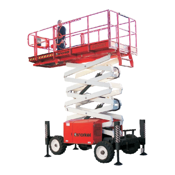
- Page 1 Die sel Gas o line Bi-En ergy 24V DC OPERATION MANUAL Se rial Num bers: Part Num ber 13865-1 S2770RT-07-000064, S3370RT-07-000061, March 2014 (Rev A) S3970RT-07-000029 and after Ver sion IV...
-
Page 2: Electrical Hazard
Electrical Hazard n Electrical Hazard Warning DANGER S3970RT, S3370RT & S2770RT ELEVATING WORK PLATFORMS ARE NOT ELECTRICALLY INSULATED. If the plat form, scis sors arm as sem bly, or any other con duc tive part of the machine con tacts a high-voltage elec tri cal con duc tor, the re sult can be SERIOUS INJURY or DEATH for per sons on or near the ma chine. -
Page 3: Introduction
Introduction n Operation Manual The most im por tant chap ter in this man ual is the safety chap ter - Chap ter 1. Take time, now, to study This man ual pro vides in for ma tion for safe and it closely. -
Page 4: Operation
Introduction This Op er a tors Man ual pro vides a daily in spec tion IMPORTANT pro ce dure that will help you keep your S3970RT / S3370RT / S2770RT in good op er at ing con di tion. Denotes important information pertaining to settings, capacities, conditions, which Do not per form other main te nance un less you are a could, if ignored lead to machine damage or... -
Page 5: Additional Information
No modification should be made to the equipment without prior written consent of the Snorkel Engineering Department. Make a pre-start inspection of the S3970RT / S3370RT / S2770RT at the beginning of each shift. A malfunctioning machine must not be used. -
Page 7: Table Of Contents
Table of Contents Electrical Hazard RCD/ELCB AC Outlet (option) ... . 2-4 Flashing Light ......2-5 Electrical Hazard Warning . - Page 8 Table of Contents Rough Terrain Scissor Interlock Tests ..7-2 Stabilisers ......8-5 Sta bi liser locked out when plat form Operating The Stabilisers Manually .
- Page 9 Table of Contents Hazardous Components ....12-1 Antifreeze (UN 1993) ....12-1 Battery, Lead/Acid (UN 2794) .
-
Page 11: Safety
1. Safety n Safe Operation Side slopes. Bumps and floor obstructions. Knowl edge of the in for ma tion in this man ual, and proper train ing, pro vide a ba sis for safely op er at ing Debris. the S3970RT / S3370RT / S2770RT. Know the lo - Overhead obstructions and electrical ca tion of all the con trols and how they op er ate to conductors. -
Page 12: Operation
Snorkel. con di tion re lat ing to ca pac ity, in tended use, or safe... -
Page 13: General Safety Precautions
1. Safety No per son shall ac cess or egress from the plat form immediately. In case of injury by escaping in the el e vated po si tion (ex cept in an emer gency) hydraulic fluid, seek medical attention at un less the re quire ments of AS2550.10 have been once. -
Page 14: Batteries
S2770RT away from the area of the spill and avoid part. See your Snorkel dealer for new decals cre at ing any source of ig ni tion un til the spilled fuel and placards. - Page 15 1. Safety LEFT HAND SIDE OF THE MACHINE 501453-000 All 4 Stabilisers On Fuel Tank Inside Cabinet & Outside Of Cabinet Door TORQUE Lug Bolts/Nuts · 90-100 Ft. Lbs.122-135 N m Check Every 30 Days 0372061 S3970RT, S3370RT & S2770RT – 13865-1 Rev A page 1 - 5...
- Page 16 1. Safety RIGHT-HAND SIDE OF MACHINE DANGER EMERGENCY OPERATION SHEARING HAZARD/CRUSHING HAZARD 1. EMERGENCY LOWERING Free-wheel the Drive Motors Death or serious injury might result from Open the free-wheeling valve [A] by turning counterclockwise until the In the event of total power failure pull the emergency lowering handle having body parts sheared or crushed as the knob stops.
- Page 17 1. Safety FRONT END OF THE MACHINE DEATH OR SERIOUS INJURY CAN RESULT FROM TIPPING OVER. TO KEEP FROM TIPPING THIS MACHINE OVER FOLLOW THESE RULES. DO NOT RAISE OR DRIVE AN ELEVATED DO NOT RAISE OR DRIVE AN ELEVATED PLATFORM ON A PLATFORM ON SLOPE...
- Page 18 1. Safety REAR END OF THE MACHINE 510 lb 260 lb 770 lb 510 lb 260 lb 770 lb (230 kg) (120 kg) (350 kg) (230 kg) (120 kg) (350 kg) 90 lb 90 lb (400 N) Max (400 N) Max 175 lb 175 lb 350 lb...
-
Page 19: Safety Devices
2. Safety Devices n Safety Device Information At ground control box For emer gency op er a tion con trols and pro ce dures see the Emer gency Op er a tion chap ter 9, in this manual. The de vices listed in this chap ter are safety de - vices. -
Page 20: High Temperature
2. Safety Devices Charging the engine will automatically shutdown Note: after 20 seconds. The ma chine should not be op er ated con tin u ously with the over load alarm sound ing. High temperature The high-tem per a ture alarm warns you that the If 110% of rated ca pac ity is reached in the en gine is over heat ing. -
Page 21: Safety Prop
2. Safety Devices The hand rails, in clud ing mid-rail and toe-board n Safety Control com bined with the gate, form a Fall Re straint Sys - tem. The Sys tem pre vents the op er a tor from reach - ing the Fall Haz ard. -
Page 22: Stabilisers (Option)
2. Safety Devices MAIN POWER......ON Enable switch EMERGENCY STOP....ON (up) The en able switch must be op er ated in con junc tion SELECTOR......PLATFORM with the plat form mov ing func tion you se lect. The pur pose of this switch is to pre vent the plat form n Stabilisers (Option) from mov ing if some thing or some one ac ci den tally pushes one of the plat form mov ing con trols. -
Page 23: Flashing Light
2. Safety Devices n Flashing Light The flash ing light alerts peo ple that the S3970RT / S3370RT / S2770RT is pres ent and that the S3970RT / S3370RT / S2770RT is mov ing. The light flashes at about one (1) flash per sec ond any time the S3970RT / S3370RT / S2770RT en gine is run ning. -
Page 25: Specifications
3. Specifications n Specifications The S3970RT / S3370RT / S2770RT se ries ma chines are scis sor-sup ported el e vat ing work plat forms built to con form to the fol low ing stan dards. OSHA Para graph 1910.67 Ti tle 29, C.F.R., Ve hi cle-Mounted El e vat ing and Ro tat ing Work Plat forms - La - bour.OSHA Para graph 1926.556 Ti tle 29, C.F.R., Ae rial Lifts - Con struc tion.Aus tra lian Stan dard AS1418-10(Int) 2004 El e vat ing Work Platforms. -
Page 26: General Specifications, Standard Machine
3. Specifications n General Specifications, Standard Machine S3370RT SPECIFICATIONS S3370RT Nominal working height 12.12m 39' 2” Roll out deck size 1200mm 48” Drive speed (below 2.4m) 0 to 4.5kph 0 to 2.8mph Drive speed (above 2.4m) 0 to 0.35kph 0 to 0.22mph Safe working load - Main deck 450kg 990lbs... -
Page 27: General Specifications, Standard Machine
3. Specifications n General Specifications, Standard Machine S2770RT SPECIFICATIONS S2770RT Nominal working height 10.28m 33' 9” Roll out deck size 1200mm 48” Drive speed (below 2.4m) 0 to 4.5kph 0 to 2.8mph Drive speed (above 2.4m) 0 to 0.9kph 0 to 0.6mph Safe working load - Main deck 580kg 1280lbs... -
Page 28: Engine Data
3. Specifications n Engine Data Engine Make Kubota Model DF752 (Option) D902 Fuel gasoline Diesel Fuel grade Unleaded ASTM Grade 2-D S5000 85 octane Gas Processors Tier 4 Compliance: (motor method Association Low Sulpher Do not use Standard 2140 ASTM Grade 2-D S500 gasoline blended Category: special with methyl... -
Page 29: Machine Component Identification
3. Specifications n Machine Component Identification 1. Base control panel 2. Serial number plate 3. Engine & fuel compartments 1. Extendable platform 2. Entry gate 3. Hydraulic compartment 4. Front end 5. Rear end 6. Guard rails 7. Steering (front) wheels 8. -
Page 31: Gauges
4. Gauges n EzCal LCD Display n Engine Oil En gine oil level is mea sured with a dip stick. Oil ca - pac i ties given in the Spec i fi ca tions chap ter 3 are ap prox i mate. True val ues will vary from ma chine to ma chine due to slight vari a tions or mod i fi ca tions during production. -
Page 32: Bubble Level
4. Gauges Bubble Level Figure 4.7 - Bubble Level A bub ble level is lo cated on the plat form side rail, be low the plat form con trol box. Watch the bub ble level while you set the sta bi lis ers man u ally. Lower the sta bi lis ers, one at a time, just enough to set the bub ble be tween the guide lines in both the fore and aft and lat eral gauges. -
Page 33: Automatic Shut-Offs And Circuit Breakers
5. Automatic Shut-offs and Circuit Breakers n Automatic Shut-offs engine shuts off. The engine will restart with low pressure but it will only run a few seconds before it automatically shuts off again. Level sensor When the level sen sor alarm sounds, au to matic in - Platform height vs. -
Page 34: Stabilisers
5. Automatic Shut-offs and Circuit Breakers The RCD (Re sid ual Cur rent De vice) is lo cated at Stabilisers the ground and will pro tect against short cir cuits to The S3970RT / S3370RT / S2770RT can not be earth. -
Page 35: Controls
6. Controls n Controls n Hydraulic Compartment This chap ter ex plains what each con trol does. This chap ter does not ex plain how to use the con - trols to pro duce use ful work, re fer to the Op er a tion chap ter 8 for that, af ter you have read this chapter. -
Page 36: Platform Control Box
6. Controls 2. Ground/Platform Key Switch: Three position switch that selects between Ground, Off, and Platform. The key is removable in the Off position only and is used to secure the machine from unauthorised use. 3. Choke: (Option gasoline engines only): Hold the choke switch down anytime you start a gasoline engine that is at ambient air temperature (a cold engine). - Page 37 6. Controls 1. Emergency Stop: Press the red button in at NOTE any time, under any conditions, and the entire machine stops - the engine turns off The wheels do not return to straight ahead, after and nothing moves. This switch must be out a turn, the way automobile wheels do.
-
Page 38: Daily Inspection And Maintenance
7. Daily Inspection and Maintenance At the start of each work day (or 8 hour shift), the Mas ter Key Switch set to OFF be fore you be gin this ma chine qual i fied op er a tor must per form the Daily in spec tion. -
Page 39: Rough Terrain Scissor Interlock Tests
7. Daily Inspection and Maintenance n Rough Terrain Scissor Interlock Tests 8. Raise the plat form above the el e va tion point, (approx. 1.5 metres, de pend ing on model). All Snor kel scis sor lifts in the Snor kel ‘SRT, SR and 9. -
Page 40: Fuel Level
7. Daily Inspection and Maintenance n Fuel Level Figure 7.5 - Fuel Leaks in Hoses & Joints Vi su ally in spect the en tire length of the fuel line, Figure 7.1 - Fuel Level from the en gine to the fuel tank, for leaks. Re move the fuel tank cap. -
Page 41: Engine Coolant
7. Daily Inspection and Maintenance n Engine Coolant n Swinging Gate Figure 7.7 - Engine Coolant Level Figure 7.9 - Swinging Gate The Kubota en gine is liq uid cooled. The cool ant In spect the gate to see that it swings freely, latches should be be tween the FULL level and the LOW se curely, and is not de formed in any way. -
Page 42: Battery Terminals
7. Daily Inspection and Maintenance n Battery Terminals Hydraulic tank cap Check to see that the cap is in place and is tight (see Fig ure 7.13). Hydraulic oil level To check the hy drau lic oil level: Com pletely lower the plat form. The hy drau lic oil level should be at the full level ac cord ing to the gauge €... -
Page 43: Tires And Wheels
7. Daily Inspection and Maintenance Pay par tic u lar at ten tion to the cyl in ders, check to see that there is no oil leak ing from the seal, also check all hoses that run to the cyl in ders. Have a qual i fied trained main te nance per son re - TORQUE pair all hy drau lic fluid leaks be fore you op er ate the... -
Page 44: Primary Fall Restraint System
7. Daily Inspection and Maintenance Vi su ally check to see that the bub ble level is not dam aged, that it is full of fluid, and the sur face on which the bub ble level is mounted is not de formed or bent out of level. -
Page 45: Flashing Light
7. Daily Inspection and Maintenance Check the Plat form Lift/Lower switch (see Fig - Check all of the lift , drive €, steer , and sta bi - liser ‚ func tions from the plat form con trol box to ure 7.26) to see that it is func tion ing prop erly by hold ing the switch up to rise plat form and push ing see that they cause the S3970RT / S3370RT /... -
Page 46: Rcd / Elcb (Option)
7. Daily Inspection and Maintenance n RCD / ELCB (Option) n Fall Restraint Lanyard Anchor Points (Option) Check all four (4) of the Fall Re straint an chor ages o n t h e f l o o r o f t h e p l a t f o r m f o r t h e S3970RT/S3370RT, and all six (6) of the Fall Re - straint an chor ages on the floor of the plat form for the S2770RT to see that they are pres ent, not de -... -
Page 47: Operator Manual
7. Daily Inspection and Maintenance n Operator Manual Figure 7.34 - Operator Manual Holder Check that the op er a tion man ual is in the holder. page 7 - 10 Rev A S3970RT, S3370RT & S2770RT – 13865-1... - Page 48 7. Daily Inspection and Maintenance S3970RT, S3370RT & S2770RT – 13865-1 Rev A page 7 - 11...
-
Page 49: Placards And Decals
451986 501453-000 Decal - Foot crush hazard Decal - Explosive fumes 476706 Decal - Danger with alarm 12574 511101-000 Decal - Snorkel logo Decal - Lower control box 560240 Decal - Upper control box 12689 Decal - Emergency stop upper... -
Page 50: Inspection Drawing
7. Daily Inspection and Maintenance Inspection drawing RIGHT HAND SIDE 33 X All 4 Stabilisers LEFT HAND SIDE REAR END FRONT END S3970RT, S3370RT & S2770RT – 13865-1 Rev A page 7 - 13... -
Page 52: Operation
8. Operation n Operating Procedures This chap ter ex plains how to start and run the ma - chine. Read and un der stand all the pre vi ous chap - ters be fore you be gin to operate the ma chine n Control Stations the ma chine can be started and op er ated from the ground con trol box or from the plat form con trol box. -
Page 53: Operating From The Ground Control
8. Operation Be gin at the sec tion en ti tled Op er at ing From The If the engine does not start in 20 seconds, release the start switch ƒ then wait 60 Plat form Con trol Box if you in tend to start and run the S3970RT / S3370RT / S2770RT from the plat - seconds before trying to start the engine again with the Glow-Plug switch ‚... - Page 54 8. Operation 7. Press the Glow Plug switch ƒ down and hold, for no lon ger than 20 sec onds, then re lease it just be fore start ing the en gine for an en gine that is at am bi ent air tem per a ture (a cold engine).
-
Page 55: Driving
8. Operation n Driving 6. To make a right or left turn, press and hold the Steering rocker-switch „ on top of the 1. The engine should be running. If not, start it Joystick Controller (see Figure 8.9). from the platform control box as described previously. -
Page 56: Raising The Platform
8. Operation n Stabilisers Raising the Platform To raise the plat form from the plat form con trol box § If your ma chine is not fit ted with do the fol low ing: sta bi lis ers you do not need to read 1. -
Page 57: Operating The Stabilisers Manually
8. Operation n Operating The Stabilisers Manually To set the stabilisers 1. The engine must be running and the S3970RT / S3370RT / S2770RT set for platform control box operation. Note: In order to operate any of the stabilisers you must squeeze the joystick trigger w at the same Figure 8.13 time as you operate the individual stabiliser... -
Page 58: Operating The Auto Level System
8. Operation 2. Push and hold the Stabiliser switches … NOTE: forward until all the stabilisers are completely up (see Figure 8.15). Manual or auto levelling is possible any time that stabiliser movement is allowed. For example, the n Operating The Auto Level System machine can be manually levelled part way and then auto levelled without the necessity of retracting the stabilisers between the two (2) -
Page 59: Extending The Multi-Position Platform
8. Operation n Extending The Multi-Position Platform DECK EXTENSION HANDLE LOCKED DECK EXTENSION HANDLE UNLOCKED Figure 8.18 NON-EXTENDABLE EXTENDABLE The po si tion ing of out rig ger footplates on ramps PLATFORM PLATFORM and slopes cre ates the risk of the ma chine slid ing down the ramp or slope (see Fig ure 8.19 &... -
Page 60: Emergency Operation
9. Emergency Operation n Emergency Operation Procedures Push ei ther Emer gency Stop switch, (see Fig ures 9.1 and 9.2) at any time, and the en tire ma chine The fol low ing pro ce dures are emer gency pro ce - stops, the en gine turns off, and noth ing moves. -
Page 61: Pushing / Towing
9. Emergency Operation 3. Squeeze the Safety Control and push the Joystick Controller ‚ (see Figure 9.3) forward. The platform should lower. If it does not lower, call for help from someone on the ground. The per son on the ground should do the fol low ing: Figure 9.6 - Manual Bleed Down Control 6. - Page 62 9. Emergency Operation 2. At the ground control box set the CAUTION EMERGENCY STOP switch € to off, turn the MAIN POWER switch off and remove The S3970RT / S3370RT / S2770RT drive the key (see Figure 9.8). motors will be ruined if the S3970RT / S3370RT / S2770RT is pushed (or pulled) faster than 2 mph (3.2 km/hr).
-
Page 64: Stowing And Transporting
10. Stowing and Transporting n Stowing To lock the ma chine: At the end of each work day (or in prep a ra tion for trans port ing, push ing, lift ing, or stor age) a qual i fied op er a tor should put the S3970RT / S3370RT / S2770RT into its stowed po si tion then lock it. -
Page 65: Securing To A Transport Vehicle
10. Stowing and Transporting 1. Visually inspect the alignment of the loading Securing to a Transport Vehicle ramp and the truck or trailer. They should This pro ce dure as sumes that you have just fin - both be on the same straight line. ished the pre vi ous sec tion and that the wheels are 2. -
Page 66: Towing
10. Stowing and Transporting Snorkel New Zealand Engineering Department Figure 10.9 - Tie-down Lugs Chocks may be re moved at this time, though it is a good idea to leave them in place. Re verse the above pro ce dure af ter trans port ing. - Page 67 10. Stowing and Transporting When re turn ing a ma chine to ser vice from a sus tained pe riod of dis use (over 90 days) per form the 90 day in spec tion. Also re place the en gine oil and hy drau lic oil and all fil ters.
-
Page 68: Options
11. Options This chap ter lists and ex plains the op tions avail - Af ter se lect ing the DC mode, turn the se lec tor able for the ma chine. switch to the plat form po si tion (see Fig ure 11.3) n Bi-En ergy Option This con sists of a com bi na tion of both a die sel en - gine and a 24V DC mo tor to give a Bi-En ergy op -... -
Page 69: Battery Charger
11. Options bat ter ies on-board charger to en sure proper op er a tion. The bat ter ies are en closed in a cab i net mounted at the front of the ma chine. Unscrew the knurled knobs at each end of the cab i - net to re move the lid to gain ac cess to the bat ter ies (see Fig ure 11.5). -
Page 70: Batteries - General Maintenance
11. Options If the only fuel source you see is one (1) or Batteries - General maintenance more LP tanks, the S3970RT / S3370RT / Al ways keep the bat ter ies clean, free of dirt and S2770RT has a special gasoline engine cor ro sion. -
Page 71: Operating From The Ground Control
11. Options Set the Battery switch (see Figure 11.12) to on. Figure 11.13 2. Set the Emergency Stop switch € to on Figure 11.11 - LPG Fuel Tank Replacement (out). To re place an LPG tank: Close the valve (see 3. -
Page 72: Operating From The Platform Control Box
11. Options Figure 11.16 1. Set the Battery switch to on (see Figure Figure 11.15 11.16). 5. For a dual-fuel en gine: Set the Fuel switch (not shown here) to LP fuel or gas o line fuel de pend ing on which you want to use. -
Page 73: Rcd / Elcb Outlet
11. Options 4. For LP operation: Completely open the valve ‚ (see Figure 11.18) on top of the LP tank (unscrew n RCD / ELCB Outlet counterclockwise until it stops). 5. For a dual-fuel engine: On the Lower Control Box: Set the FUEL switch (not shown here) to gasoline or LP gas depending on which you want to use. -
Page 74: Electrical Outlet
11. Options NOTE These anchors are not for lifting or tying down the machine. You should at tach your fall pro tec tion to the an - chors if work rules re quire it. n Electrical Outlet Power Outlet At Platform Figure 11.22 - Electrical Outlet The elec tri cal out let on the plat form, and its power ca ble, are de signed to sup ply 2 kW of con tin u ous... -
Page 76: Fire Fighting And Chemical Containment
12. Fire Fighting and Chemical Containment n Hazardous Components Special fire fighting procedures: The S3970RT / S3370RT / S2770RT may con tain Use pos i tive pres sure, self con tained breath ing ap - some or all the fol low ing ma te ri als and ob jects that pa ra tus. -
Page 77: Foam In Tires
12. Fire Fighting and Chemical Containment Burning produces intense heat, dense Special fire fighting procedures: smoke, and toxic gases, such as carbon Use wa ter to keep fire ex posed con tain ers cool. If monoxide, oxides of nitrogen, and traces of leak or spill has not ig nited, use wa ter spray to dis - hydrogen cyanide. -
Page 78: Hydraulic Oil (Un 1270)
12. Fire Fighting and Chemical Containment c o m p l y i n g w i t h f e d e r a l , s t a t e , a n d l o c a l NOTE regulations. - Page 79 12. Fire Fighting and Chemical Containment Special fire fighting procedures: Wa ter or foam may cause froth ing. Use wa ter to keep fire ex posed con tain ers cool. Wa ter spray may be used to flush spills away from ex po sures. Unusual fire and explosion hazards: Prod ucts of com bus tion may con tain car bon mon - ox ide, car bon di ox ide, and other toxic ma te ri als.
-
Page 80: Operator's Troubleshooting
13. Operator's Troubleshooting n Troubleshooting The sec ond col umn lists some of the causes for each prob lem. The third col umn lists rem e dies. All of the ac tions de scribed in this chap ter may be per formed by the ma chine op er a tor, a trained and CAUTION qual i fied ser vice tech ni cian is not required. - Page 81 13. Operator's Troubleshooting Problem Cause Remedy Platform will not go up Engine is not running. Start the engine from the control station or down. where you will operate the S3970RT / S3370RT / S2770RT. Switches set wrong For ground control operation: (Lift Indicator light is lit).
-
Page 82: Appendix A. Glossary
Appendix A. Glossary „ aerial platform A - Anchorage - a fixed structure to which the components of the system are rigged. a mobile device that has an adjustable position B - Body Wear - a full body har ness worn by platform, supported from ground level by a the per son (re ferred to as a "safety har ness"... - Page 83 „ the raidus of the circle created by the wheel during a 360O turn with the steering wheels turned to maximum. inside turning radius is the © Snorkel – all rights reserved Printed in New Zealand...
- Page 84 Index Bleed down, 9-1 Emergency stop, 9-1 Additional information Pushing, 9-2 Introduction - page iv, A-iv Engine Automatic Shut-offs, 5-1 Coolant, 3-4 Alternator Not Charging, 5-1 Fuel, 3-4 Dynamic Brakes, 5-1 Fuel grade, 3-4 Engine Oil Pressure, 5-1 Make, 3-4 Engine Temperature, 5-1 Model, 3-4 Level Sensor, 5-1...
- Page 85 Index Safety Alerts, Caution, Danger, Warning, Nominal working height, 3-1, 3-2, 3-3 Important see Introduction - page iii Safety Devices Operating Procedures, 8-1 Alarms, 2-1 Control Stations, 8-1 Drive (reverse), 2-2 Operating From Ground Controls High temperature, 2-2 Starting a gasoline, LP, or duel fuel engine, Level sensor, 2-2 11-4 Low oil pressure, 2-2...
- Page 86 Local Distributor / Lokaler Vertiebshandler / Distributeur local El Distribuidor local / Il Distributore locale EUROPE, MIDDLE EAST AFRICA & ASIA PHONE: +44 (0) 845 1550 O57 FAX: +44 (0) 845 1557 756 NORTH & SOUTH AMERICA PHONE: +1 785 989 3000 TOLL FREE: +1 800 255 0317 FAX: +1 785 989 3070 AUSTRALIA...
Need help?
Do you have a question about the S3970BE and is the answer not in the manual?
Questions and answers