
Related Manuals for Snorkel S2646E


Summary of Contents for Snorkel S2646E
- Page 1 OPERATOR’S MANUAL Part Number 0410051 February 2011 Serial number 1107120411 and after...
- Page 2 Proposition 65 Warning Battery posts, terminals and related accessories contain lead and lead components, chemicals known to the State of California to cause cancer and birth defects or other reproductive harm. Wash hands after handling. © Snorkel – all rights reserved...
-
Page 3: Table Of Contents
Chapter 6 – Batteries Chapter 2 – Specifications General Maintenance ........... 17 Component Identification ......... 3 Charging ............. 17 General Specifications S2646E ....... 4 Aerial Platform ............ 4 Chapter 7 – Controls Platform ............. 4 Battery Disconnect Switch........19 Function Speed ........... 4 Lower Controls ............. - Page 4 Drive/Lift Level Sensor Interlock ......34 Steering .............. 35 Platform .............. 35 Raising and Lowering ........35 Extending ............35 Swing-Down Rails ..........36 Swing-Out Trays ..........36 Electrical Power Outlet ......... 37 Wallboard Loading ..........37 S2646E/S3246E – 0410051...
-
Page 5: Chapter 1 - Introduction
The S2646E has one hy- draulic cylinder to raise and lower the platform and the All information in this manual is based on the latest prod- S3246E has two cylinders. -
Page 6: Maintenance
Owners, Users, Operators, Lessors and Lessees of law. ANSI/SIA A92.6-1999 Self-Propelled Elevating Work Plat- forms” is available from Snorkel dealers or from the fac- Maintenance tory upon request. Every person who maintains, inspects, tests, or repairs the aerial platform must be qualified to do so. -
Page 7: Chapter 2 - Specifications
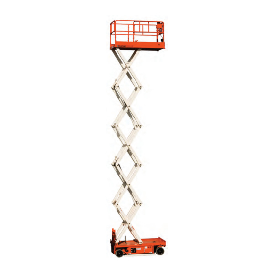
Front Right Side Electrical Operator’s Power Outlet Upper Controls Guardrails Manual Lifting Lugs Scissors Structure Emergency Forklift Lowering Pockets Handle Chassis Drive and Steer Wheels Battery Disconnect Tie-down Lugs Battery Charger Switch Battery Tray Rear Left Side S2646E/S3246E – 0410051... -
Page 8: General Specifications S2646E
Chapter 2 – Specifications General Specifications S2646E Aerial Platform Function Speed Working height 32′ (9.75 m) Platform raise 25 to 35 seconds Platform lower 50 to 60 seconds Maximum platform height 26′ (7.9 m) Turning radius High drive Inside 10″ (25.4 cm) Platform lower than 7 to 8 feet (2.1 to 2.4 m) -
Page 9: General Specifications S3246E
9.25 US gal (35 l) Maximum operating temperature 160°F (71°C) Hydraulic fluid recommended Above 10°F (-13°C) Mobil DTE-13M (ISO VG32) Below 10°F (-13°C) Mobil DTE-11M (ISO VG15) Ambient Air Temperature Operating Range Fahrenheit 0°F to 110°F Celsius -18°C to 43°C S2646E/S3246E – 0410051... - Page 10 Chapter 2 – Specifications S2646E/S3246E – 0410051...
-
Page 11: Chapter 3 - Safety
Over 50kV to 200kV 4.60 Over 200kV to 350kV 6.10 Over 350kV to 500kV 7.62 10.67 Over 500kV to 750kV Over 750kV to 1000kV 13.72 Table 1 – Minimum Safe Approach Distance Figure 4 – Minimum Safe Approach Distance S2646E/S3246E – 0410051... -
Page 12: Prestart Inspection
28 mph (12.5 m/s). ing the chassis or platform. Allow sufficient room and time to stop movement to avoid contact with Do not operate the aerial platform within 4′ (1.2 m) of any structures or other hazards. drop-off or hole. S2646E/S3246E – 0410051... -
Page 13: Electrical System
Death or serious injury could that extend beyond the platform guardrails without prior result from a chemical explosion. Do not smoke or written consent from Snorkel. permit open flames or sparks when checking the batteries. Do not operate the aerial platform from trucks, trailers, railway cars, floating vessels, scaffolds, or similar equip- Battery acid can damage the skin and eyes. - Page 14 Chapter 3 – Safety S2646E/S3246E – 0410051...
-
Page 15: Chapter 4 - Safety Devices
The aerial platform can tip over if it becomes un- stable. Death or serious injury will result from a tip- over accident. Do not drive or position the aerial platform for elevated use within four feet of any drop-off, hole, or other tip-over hazard. S2646E/S3246E – 0410051... -
Page 16: Drive/Lift Pothole Protector Interlock
Stand clear while rais- ing and lowering the platform. Figure 4.5 – Safety Prop Be careful when lowering the platform. Keep hands and fingers away from the scissors structures components. S2646E/S3246E – 0410051... -
Page 17: Guardrails
(GFCI) to provide protection for personnel. The light flashes at about one flash per second when the machine is set up for operation from the upper controls. Figure 4.7 – Electrical Power Outlet S2646E/S3246E – 0410051... - Page 18 Chapter 4 – Safety Devices S2646E/S3246E – 0410051...
-
Page 19: Chapter 5 - Gauges And Displays
The ammeter is located on the battery charger (refer to Figure 5.2). When the batteries are charging, the amme- ter displays the level of current flow from the charger to the batteries. Ammeter Figure 5.2 – Battery Charger S2646E/S3246E – 0410051... - Page 20 Chapter 5 – Gauges and Displays S2646E/S3246E – 0410051...
-
Page 21: Chapter 6 - Batteries
Do not leave the battery charger on for more than two days. 6. Check the battery water level. Add water to individual cells only if the plates are exposed. Replace the bat- tery caps. S2646E/S3246E – 0410051... - Page 22 Chapter 6 – Batteries S2646E/S3246E – 0410051...
-
Page 23: Chapter 7 - Controls
• Drive range switch • Control selector switch • Joystick to control platform lift, drive and steer • Platform raise/lower switch The optional horn button and battery condition indicator gauge may also be located at the upper control station. S2646E/S3246E – 0410051... -
Page 24: Emergency Stop Button
Movement of the joystick in a given direction produces a breaker trips repeatedly. corresponding movement of the aerial platform. The steer- ing and drive functions may be operated separately or Push the reset button to reset the circuit breaker. simultaneously. S2646E/S3246E – 0410051... -
Page 25: Chapter 8 - Prestart Inspection
Death or serious injury can 3. Observe the reading on the ammeter. The reading result from a chemical explosion. Do not smoke or should be 20 amps. permit open flames or sparks when checking the batteries. S2646E/S3246E – 0410051... -
Page 26: Safety Prop
Figure 8.5 – Cables and Wiring Harness drops onto personnel working within the scissors arms or under the raised platform. Properly posi- tion the safety prop before reaching through the scissors structure. S2646E/S3246E – 0410051... -
Page 27: Hydraulic System
Refer to Chapter 2 – Specifications for the Figure 8.8 – Free-Wheeling Valve proper type and grade of hydraulic fluid to use. The need to regularly add fluid indicates a leak that should be cor- rected. S2646E/S3246E – 0410051... -
Page 28: Tires And Wheels
Clearance should be at about 4″ (10.1 cm) on both sides of the aerial platform. 1. Turn the battery disconnect switch on. 2. At the lower controls, pull the emergency stop switch outward to the on position. S2646E/S3246E – 0410051... -
Page 29: Emergency Lowering
Pay close attention to welds in areas where changes in the platform should stop raising and an alarm should cross section take place and near the attachment points sound at approximately 7 to 8 feet (2.1 to 2.4 m) of highly loaded components. S2646E/S3246E – 0410051... -
Page 30: Slide Pads
Hold the handles downward to release the pins and to extend the platform. Extend the platform while checking for proper operation. Extend the platform and inspect the weldments for defor- mation and damage. Visually check the platform welds for cracks. S2646E/S3246E – 0410051... -
Page 31: Swing-Down Rails
With the aerial platform stowed, test the operation of each the aerial platform is in motion. control from the upper control station (refer to Figure 8.20). S2646E/S3246E – 0410051... -
Page 32: Electrical Power Outlet
Placard and decal kits are available from Snorkel. The safety related placards and decals are illustrated on the following pages. S2646E/S3246E – 0410051... - Page 33 B E F O R E O P E R A T I N G T H I S M A C H I N E . 0372000 0372000 Rear 0074311 Rod end of lift cylinder(s) 451986 Top of Chassis 0074311 S2646E/S3246E – 0410051...
- Page 34 Do not remove any weight from this machine. Any weight added must be distributed equally on each axle. Axle weights with machine in the stowed position. Left Side STEER AXLE DRIVE AXLE 0070901 0070901 300760 451986 300700 0361259 Front 300700 S2646E/S3246E – 0410051...
-
Page 35: Prestart Inspection Checklist
Shuts off upper controls Lowering alarm Sounds when platform lowers Drive motion alarm Sounds when aerial platform moves Electrical power outlet Proper operation Battery condition indicator Proper operation Horn Sounds when activated Placards and Decals In place and readable S2646E/S3246E – 0410051... - Page 36 Chapter 8 – Prestart Inspection S2646E/S3246E – 0410051...
-
Page 37: Chapter 9 - Operation
1. Perform a prestart inspection (refer to as Chapter 8). The upper controls will not operate while the control se- lector is in the lower position. 2. Close and latch the battery and hydraulic trays. 3. Place the battery disconnect switch in the on posi- tion. S2646E/S3246E – 0410051... -
Page 38: Driving
1. Place the drive/lift selector switch (refer to Figure 9.2) When the platform is elevated above 7 to 8 feet (2.1 to in the drive position. 2.4 m), lift and drive functions are interlocked through a level sensor system. If the chassis is tilted more than S2646E/S3246E – 0410051... -
Page 39: Steering
• To raise the platform, slowly pull the joystick back until the desired speed is reached. • To lower the platform, slowly push the joystick forward. S2646E/S3246E – 0410051... -
Page 40: Swing-Down Rails
Batteries and hydraulic components are enclosed in controls on the floor of the platform. swing-out trays (refer to Figure 9.7) on each side of the chassis. Tray Latch Figure 9.5 – Upper Controls Figure 9.7 – Swing-Out Tray S2646E/S3246E – 0410051... -
Page 41: Electrical Power Outlet
(refer to Figure 9.9). Power-Input Connector Figure 9.9 – Rear of Chassis To use the outlet, plug a source of power into the power- input connector. Unplug the source of power before mov- ing the aerial platform. S2646E/S3246E – 0410051... - Page 42 Chapter 9 – Operation S2646E/S3246E – 0410051...
-
Page 43: Chapter 10 - Stowing And Transporting
Use the following procedure to winch the aerial platform 3. If lifting from the rear of the machine, insert the forklift onto the transport vehicle. forks into the pockets (refer to Figure 10.1). S2646E/S3246E – 0410051... -
Page 44: Driving
The aerial platform can tip over if it becomes un- stable. Death or serious injury will result from a tip- over accident. Do not drive on ramps that exceed 25 percent grade, or where conditions of the ramp could cause driving to be hazardous. S2646E/S3246E – 0410051... -
Page 45: Hoisting
When using cables, use form. rigid corner protectors at any point where the cable contacts on sharp corners to prevent damaging the S2646E/S3246E – 0410051... -
Page 46: Securing For Transport
7. Use chains or straps to securely fasten the aerial platform to the transport vehicle using the front and rear tie-down lugs as attachment points. Proper tie- down and hauling is the responsibility of the carrier. S2646E/S3246E – 0410051... -
Page 47: Chapter 11 - Emergency Operation
Death or serious injury could result. aerial platform. Re-enable the brakes before operating the aerial platform. 6. Close the free-wheeling valve after moving the aerial platform. 1. Chock the wheels to prevent uncontrolled motion of the aerial platform. S2646E/S3246E – 0410051... - Page 48 Chapter 11 – Emergency Operation 7. Drive the aerial platform forward or backward and then stop, to reset the parking brakes. 8. Verify that the drive system and brakes operate properly before operating the aerial platform. S2646E/S3246E – 0410051...
-
Page 49: Chapter 12 - Troubleshooting
Drive/lift selector is in the lift position. Lower the platform and drive to a level Machine is not on a level surface or surface. too steep a grade. Fully close the free-wheeling valve. Free-wheeling valve is open. S2646E/S3246E – 0410051... - Page 50 Ammeter does not indicate a read- No source of power. Make sure power source is plugged ing when charging the batteries. in and turned on. Charger power fuse is blown. Stow the machine and do not oper- ate until repairs are made. S2646E/S3246E – 0410051...
- Page 51 Hydraulic system component failure. Stow the machine and do not oper- ate until repairs are made. Failure of hose, tube, fitting, seal, etc. Stow the machine and do not oper- Severe hydraulic leak. ate until repairs are made. S2646E/S3246E – 0410051...
- Page 52 S2646E/S3246E – 0410051...
-
Page 53: Appendix A - Glossary
Although federal building beam, girders or columns. An aerial platform is not a fall regulations, OSHA, ANSI, and Snorkel do not require the use of arrest anchorage. additional fall protection beyond the platform guardrails on scissor lift aerial platforms, local, state, or employer rules may require their platform –... - Page 54 Appendix A – Glossary upper controls – the controls located on or beside the platform used for operating some or all of the functions of the aerial platform. wheelbase – the distance from the center of the rear wheel to the center of the front wheel.
-
Page 55: Limited Warranty
LIMITED WARRANTY Snorkel warrants each new machine manufactured and sold by it to be free from defects in material and workmanship for a period of one (1) year from date of delivery to a Customer or for one year after the machine has been placed in first service in a Dealer rental fleet, whichever comes first. - Page 56 Local Distributor / Lokaler Vertiebshändler / Distributeur local El Distribuidor local / ll Distributore locale EUROPE, MIDDLE EAST AFRICA & ASIA PHONE: +44 (0) 845 1550 057 FAX: +44 (0) 845 1557 756 NORTH & SOUTH AMERICA PHONE: +1 785 989 3000 TOLL FREE: +1 800 255 0317 FAX: +1 785 989 3070 AUSTRALIA...
Need help?
Do you have a question about the S2646E and is the answer not in the manual?
Questions and answers