Table of Contents
Advertisement
Advertisement
Table of Contents

Subscribe to Our Youtube Channel
Related Manuals for Unitronics Unistream URD-0800


Summary of Contents for Unitronics Unistream URD-0800
- Page 1 UniStream Remote I/O User Manual Revision 2.10 April, 2019 Unitronics...
-
Page 2: Table Of Contents
IP Address Setup using BOOTP Server ..........................17 Editing the IP defaults................................17 Selecting the IP Configuration Method ..........................17 Configuring IP using Unitronics BOOTP Server........................18 LED Indicators .................................... 21 MOD (Module Status LED)..............................21 LINK (Physical Connection LED) ............................22 ACTIVE (Exchange Data/Traffic Present LED) ........................ - Page 3 URD-0032NG-4 (DO32N4) - 32 Digital Outputs, (Sink) ......................65 Wiring Diagram ................................. 66 LED Indicators .................................. 67 URD-0004RH (DO04RH) - 4 Relay Outputs ..........................68 Wiring Diagram ................................. 69 LED Indicators .................................. 70 URD-0004SK (DO04SK) - 4 Solid State Relay ..........................71 Unitronics...
- Page 4 LED Indicators ................................109 URA-0004W (AO04W) - 4 Analog Current Outputs 12bit ......................110 Wiring Diagram ................................111 LED Indicators ................................112 URA-0008W (AO08W) - 8 Analog Current Outputs 12bit ......................113 Wiring Diagram ................................114 LED Indicators ................................115 Unitronics...
- Page 5 URP-C24V24V (PC2424) - 8 24VDC Potential Distribution ...................... 152 Wiring Diagram ................................153 LED Indicators ................................154 URP-C0V24V (PC024) - 4 24VDC, 4 0VDC Potential Distribution ................... 155 Wiring Diagram ................................156 LED Indicators ................................157 URP-PDIST (PPDIST) - External Universal Power Distribution ....................158 Unitronics...
- Page 6 Wiring Diagram ................................159 LED Indicators ................................160 URP-SHIELD (PSHLD) - External Universal Shield Distribution ....................161 Wiring Diagram ................................162 LED Indicators ................................163 I/O Module Dimensions................................164 I/O Module (10RTB) ................................164 I/O Module (18RTB) ................................164 Unitronics...
-
Page 7: About Unistream® Remote I/O
You can use both lines with the same controller at the same time. Note that the adapters and modules of each line are not interchangeable. You may only use: Uni-Local Expansion Adapters with Uni-I/O modules UniStream Remote I/O Adapters with UniStream Remote I/O modules. Unitronics... -
Page 8: Unitronics Remote I/O Models
4/19 Unitronics Remote I/O Models Adapter Ethernet Support Operating Operating Label Article Description Ports Slots Voltage temperature -40°C to 70°C (-40°F to 158°F) on 0.8A load UniStream Remote IO URB-TCP URB-TCP Up to 63 24VDC Ethernet Adapter -40°C to 60°C (-40°F to 140°F) on 1.5A load... -
Page 9: Analog Inputs 12 Bit
16 Analog Voltage Outputs, 18 RTB Analog Outputs 16 bit Label Article Description Number of IO AO04Y URA-0004Y 4 Analog Current Outputs, 10 RTB AO04Z URA-0004Z 4 Analog Voltage Outputs, 10 RTB AO16Z8 URA-0016Z-8 16 Analog Voltage Outputs, 18 RTB Unitronics... -
Page 10: Temperature
Protection IP20, NEMA1 UL temperature -20°C to 60°C (-4°F to 140°F) Storage temperature -40°C to 85°C (-40°F to 185°F) Relative Humidity (RH) 5% to 90% (non-condensing) Shock IEC 60068-2-27 Vibration IEC 60068-2-6 Mounting DIN Rail Certifications CE , UL Unitronics... -
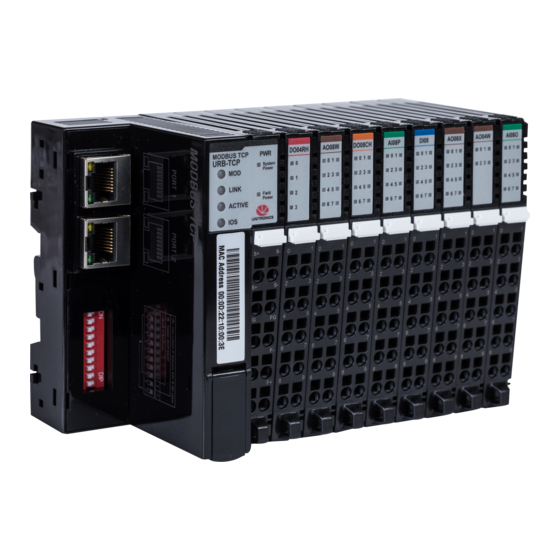
Page 11: Urb-Tcp (Urb-Tcp) - Unistream Remote Io Ethernet Adapter
All examples and diagrams are intended to aid understanding, and do not guarantee operation. Unitronics accepts no responsibility for actual use of this product based on these examples. Please dispose of this product according to local and national standards and regulations. -
Page 12: Installation - Din-Rail Module Mounting
4/19 Installation - DIN-Rail Module Mounting 1. Press down the module lightly on the DIN rail until the lower ridge click onto the rail. Unitronics... -
Page 13: How To Remove The Adapter Module From The Din-Rail
2. Pull the module off the rail. How to remove the RTB (Removable Terminal Block) from the I/O module 1. Pull out the plastic belt from the RTB. 2. Apply more force until the I/O module is pulled away from the I/O module. Unitronics... -
Page 14: How To Connect The I/O Modules
How to connect the I/O modules 1. Line up the grooves on the module with the grooves on the adapter (if it is the first module) or on the adjacent module, and slide the module into place as shown in the next image. Unitronics... -
Page 15: Specifications
Supply voltage : 24VDC typical (Max. 32VDC) Field Power Range is different depending on URI module series. Refer to URI module`s specification. Max. Current Field Power Contact DC 10A Max Weight 162g Module Size 54mm x 99mm x 70mm Unitronics... -
Page 16: Wiring Diagram
System Power, 24V System Power, Ground System Power, 24V System Power, Ground Field Power, Ground Field Power, Ground Field Power, 24V Field Power, 24V RJ45 Socket RJ-45 Signal Name Description Transmit + Transmit - Receive + Receive - Case Shield Unitronics... -
Page 17: Ip Address Setup Using Bootp Server
In case that the BOOTP/DHCP server does not respond, the Adapter applies the latest saved IP address. Raise #10 to set IP via DIP switch: You can then set the IP according to the description in the next table. Unitronics... -
Page 18: Configuring Ip Using Unitronics Bootp Server
Enable IP Address set by DIP Switches Value Configuring IP using Unitronics BOOTP Server Before you can set the IP address of the Remote IO adaptor via Unitronics BOOTP Server, you must raise DIP #9 (check that #10 is down) 1. Power OFF the URB adapter. - Page 19 7. Locate the adapter’s MAC address and double-click on the row. 8. Enter the required IP address and select your PC Network card. 9. Click Ok. Now you should see the device in the bottom window including the IP address. Unitronics...
- Page 20 11. Use Ping from command line to check that the IP address is replying. 12. If the adapter replies successfully, then power off the adapter (URB-TCP) and lower DIP switch #9 (set to OFF). 13. Configure the adapter and IO modules in UniLogic and test. Unitronics...
-
Page 21: Led Indicators
Protocol Error Green/Red Toggle Protocol error such as watchodg error, etc. Minor Fault Flashing Red Recoverable Fault. - EEPROM checksum fault. Unrecoverable Fault The device has an unrecoverable fault. - Memory error or CPU watchdog error. Unitronics... -
Page 22: Link (Physical Connection Led)
- Mismatch vendor code between adapter and expansion module. Field Power, System Power LED (Field Power, System Power Status LED) Status Indication No field, System power Not supplied 24VDC field power, 5VDC system power. Supplied field, System power Green Supplied 24VDC field power, 5VDC system power. Unitronics... -
Page 23: Urd-0800 (Di08) - 8 Digital Inputs (Sink Or Source)
Supply voltage : 24VDC nominal Voltage range : 15 to 32VDC Power dissipation : 0mA @ 24VDC I/O Cable Max. 2.0���� Wiring (AWG 14) Weight Module Size 12mm x 99mm x 70mm Operating temperature -40°C to 70°C (-40°F to 158°F) Unitronics... -
Page 24: Wiring Diagram
4/19 1. Wiring Diagram Pin No. Signal Description Pin No. Signal Description Input 0 Input 1 Input 2 Input 3 Input 4 Input 5 Input 6 Input 7 Common(Sink Oper.0V / Common(Sink Oper.0V / Source Oper.24V) Source Oper.24V) Unitronics... -
Page 25: Led Indicators
LED Function / Description LED Color Input 0 Green Input 1 Green Input 2 Green Input 3 Green Input 4 Green Input 5 Green Input 6 Green Input 7 Green Status Indication No Signal Normal Operation On Signal Green Normal Operation Unitronics... -
Page 26: Urd-1600-8 (Di168) - 16 Digital Inputs (Sink / Source)
Supply voltage : 24VDC nominal Voltage range : 15 to 32VDC Power dissipation : 0mA @ 32VDC I/O Cable Max. 0.75���� Wiring (AWG 18) Weight Module Size 12mm x 109mm x 70mm Operating temperature -40°C to 70°C (-40°F to 158°F) Unitronics... -
Page 27: Wiring Diagram
Input 1 Input 2 Input 3 Input 4 Input 5 Input 6 Input 7 Input 8 Input 9 Input 10 Input 11 Input 12 Input 13 Input 14 Input 15 Common(Sink Oper.0V / Source Oper.24V) Common(Sink Oper.0V / Source Oper.24V) Unitronics... -
Page 28: Led Indicators
Green Input 7 Green Input 8 Green Input 9 Green Input 10 Green Input 11 Green Input 12 Green Input 13 Green Input 14 Green Input 15 Green Status Indication Not Signal Normal Operation On Signal Green Normal Operation Unitronics... -
Page 29: Urd-3200-4 (Di324) - 32 Digital Inputs (Sink / Source)
Field Power Supply voltage : 24VDC nominal Voltage range : 15 to 32VDC Power dissipation : 0mA @ 24VDC Wiring Module connector : HIF3BA-40D-2.54R Weight Module Size 12mm x 109mm x 70mm Operating temperature -40°C to 70°C (-40°F to 158°F) Unitronics... -
Page 30: Wiring Diagram
Input 17 Input 18 Input 19 Input 20 Input 21 Input 22 Input 23 Input 24 Input 25 Input 26 Input 27 Input 28 Input 29 Input 30 Input 31 Common(Sink Oper.0V / Source Oper.24V) Common(Sink Oper.0V / Source Oper.24V) Unitronics... -
Page 31: Led Indicators
2. LED Indicators LED No. LED Function / Description LED Color INPUT 0 Green INPUT 1 Green INPUT 2 Green Green INPUT 31 Green Status Indication No Signal Normal Operation On Signal Green Normal Operation Unitronics... -
Page 32: Urd-0400B (Di04B) - 4 Digital Inputs
Field Power Supply voltage : 24VDC nominal Voltage range : 15 to 32VDC (AC Power Not used) Wiring I/O Cable Max. 2.0���� (AWG 14) Weight Module Size 12mm x 99mm x 70mm Operating temperature -40°C to 70°C (-40°F to 158°F) Unitronics... -
Page 33: Wiring Diagram
1. Wiring Diagram Pin No. Signal Description Pin No. Signal Description Input 0 Input 1 Input 2 Input 3 Input Common ( L2/N ) Input Common ( L2/N ) Input Common ( L2/N ) Input Common ( L2/N ) Unitronics... -
Page 34: Led Indicators
4/19 2. LED Indicators LED No. LED Function / Description LED Color Input 0 Green Input 1 Green Input 2 Green Input 3 Green Status Indication No Signal No Input Signal On Signal Green Normal Operation Unitronics... -
Page 35: Urd-0400C (Di04C) - 4 Digital Inputs
Field Power Supply voltage : 24VDC Voltage range : 15 to 32VDC (AC Power Not used) Wiring I/O Cable Max. 2.0���� (AWG 14) Weight Module Size 12mm x 99mm x 70mm Operating temperature -40°C to 60°C (-40°F to 140°F) Unitronics... -
Page 36: Wiring Diagram
1. Wiring Diagram Pin No. Signal Description Pin No. Signal Description Input 0 Input 1 Input 2 Input 3 Input Common ( L2/N ) Input Common ( L2/N ) Input Common ( L2/N ) Input Common ( L2/N ) Unitronics... -
Page 37: Led Indicators
2. LED Indicators LED No. LED Function / Description LED Color Input 0 Green Input 1 Green Input 2 Green Input 3 Green Status Indication No Signal No Input Signal On Signal Green Normal Operation Unitronics... -
Page 38: Urd-0200E (Di02E) - 2 High Speed Counters / Encoder Inputs
I/O to Field Power : Non-Isolation Supply voltage : 24Vdc nominal Field Power Voltage range : 18 to 32VDC Wiring I/O Cable Max. 2.0���� (AWG 14) Weight Module Size 12mm x 90.5mm x 65mm Operating temperature -40°C to 70°C (-40°F to 158°F) Unitronics... -
Page 39: Wiring Diagram
Pin No. Signal Description Aph Input+ Ch# 0 /Aph Input - Ch# 0 Bph Input+ Ch# 0 /Bph Input - Ch# 0 Aph Input+ Ch# 1 /Aph Input - Ch# 1 Bph Input+ Ch# 1 /Bph Input - Ch# 1 Unitronics... -
Page 40: Led Indicators
4/19 2. LED Indicators LED No. LED Function / Description LED Color Aph Input 0 Green Bph Input 1 Green Aph Input 2 Green Bph Input 3 Green Status Indication No Signal Normal Operation On Signal Green Normal Operation Unitronics... -
Page 41: Urd-0200D (Di02D) - 2 High Speed Counters / Encoder Inputs
I/O to Field Power : Non-Isolation Supply voltage : 24Vdc nominal Field Power Voltage range : 18 to 32VDC Wiring I/O Cable Max. 2.0���� (AWG 14) Weight Module Size 12mm x 90.5mm x 65mm Operating temperature -40°C to 70°C (-40°F to 158°F) Unitronics... -
Page 42: Wiring Diagram
Signal Description Aph Input+ Ch# 0 /Aph Input - Ch# 0 Bph Input+ Ch# 0 /Bph Input - Ch# 0 Aph Input+ Ch# 1 /Aph Input - Ch# 1 Bph Input+ Ch# 1 /Bph Input - Ch# 1 Shield Shield Unitronics... -
Page 43: Led Indicators
2. LED Indicators LED No. LED Function / Description LED Color Aph Input 0 Green Bph Input 1 Green Aph Input 2 Green Bph Input 3 Green Status Indication No Signal Normal Operation On Signal Green Normal Operation Unitronics... -
Page 44: Urd-0008Ch (Do08Ch) - 8 Digital Outputs (Source)
Supply voltage : 24VDC nominal Field Power Voltage range : 15 to 32VDC Power dissipation: 10mA @ 24VDC Wiring I/O Cable Max. 2.0���� (AWG 14) Weight Module Size 12mm x 99mm x 70mm Operating temperature -40°C to 70°C (-40°F to 158°F) Unitronics... -
Page 45: Wiring Diagram
1. Wiring Diagram Pin No. Signal Description Pin No. Signal Description Output 0 Output 1 Output 2 Output 3 Output 4 Output 5 Output 6 Output 7 Common (Field Power 0V) Common (Field Power 0V) Unitronics... -
Page 46: Led Indicators
LED Function / Description LED Color Output 0 Green Output 1 Green Output 2 Green Output 3 Green Output 4 Green Output 5 Green Output 6 Green Output 7 Green Status Indication No Signal Normal Operation On Signal Green Normal Operation Unitronics... -
Page 47: Urd-0008Ci (Do08Ci) - 8 Digital Outputs, (Source)
Supply voltage : 24VDC nominal Field Power Voltage range : 15 to 32VDC Power dissipation: 30mA @ 24VDC Wiring I/O Cable Max. 2.0���� (AWG 14) Weight Module Size 12mm x 99mm x 70mm Operating temperature -40°C to 70°C (-40°F to 158°F) Unitronics... -
Page 48: Wiring Diagram
4/19 1. Wiring Diagram Pin No. Signal Description Pin No. Signal Description Output 0 Output 1 Output 2 Output 3 Output 4 Output 5 Output 6 Output 7 Common (Field Power 0V) Common (Field Power 0V) Unitronics... -
Page 49: Led Indicators
LED No. LED Function / Description LED Color Output 0 Green Output 1 Green Output 2 Green Output 3 Green Output 4 Green Output 5 Green Output 6 Green Status Indication No Signal Normal Operation On Signal Green Normal Operation Unitronics... -
Page 50: Urd-0016Cg-8 (Do16C8) - 16 Digital Outputs, (Source)
Supply voltage : 24VDC nominal Field Power Voltage range : 15 to 32VDC Power dissipation: 40mA @ 32VDC Wiring I/O Cable Max. 0.32���� (AWG 22) Weight Module Size 12mm x 99mm x 70mm Operating temperature -40°C to 70°C (-40°F to 158°F) Unitronics... -
Page 51: Wiring Diagram
Output 0 Output 1 Output 2 Output 3 Output 4 Output 5 Output 6 Output 7 Output 8 Output 9 Output 10 Output 11 Output 12 Output 13 Output 14 Output 15 Common (Field Power 0V) Common (Field Power 0V) Unitronics... -
Page 52: Led Indicators
Green Output 7 Green Output 8 Green Output 9 Green Output 10 Green Output 11 Green Output 12 Green Output 13 Green Output 14 Green Output 15 Green Status Indication No Signal Normal Operation On Signal Green Normal Operation Unitronics... -
Page 53: Urd-0032Cg-4 (Do32C4) - 32 Digital Outputs, (Source)
Supply voltage : 24VDC nominal Field Power Voltage range : 15 to 32VDC Power dissipation: 30mA @ 32VDC Wiring Module connector : HIF3BA-40D-2.54R Weight Module Size 12mm x 109mm x 70mm Operating temperature -40°C to 70°C (-40°F to 158°F) Unitronics... -
Page 54: Wiring Diagram
Common (Field Power 0V) Common (Field Power 24V) Common (Field Power 24V) Output 16 Output 17 Output 18 Output 19 Output 20 Output 21 Output 22 Output 23 Output 24 Output 25 Output 26 Output 27 Output 28 Output 29 Unitronics... -
Page 55: Led Indicators
Output 6 Green Output 7 Green Output 8 Green Output 9 Green Output 10 Green Output 11 Green Output 12 Green Output 13 Green Output 31 Green Status Indication No Signal No Output Signal On Signal Green Normal Operation Unitronics... -
Page 56: Urd-0008Nh (Do08Nh) - 8 Digital Outputs (Sink)
Supply voltage : 24VDC nominal Field Power Voltage range : 15 to 32VDC Power dissipation: 5mA @32.0VDC Wiring I/O Cable Max. 2.0���� (AWG 14) Weight Module Size 12mm x 99mm x 70mm Operating temperature -40°C to 70°C (-40°F to 158°F) Unitronics... -
Page 57: Wiring Diagram
1. Wiring Diagram Pin No. Signal Description Pin No. Signal Description Output 0 Output 1 Output 2 Output 3 Output 4 Output 5 Output 6 Output 7 Common (Field Power 24V) Common (Field Power 24V) Unitronics... -
Page 58: Led Indicators
LED Function / Description LED Color Output 0 Green Output 1 Green Output 2 Green Output 3 Green Output 4 Green Output 5 Green Output 6 Green Output 7 Green Status Indication No Signal Normal Operation On Signal Green Normal Operation Unitronics... -
Page 59: Urd-0008Ni (Do08Ni) - 8 Digital Outputs, (Sink)
Field Power Supply voltage : 24VDC nominal Voltage range : 15 to 32VDC Power dissipation: 30mA @32.0VDC Wiring I/O Cable Max. 2.0���� (AWG 14) Weight Module Size 12mm x 99mm x 70mm Operating temperature -40°C to 70°C (-40°F to 158°F) Unitronics... -
Page 60: Wiring Diagram
4/19 1. Wiring Diagram Pin No. Signal Description Pin No. Signal Description Output 0 Output 1 Output 2 Output 3 Output 4 Output 5 Output 6 Output 7 Common (Field Power 24V) Common (Field Power 24V) Unitronics... -
Page 61: Led Indicators
LED No. LED Function / Description LED Color Output 0 Green Output 1 Green Output 2 Green Output 3 Green Output 4 Green Output 5 Green Output 6 Green Status Indication No Signal Normal Operation On Signal Green Normal Operation Unitronics... -
Page 62: Urd-0016Ng-8 (Do16N8) - 16 Digital Outputs, (Sink)
Field Power Supply voltage : 24VDC nominal Voltage range : 15 to 32VDC Power dissipation: 30mA @32.0VDC Wiring I/O Cable Max. 0.75���� (AWG 18) Weight Module Size 12mm x 109mm x 70mm Operating temperature -40°C to 70°C (-40°F to 158°F) Unitronics... -
Page 63: Wiring Diagram
Output 0 Output 1 Output 2 Output 3 Output 4 Output 5 Output 6 Output 7 Output 8 Output 9 Output 10 Output 11 Output 12 Output 13 Output 14 Output 15 Common (Field Power 24V) Common (Field Power 24V) Unitronics... -
Page 64: Led Indicators
Green Output 7 Green Output 8 Green Output 9 Green Output 10 Green Output 11 Green Output 12 Green Output 13 Green Output 14 Green Output 15 Green Status Indication No Signal Normal Operation On Signal Green Normal Operation Unitronics... -
Page 65: Urd-0032Ng-4 (Do32N4) - 32 Digital Outputs, (Sink)
Field Power : Non-Isolation Field Power Supply voltage : 24VDC nominal Voltage range : 15 to 32VDC Power dissipation: 10mA @32.0VDC Wiring Module connector : HIF3BA-40D-2.54R Weight Module Size 12mm x 109mm x 70mm Operating temperature -40°C to 70°C (-40°F to 158°F) Unitronics... -
Page 66: Wiring Diagram
Output 20 Output 21 Output 22 Output 23 Output 24 Output 25 Output 26 Output 27 Output 28 Output 29 Output 30 Output 31 Common (Field Power 0V) Common (Field Power 0V) Common (Field Power 24V) Common (Field Power 24V) Unitronics... -
Page 67: Led Indicators
Output 5 Green Output 6 Green Output 7 Green Output 8 Green Output 9 Green Output 10 Green Output 11 Green Output 12 Green Output 13 Green Status Indication No Signal No Output Signal On Signal Green Normal Operation Unitronics... -
Page 68: Urd-0004Rh (Do04Rh) - 4 Relay Outputs
Voltage range : 22 to 26VDC Field Power Power dissipation: 30mA @ 24VDC (AC Power Not used) I/O Cable Max. 2.0���� Wiring (AWG 14) Weight Module Size 12mm x 99mm x 70mm Operating temperature -40°C to 70°C (-40°F to 158°F) Unitronics... -
Page 69: Wiring Diagram
1. Wiring Diagram Pin No. Signal Description Pin No. Signal Description Output 0 COM 0 Output 1 COM 1 Output 2 COM 2 Output 3 COM 3 Field Power 24V Field Power 0V Unitronics... -
Page 70: Led Indicators
4/19 2. LED Indicators LED No. LED Function / Description LED Color Output 0 Green Output 1 Green Output 2 Green Output 3 Green Status Indication No Signal Normal Operation On Signal Green Normal Operation Unitronics... -
Page 71: Urd-0004Sk (Do04Sk) - 4 Solid State Relay
Supply Voltage : 24VDC Voltage Range : 15 ~ 32VDC Field Power (AC Power Not Used) I/O Cable Max. 2.0���� (AWG 14) Wiring Weight 12mm x 99mm x 70mm Module Size Operating temperature -40°C to 70°C (-40°F to 158°F) Unitronics... -
Page 72: Wiring Diagram
4/19 1. Wiring Diagram Pin No. Signal Description Pin No. Signal Description Output 0 COM 0 Output 1 COM 1 Output 2 COM 2 Output 3 COM 3 Field Power 24V Field Power 0V Unitronics... -
Page 73: Led Indicators
2. LED Indicators LED No. LED Function / Description LED Color Output 0 Green Output 1 Green Output 2 Green Output 3 Green Status Indication No Signal No Output Signal On Signal Green Normal Operation Unitronics... -
Page 74: Urd-0004Sm (Do04Sm) - 4 Solid State Relay
Supply Voltage : 24VDC Voltage Range : 15 ~ 32VDC Field Power (AC Power Not Used) I/O Cable Max. 2.0���� (AWG 14) Wiring Weight 12mm x 99mm x 70mm Module Size Operating temperature -40°C to 60°C (-40°F to 140°F) Unitronics... -
Page 75: Wiring Diagram
1. Wiring Diagram Pin No. Signal Description Pin No. Signal Description Output 0 COM 0 Output 1 COM 1 Output 2 COM 2 Output 3 COM 3 Field Power 24V Field Power 0V Unitronics... -
Page 76: Led Indicators
4/19 2. LED Indicators LED No. LED Function / Description LED Color Output 0 Green Output 1 Green Output 2 Green Output 3 Green Status Indication Not Signal No Output Signal On Signal Green Normal Operation Unitronics... -
Page 77: Urd-0004Sn (Do04Sn) - 4 Solid State Relay
Supply Voltage : 24VDC Voltage Range : 15 ~ 32VDC Field Power (AC Power Not Used) I/O Cable Max. 2.0���� (AWG 14) Wiring Weight 12mm x 99mm x 70mm Module Size -40°C to 70°C (-40°F to 158°F) Operating temperature Unitronics... -
Page 78: Wiring Diagram
4/19 1. Wiring Diagram Pin No. Signal Description Pin No. Signal Description Output 0 COM 0 Output 1 COM 1 Output 2 COM 2 Output 3 COM 3 Field Power 24V Field Power 0V Unitronics... -
Page 79: Led Indicators
2. LED Indicators LED No. LED Function / Description LED Color Output 0 Green Output 1 Green Output 2 Green Output 3 Green Status Indication No Signal No Output Signal On Signal Green Normal Operation Unitronics... -
Page 80: Ura-0400O (Ai04O) - 4 Current Inputs
Supply Voltage : 24VDC nominal Voltage Range : 18 to 32VDC Power Dissipation : Max. 25mA@24VDC Wiring I/O Cable Max. 2.0���� (AWG 14) Weight Module Size 12mm x 99mm x 70mm Operating temperature -40°C to 70°C (-40°F to 158°F) Unitronics... -
Page 81: Wiring Diagram
1. Wiring Diagram Pin No. Signal Description Pin No. Signal Description Input 0 Input 1 Input 2 Input 3 Input Common(AGND) Input Common(AGND) Input Common(AGND) Input Common(AGND) Field Ground Field Ground Unitronics... -
Page 82: Led Indicators
[LED Off > 21mA (Maximum Range Over] – Input OFF Overrun/Underrun [LED Off < 3mA (Minimum Range Over , 4 ~ 20mA)] – Input Over range Check Field Power is Field Power Error All Input Repeat the Green and OFF unconnected Unitronics... -
Page 83: Ura-0800O (Ai08O) - 8 Current Inputs
Supply Voltage : 24VDC nominal Voltage Range : 18 to 32VDC Power Dissipation : Max. 30mA@24VDC Wiring I/O Cable Max. 2.0���� (AWG 14) Weight Module Size 12mm x 99mm x 70mm Operating temperature -40°C to 70°C (-40°F to 158°F) Unitronics... -
Page 84: Wiring Diagram
4/19 1. Wiring Diagram Pin No. Signal Description Pin No. Signal Description Input 0 Input 1 Input 2 Input 3 Input 4 Input 5 Input 6 Input 7 Input Common(AGND) Input Common(AGND) Unitronics... -
Page 85: Led Indicators
[LED Off > 21mA (Maximum Range Over] – Input OFF Overrun/Underrun [LED Off < 3mA (Minimum Range Over , 4 ~ 20mA)] – Input Over range Check Field Power is Field Power Error All Input Repeat the Green and OFF unconnected Unitronics... -
Page 86: Ura-1600O-8 (Ai16O8) - 16 Analog Current Inputs 12Bit
Field power : Not Connected Not used Field power bypass to next expansion module Field Power I/O Cable Max. 1.0���� (AWG 18) Wiring Weight 12mm x 109mm x 70mm Module Size Operating temperature -40°C to 60°C (-40°F to 140°F) Unitronics... -
Page 87: Wiring Diagram
Pin No. Signal Description Input 0 Input 1 Input 2 Input 3 Input 4 Input 5 Input 6 Input 7 Input 8 Input 9 Input 10 Input 11 Input 12 Input 13 Input 14 Input 15 Input Common(AGND) Input Common(AGND) Unitronics... -
Page 88: Led Indicators
4/19 2. LED Indicators LED No. LED Function / Description LED Color Input 0 Green Status Indication Disconnection Uni-I/O Status Green Connection Unitronics... -
Page 89: Ura-0400P (Ai04P) - 4 Analog Voltage Inputs 12Bit
Supply Voltage : 24VDC nominal Voltage Range : 18 to 32VDC Power Dissipation : Max. 25mA@24VDC Wiring I/O Cable Max. 2.0���� (AWG 14) Weight Module Size 12mm x 99mm x 70mm Operating temperature -40°C to 70°C (-40°F to 158°F) Unitronics... -
Page 90: Wiring Diagram
4/19 1. Wiring Diagram Pin No. Signal Description Pin No. Signal Description Input 0 Input 1 Input 2 Input 3 Input Common(AGND) Input Common(AGND) Input Common(AGND) Input Common(AGND) Field Ground Field Ground Unitronics... -
Page 91: Led Indicators
Indication [LED Off < 0.5% (Maximum Input Value)] - Input OFF Normal Operation Normal Operation [LED On > 0.5% (Maximum Input Value)] - Input Green Field Power is Field Power Error All Input Repeat the Green and OFF unconnected Unitronics... -
Page 92: Ura-0800P (Ai08P) - 8 Analog Voltage Inputs 12Bit
Supply Voltage : 24VDC nominal Voltage Range : 18 to 32VDC Power Dissipation : Max. 30mA@24VDC Wiring I/O Cable Max. 2.0���� (AWG 14) Weight Module Size 12mm x 99mm x 70mm Operating temperature -40°C to 70°C (-40°F to 158°F) Unitronics... -
Page 93: Wiring Diagram
1. Wiring Diagram Pin No. Signal Description Pin No. Signal Description Input 0 Input 1 Input 2 Input 3 Input 4 Input 5 Input 6 Input 7 Input Common(AGND) Input Common(AGND) Unitronics... -
Page 94: Led Indicators
Indication [LED Off < 0.5% (Maximum Input Value)] - Input OFF Normal Operation Normal Operation [LED On > 0.5% (Maximum Input Value)] - Input Green Field Power is Field Power Error All Input Repeat the Green and OFF unconnected Unitronics... -
Page 95: Ura-1600P-8 (Ai16P8) - 16 Analog Voltage Inputs 12Bit
Field power : Not Connected Not used Field power bypass to next expansion module Field Power I/O Cable Max. 1.0���� (AWG 18) Wiring Weight 12mm x 109mm x 70mm Module Size Operating temperature -40°C to 60°C (-40°F to 140°F) Unitronics... -
Page 96: Wiring Diagram
Pin No. Signal Description Input 0 Input 1 Input 2 Input 3 Input 4 Input 5 Input 6 Input 7 Input 8 Input 9 Input 10 Input 11 Input 12 Input 13 Input 14 Input 15 Input Common(AGND) Input Common(AGND) Unitronics... - Page 97 2. LED Indicators LED No. LED Function / Description LED Color Input 0 Green Status Indication Disconnection Uni-I/O Status Green Connection Unitronics...
-
Page 98: Ura-0400T (Ai04T) - 4 Analog Current Inputs 16Bit
Supply Voltage : 24VDC nominal Voltage Range : 18 to 32Vdc Power Dissipation : Max. 20mA@24VDC Wiring I/O Cable Max. 2.0���� (AWG 14) Weight Module Size 12mm x 99mm x 70mm Operating temperature -40°C to 70°C (-40°F to 158°F) Unitronics... -
Page 99: Wiring Diagram
1. Wiring Diagram Pin No. Signal Description Pin No. Signal Description Input 0 Input 1 Input 2 Input 3 Input Common(AGND) Input Common(AGND) Input Common(AGND) Input Common(AGND) Field Ground Field Ground Unitronics... -
Page 100: Led Indicators
[LED On > 0.5% (Maximum Input Value)] - Input Green [LED Off < 3mA (Minimum Range Over , 4 ~ 20mA)] – Input Overrun/Underrun Over range Check Field Power is Field Power Error All Input Repeat the Green and OFF unconnected Unitronics... -
Page 101: Ura-1600T-8 (Ai16U8) - 16 Analog Current Inputs 16Bit
Field power : Not Connected Field Power Not used Field power bypass to next expansion module Wiring I/O Cable Max. 0.75���� (AWG 18) Weight Module Size 12mm x 109mm x 70mm Operating temperature -40°C to 60°C (-40°F to 140°F) Unitronics... -
Page 102: Wiring Diagram
Pin No. Signal Description Input 0 Input 1 Input 2 Input 3 Input 4 Input 5 Input 6 Input 7 Input 8 Input 9 Input 10 Input 11 Input 12 Input 13 Input 14 Input 15 Input Common(AGND) Input Common(AGND) Unitronics... -
Page 103: Led Indicators
2. LED Indicators LED No. LED Function / Description LED Color Input 0 Green Status Indication Disconnection Uni-I/O Status Green Connection Unitronics... -
Page 104: Ura-0400U (Ai04U) - 4 Analog Voltage Inputs 16Bit
Supply Voltage : 24VDC nominal Voltage Range : 18 to 32VDC Power Dissipation : Max. 25mA@24VDC Wiring I/O Cable Max. 2.0���� (AWG 14) Weight Module Size 12mm x 99mm x 70mm Operating temperature -40°C to 70°C (-40°F to 158°F) Unitronics... -
Page 105: Wiring Diagram
1. Wiring Diagram Pin No. Signal Description Pin No. Signal Description Input 0 Input 1 Input 2 Input 3 Input Common(AGND) Input Common(AGND) Input Common(AGND) Input Common(AGND) Field Ground Field Ground Unitronics... -
Page 106: Led Indicators
Indication [LED Off < 0.5% (Maximum Input Value)] - Input OFF Normal Operation Normal Operation [LED On > 0.5% (Maximum Input Value)] - Input Green Field Power is Field Power Error All Channel Repeat the Green and OFF unconnected Unitronics... -
Page 107: Ura-1600U-8 (Ai16U8) - 16 Analog Voltage Inputs 16Bit
Field power : Not Connected Field Power Not used Field power bypass to next expansion module Wiring I/O Cable Max. 0.75���� (AWG 18) Weight Module Size 12mm x 109mm x 70mm Operating temperature -40°C to 60°C (-40°F to 140°F) Unitronics... -
Page 108: Wiring Diagram
Pin No. Signal Description Input 0 Input 1 Input 2 Input 3 Input 4 Input 5 Input 6 Input 7 Input 8 Input 9 Input 10 Input 11 Input 12 Input 13 Input 14 Input 15 Input Common(AGND) Input Common(AGND) Unitronics... -
Page 109: Led Indicators
2. LED Indicators LED No. LED Function / Description LED Color Input 0 Green Status Indication Disconnection Uni-I/O Status Green Connection Unitronics... -
Page 110: Ura-0004W (Ao04W) - 4 Analog Current Outputs 12Bit
* Operating temperature --40°C to 70°C (-40°F to 158°F) temperature range specification can be guaranteed under the following conditions. - Load Resistance : Min 100Ω, Max 250Ω - Otherwise, temperature specification can be guranteed with -40°C to 60°C (-40°F to 140°F) Unitronics... -
Page 111: Wiring Diagram
1. Wiring Diagram Pin No. Signal Description Pin No. Signal Description Analog Output 0 Analog Output 1 Analog Output 2 Analog Output 3 Output Common(AGND) Output Common(AGND) Output Common(AGND) Output Common(AGND) Field Ground Field Ground Unitronics... -
Page 112: Led Indicators
LED Function / Description LED Color Output 0 Green Output 1 Green Output 2 Green Output 3 Green Status Indication No Output Value Normal Operation Green Normal Operation Field Power is Field Power Error All Channel Repeat Green and Off unconnected. Unitronics... -
Page 113: Ura-0008W (Ao08W) - 8 Analog Current Outputs 12Bit
Supply Voltage : 24VDC nominal Voltage Range : 18 to 32VDC Power Dissipation : Max. 130mA @ 24VDC Wiring I/O Cable Max. 2.0���� (AWG 14) Weight Module Size 12mm x 99mm x 70mm Operating temperature -40°C to 70°C (-40°F to 158°F) Unitronics... -
Page 114: Wiring Diagram
1. Wiring Diagram Pin No. Signal Description Pin No. Signal Description Analog Output 0 Analog Output 1 Analog Output 2 Analog Output 3 Analog Output 4 Analog Output 5 Analog Output 6 Analog Output 7 Output Common(AGND) Output Common(AGND) Unitronics... -
Page 115: Led Indicators
Output 4 Green Output 5 Green Output 6 Green Output 7 Green tatus Indication No Output Channel Off No Output Normal Operation Output Channel Green Output Field power is Field Power Error All Channel Repeat the Green and Off unconnected. Unitronics... -
Page 116: Ura-0004X (Ao04X) - 4 Analog Voltage Outputs 12Bit
Supply Voltage : 24Vdc nominal Voltage Range : 18 to 32VDC Power Dissipation : Max. 35mA @ 24VDC Wiring I/O Cable Max. 2.0���� (AWG 14) Weight Module Size 12mm x 99mm x 70mm Operating temperature -40°C to 70°C (-40°F to 158°F) Unitronics... -
Page 117: Wiring Diagram
1. Wiring Diagram Pin No. Signal Description Pin No. Signal Description Analog Output 0 Analog Output 1 Analog Output 2 Analog Output 3 Output Common(AGND) Output Common(AGND) Output Common(AGND) Output Common(AGND) Field Ground Field Ground Unitronics... -
Page 118: Led Indicators
LED Color Output 0 Green Output 1 Green Output 2 Green Output 3 Green Status Indication No Output Off No Output Normal Operation Output Green Output Field power is Field Power Error All Channel Repeat the Green and Off unconnected. Unitronics... -
Page 119: Ura-0008X (Ao08X) - 8 Analog Voltage Outputs 12Bit
Supply Voltage : 24VDC nominal Voltage Range : 18 to 32VDC Power Dissipation : Max. 70mA @ 24VDC Wiring I/O Cable Max. 2.0���� (AWG 14) Weight Module Size 12mm x 99mm x 70mm Operating temperature -40°C to 70°C (-40°F to 158°F) Unitronics... -
Page 120: Wiring Diagram
1. Wiring Diagram Pin No. Signal Description Pin No. Signal Description Analog Output 0 Analog Output 1 Analog Output 2 Analog Output 3 Analog Output 4 Analog Output 5 Analog Output 6 Analog Output 7 Output Common(AGND) Output Common(AGND) Unitronics... -
Page 121: Led Indicators
Green Output 4 Green Output 5 Green Output 6 Green Output 7 Green Status Indication No Output Off No Output Normal Operation Output Green Output Field power is Field Power Error All output Repeat the Green and Off unconnected. Unitronics... -
Page 122: Ura-0016X-8 (Ao16X8) - 16 Analog Voltage Outputs 12Bit
Supply Voltage : 24VDC nominal Voltage Range : 18 to 32VDC Power Dissipation : Max. 150mA @ 24VDC, Load(2K) Wiring I/O Cable Max. 2.0���� (AWG 14) Weight Module Size 12mm x 109mm x 70mm Operating temperature -40°C to 60°C (-40°F to 140°F) Unitronics... -
Page 123: Wiring Diagram
Signal Description Output 0 Output 1 Output 2 Output 3 Output 4 Output 5 Output 6 Output 7 Output 8 Output 9 Output 10 Output 11 Output 12 Output 13 Output 14 Output 15 Output 16 Output Common(AGND) Output Common(AGND) Unitronics... -
Page 124: Led Indicators
4/19 2. LED Indicators LED No. LED Function / Description LED Color Output 0 Green Status Indication Disconnection Uni-I/O Status Green Connection Field power is Field Power Error Status Channel Repeat the Green and Off unconnected. Unitronics... -
Page 125: Ura-0004Y (Ao04Y) - 4 Analog Current Outputs 16Bit
* Operating temperature -40°C to 70°C (-40°F to 158°F) temperature range specification can be guaranteed under the following conditions. - Load Resistance : Min 100Ω, Max 250Ω - Otherwise, temperature specification can be guranteed with -40°C to 60°C (-40°F to 140°F) Unitronics... -
Page 126: Wiring Diagram
4/19 1. Wiring Diagram Pin No. Signal Description Pin No. Signal Description Analog Output 0 Analog Output 1 Analog Output 2 Analog Output 3 Output Common(AGND) Output Common(AGND) Output Common(AGND) Output Common(AGND) Field Ground Field Ground Unitronics... -
Page 127: Led Indicators
LED Function / Description LED Color Output 0 Green Output 1 Green Output 2 Green Output 3 Green Status Indication No Output Value Normal Operation Green Normal Operation Field Power is Field Power Error All Output Repeat Green and Off unconnected. Unitronics... -
Page 128: Ura-0004Z (Ao04Z) - 4 Analog Voltage Outputs 16Bit
Supply Voltage : 24Vdc nominal Voltage Range : 18 to 32VDC Power Dissipation : Max. 35mA @ 24VDC Wiring I/O Cable Max. 2.0���� (AWG 14) Weight Module Size 12mm x 99mm x 70mm Operating temperature -40°C to 70°C (-40°F to 158°F) Unitronics... -
Page 129: Wiring Diagram
1. Wiring Diagram Pin No. Signal Description Pin No. Signal Description Analog Output 0 Analog Output 1 Analog Output 2 Analog Output 3 Output Common(AGND) Output Common(AGND) Output Common(AGND) Output Common(AGND) Field Ground Field Ground Unitronics... -
Page 130: Led Indicators
LED Color Output 0 Green Output 1 Green Output 2 Green Output 3 Green Status Indication No Output Off No Output Normal Operation Output Green Output Field power is Field Power Error All Channel Repeat the Green and Off unconnected. Unitronics... -
Page 131: Ura-0016Z-8 (Ao16Z8) - 16 Analog Voltage Outputs 16Bit
Supply Voltage : 24VDC nominal Voltage Range : 18 to 32VDC Power Dissipation : Max. 150mA @ 24VDC, Load(2K) Wiring I/O Cable Max. 2.0���� (AWG 14) Weight Module Size 12mm x 109mm x 70mm Operating temperature -40°C to 60°C (-40°F to 140°F) Unitronics... -
Page 132: Wiring Diagram
Signal Description Output 0 Output 1 Output 2 Output 3 Output 4 Output 5 Output 6 Output 7 Output 8 Output 9 Output 10 Output 11 Output 12 Output 13 Output 14 Output 15 Output 16 Output Common(AGND) Output Common(AGND) Unitronics... -
Page 133: Led Indicators
Output 10 Green Output 11 Green Output 12 Green Output 13 Green Output 14 Green Output 15 Green Status Indication Disconnection Uni-I/O Status Green Connection Field power is Field Power Error Status Channel Repeat the Green and Off Unconnected. Unitronics... -
Page 134: Urs-04Rt (S04Rt) - 4 Rtd / Resistance
Field power : Not Connected Field Power Not used, Field power bypass to next expansion module Wiring I/O Cable Max. 2.0���� (AWG 14) Weight Module Size 12mm x 99mm x 70mm Operating temperature -40°C to 60°C (-40°F to 140°F) Unitronics... -
Page 135: Wiring Diagram
1. Wiring Diagram Pin No. Signal Description Pin No. Signal Description RTD 0+ RTD 0- RTD 1+ RTD 1- RTD 2+ RTD 2- RTD 3+ RTD 3- AGND AGND Unitronics... -
Page 136: Led Indicators
Input 0 Green Input 1 Green Input 2 Green Input 3 Green Status Indication Not Signal, Input Sensor Open or Input Range Over Normal Operation Normal Operation On Signal Sensor Connected and Input Range Valid Green Normal Operation Normal Operation Unitronics... -
Page 137: Urs-08Rt-2 (S08Rt2) - 8 Rtd / Resistance
Field power : Not Connected Field Power Not used, Field power bypass to next expansion module Wiring I/O Cable Max. 2.0���� (AWG 14) Weight Module Size 12mm x 99mm x 70mm Operating temperature 40°C to 70°C (-40°F to 158°F) Unitronics... -
Page 138: Wiring Diagram
Signal Description Pin No. RTD 0+ RTD 0- RTD 1+ RTD 1- RTD 2+ RTD 2- RTD 3+ RTD 3- AGND AGND RTD 4+ RTD 4- RTD 5+ RTD 5- RTD 6+ RTD 6- RTD 7+ RTD 7- AGND AGND Unitronics... -
Page 139: Led Indicators
Input 4 Green Input 5 Green Input 6 Green Input 7 Green Status Indication No Signal, Input Sensor Open or Input Range Over Normal Operation Normal Operation On Signal Sensor Connected and Input Range Valid Green Normal Operation Normal Operation Unitronics... -
Page 140: Urs-04Tc (S04Tc) - 4 Thermocouple / Mv
Field power : Not Connected Field Power Not used, Field power bypass to next expansion module Wiring I/O Cable Max. 2.0���� (AWG 14) Weight Module Size 12mm x 99mm x 70mm Operating temperature 40°C to 70°C (-40°F to 158°F) Unitronics... -
Page 141: Wiring Diagram
1. Wiring Diagram Pin No. Signal Description Signal Description Pin No. TC 0+ TC 0- TC 1+ TC 1- TC 2+ TC 2- TC 3+ TC 3- AGND Unitronics... -
Page 142: Led Indicators
Sensor Connected and Input Range Valid Channel LED Off, CJ LED Off Normal Operation Normal Operation On Signal Sensor Connected and Input Range Valid Normal Operation Channel LED Off, CJ LED Off Normal Operation, External CJ enable Connected External CJC Unitronics... -
Page 143: Urs-08Tc-2 (S08Tc2) - 8 Thermocouple / Mv
Field power : Not Connected Field Power Not used, Field power bypass to next expansion module Wiring I/O Cable Max. 2.0���� (AWG 14) Weight Module Size 12mm x 99mm x 70mm Operating temperature 40°C to 70°C (-40°F to 158°F) Unitronics... -
Page 144: Wiring Diagram
Pin No. TC 0+ TC 0- TC 1+ TC 1- TC 2+ TC 2- TC 3+ TC 3- AGND AGND TC 4+ TC 4- TC 5+ TC 5- TC 6+ TC 6- TC 7+ TC 7- Cold Junction Sensor AGND Unitronics... -
Page 145: Led Indicators
Sensor Connected and Input Range Valid Channel LED Off, CJ LED Off Normal Operation Normal Operation On Signal Sensor Connected and Input Range Valid Normal Operation Channel LED Off, CJ LED Off Normal Operation, External CJ enable Connected External CJC Unitronics... -
Page 146: Urp-Ps24V (Ps24) - Input 24Vdc, Output System Power 5Vdc/1A
The URB-TCP network adapter system supplies a current of 1.5A If your system current requirements exceed 1.5A, add a power supply such as the URP-PS24V. Position the power supply directly before the first module that will cause the requirement to exceed 1.5A, as shown in the example below. Unitronics... -
Page 147: Wiring Diagram
1. Wiring Diagram Pin No. Signal Description Pin No. Signal Description System Power, 24V System Power, Ground System Power, 24V System Power, Ground Field Power, Ground Field Power, Ground Field Power, 24V Field Power, 24V Unitronics... -
Page 148: Led Indicators
( After normal initialization of RBUS communication, this LED maintains ON status.) Although this module is connected normally, Absence of data size. Flashing green there are not input/output data for communication. Absence of Network adapter is not connected to this module. network adapter Unitronics... -
Page 149: Urp-C0V0V (Pc00) - 8 0Vdc Potential Distribution
1 Green LEDs 1 Green Internal Bus State System Power Dissipation Max. 30mA @ 5VDC Wiring I/O Cable Max. 2.0���� (AWG 14) Weight 70g Max. Module Size 12mm x 99mm x 70mm Operating temperature 40°C to 70°C (-40°F to 158°F) Unitronics... -
Page 150: Wiring Diagram
4/19 1. Wiring Diagram Pin No. Signal Description Pin No. Signal Description 0VDC/L2 0VDC/L2 0VDC/L2 0VDC/L2 0VDC/L2 0VDC/L2 0VDC/L2 0VDC/L2 0VDC/L2 0VDC/L2 Unitronics... -
Page 151: Led Indicators
Internal Bus Status Green Status To indicate The unit is operating in normal condition. Normal signal. Green ( After normal initialization of GBUS communication, this LED maintains ON status.) Absence of Network adapter is not connected to this module. network adapter Unitronics... -
Page 152: Urp-C24V24V (Pc2424) - 8 24Vdc Potential Distribution
1 Green LEDs 1 Green Internal Bus State System Power Dissipation Max. 30mA @ 5VDC Wiring I/O Cable Max. 2.0���� (AWG 14) Weight 70g Max. Module Size 12mm x 99mm x 70mm Operating temperature 40°C to 70°C (-40°F to 158°F) Unitronics... -
Page 153: Wiring Diagram
1. Wiring Diagram Pin No. Signal Description Pin No. Signal Description 24VDC/L1 24VDC/L1 24VDC/L1 24VDC/L1 24VDC/L1 24VDC/L1 24VDC/L1 24VDC/L1 24VDC/L1 24VDC/L1 Unitronics... -
Page 154: Led Indicators
Internal Bus Status Green Status To indicate The unit is operating in normal condition. Normal signal. Green ( After normal initialization of GBUS communication, this LED maintains ON status.) Absence of Network adapter is not connected to this module. network adapter Unitronics... -
Page 155: Urp-C0V24V (Pc024) - 4 24Vdc, 4 0Vdc Potential Distribution
1 Green LEDs 1 Green Internal Bus State System Power Dissipation Max. 30mA @ 5VDC Wiring I/O Cable Max. 2.0���� (AWG 14) Weight 70g Max. Module Size 12mm x 99mm x 70mm Operating temperature 40°C to 70°C (-40°F to 158°F) Unitronics... -
Page 156: Wiring Diagram
4/19 1. Wiring Diagram Pin No. Signal Description Pin No. Signal Description 24VDC/L1 0VDC/L2 24VDC/L1 0VDC/L2 24VDC/L1 0VDC/L2 24VDC/L1 0VDC/L2 24VDC/L1 0VDC/L2 Unitronics... -
Page 157: Led Indicators
Internal Bus Status Green Status To indicate The unit is operating in normal condition. Normal signal. Green ( After normal initialization of GBUS communication, this LED maintains ON status.) Absence of Network adapter is not connected to this module. network adapter Unitronics... -
Page 158: Urp-Pdist (Ppdist) - External Universal Power Distribution
1 Green LEDs 1 Green Internal Bus State System Power Dissipation Max. 30mA @ 5VDC Wiring I/O Cable Max. 2.0���� (AWG 14) Weight 70g Max. Module Size 12mm x 99mm x 70mm Operating temperature 40°C to 70°C (-40°F to 158°F) Unitronics... -
Page 159: Wiring Diagram
1. Wiring Diagram Pin No. Signal Description Pin No. Signal Description Field Power, Arbitrary (N) Field Power, Arbitrary (N) Field Power, Arbitrary (P) Field Power, Arbitrary (P) Unitronics... -
Page 160: Led Indicators
Internal Bus Status Green Status To indicate The unit is operating in normal condition. Normal signal. Green ( After normal initialization of GBUS communication, this LED maintains ON status.) Absence of Network adapter is not connected to this module. network adapter Unitronics... -
Page 161: Urp-Shield (Pshld) - External Universal Shield Distribution
1 Green LEDs 1 Green Internal Bus State System Power Dissipation Max. 30mA @ 5VDC Wiring I/O Cable Max. 2.0���� (AWG 14) Weight 70g Max. Module Size 12mm x 99mm x 70mm Operating temperature 40°C to 70°C (-40°F to 158°F) Unitronics... -
Page 162: Wiring Diagram
4/19 1. Wiring Diagram Pin No. Signal Description Pin No. Signal Description Shield Shield Shield Shield Shield Shield Shield Shield F 24V F 24G Unitronics... -
Page 163: Led Indicators
Internal Bus Status Green Status To indicate The unit is operating in normal condition. Normal signal. Green ( After normal initialization of GBUS communication, this LED maintains ON status.) Absence of Network adapter is not connected to this module. network adapter Unitronics... -
Page 164: I/O Module Dimensions
The tradenames, trademarks, logos and service marks presented in this document, including their design, are the property of Unitronics (1989) (R"G) Ltd. or other third parties and you are not permitted to use them without the prior written consent of Unitronics or such third party as may own them.
Need help?
Do you have a question about the Unistream URD-0800 and is the answer not in the manual?
Questions and answers