Advertisement
EX-A2X
I/O Expansion Module Adapter, Isolated
The EX-A2X interfaces between a variety
of I/O expansion modules and specific
Unitronics’ OPLCs.
A single adapter can be connected to up
to 8 expansion modules.
The EX-A2X may either be snap-mounted
on a DIN rail, or screw-mounted onto a
mounting plate.
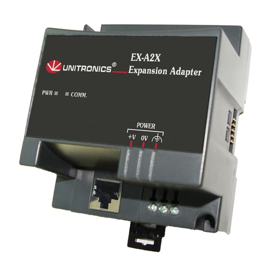
Component identification
1
Status indicators
2
COM port, EX-A2X to OPLC
3
Power supply connection points
4
EX-A2X to expansion module
connection port
Before using this product, it is the responsibility of the user to read and understand this document and
any accompanying documentation.
All examples and diagrams shown herein are intended to aid understanding, and do not guarantee
operation. Unitronics accepts no responsibility for actual use of this product based on these examples.
Please dispose of this product in accordance with local and national standards and regulations.
Only qualified service personnel should open this device or carry out repairs.
User safety and equipment protection guidelines
This document is intended to aid trained and competent personnel in the installation of this equipment as
defined by the European directives for machinery, low voltage, and EMC. Only a technician or engineer trained
in the local and national electrical standards should perform tasks associated with the device’s electrical wiring.
Symbols are used to highlight
information relating to the user’s
personal safety and equipment
protection throughout this document.
When these symbols appear, the
associated information must be read
carefully and understood fully.
Failure to comply with appropriate safety guidelines can result in severe personal injury or
property damage. Always exercise proper caution when working with electrical equipment.
Unitronics
Symbol
Meaning
Danger
Warning
Caution
Caution
5 / 2011
www.klinkmann.com
Description
The identified danger causes physical
and property damage.
The identified danger can cause
physical and property damage.
Use caution.
1
Advertisement
Table of Contents

Subscribe to Our Youtube Channel
Related Manuals for Unitronics EX-A2X


Summary of Contents for Unitronics EX-A2X
- Page 1 All examples and diagrams shown herein are intended to aid understanding, and do not guarantee operation. Unitronics accepts no responsibility for actual use of this product based on these examples. Please dispose of this product in accordance with local and national standards and regulations.
-
Page 2: Environmental Considerations
Do not place in water or let water leak onto the unit. Do not allow debris to fall inside the unit during installation. Mounting the Module DIN-rail mounting Snap the device onto the DIN rail as shown below; the module will be squarely situated on the DIN rail. Unitronics... -
Page 3: Screw-Mounting
To PLC and the other To Adapter; insert accordingly. The module is supplied with a 1-meter cable, part number EXL-CAB100. Other cable lengths are also available. Use only an original Unitronics cable and do not make any changes to it. Unitronics... -
Page 4: Connecting Expansion Modules
To avoid damaging the wire, do not exceed a maximum torque of 0.5 N·m (5 kgf·cm). Do not use tin, solder, or any other substance on stripped wire that might cause the wire strand to break. Install at maximum distance from high-voltage cables and power equipment. Unitronics... -
Page 5: Wiring Power Supply
A non-isolated power supply can be used provided that a 0V signal is connected to the chassis. Note that both the OPLC and the EX-A2X must be connected to the same power supply. The EX-A2X and the OPLC must be turned on and off simultaneously. - Page 6 I / O E x p a n s i o n M o d u l e Ad a p t e r , I s o l a t e d Notes: Example: 2 I/O-DI8-TO8 units consume a maximum of 140mA of the 5VDC supplied by the EX-A2X. Addressing I/Os on Expansion Modules Inputs and outputs located on I/O expansion modules that are connected to an OPLC are assigned addresses that comprise a letter and a number.
Need help?
Do you have a question about the EX-A2X and is the answer not in the manual?
Questions and answers