Table of Contents
Advertisement
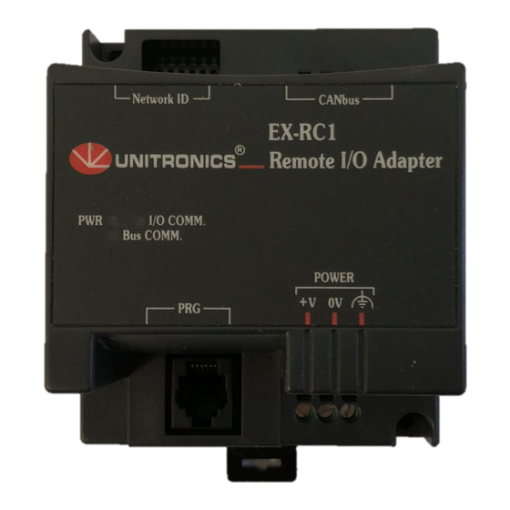
EX-RC1
Remote I/O Adapter
The EX-RC1 interfaces between Unitronics Vision OPLCs and remote I/O Expansion Modules distributed
throughout your system.
The adapter is connected to a PLC via CANbus. Each adapter may be connected to up to 8 I/O Expansion
Modules. The network may comprise up to 60 nodes, including both PLCs and adapters; note that the PLC
must comprise a CANbus port. Communication is via UniCAN, Unitronics' proprietary CANbus protocol.
The EX-RC1 is run by a factory-installed application. For more information refer to the Remote I/O topics in
the VisiLogic Help system.
The EX-RC1 may either be snap-mounted
on a DIN rail, or screw-mounted onto a
mounting plate.
Component identification
1
Status indicators
2
PC to EX-RC1 connection port
3
Power supply connection points
4
EX-RC1 to expansion module
connection port
5
CANbus port
6
DIP Switches
Before using this product, it is the responsibility of the user to read and understand this document and
any accompanying documentation.
All examples and diagrams shown herein are intended to aid understanding, and do not guarantee
operation. Unitronics accepts no responsibility for actual use of this product based on these examples.
Please dispose of this product in accordance with local and national standards and regulations.
Only qualified service personnel should open this device or carry out repairs.
User safety and equipment protection guidelines
This document is intended to aid trained and competent personnel in the installation of this equipment as
defined by the European directives for machinery, low voltage, and EMC. Only a technician or engineer trained
in the local and national electrical standards should perform tasks associated with the device's electrical wiring.
Symbols are used to highlight
information relating to the user's
personal safety and equipment
protection throughout this document.
When these symbols appear, the
associated information must be read
carefully and understood fully.
Unitronics
Network ID
PWR
I/O COMM.
Bus COMM.
PRG
Symbol
Meaning
Danger
Warning
Caution
Caution
CANbus
EX-RC1
Remote I/O Adapter
POWER
V
0V
Description
The identified danger causes physical
and property damage.
The identified danger can cause
physical and property damage.
Use caution.
1
Advertisement
Table of Contents

Related Manuals for Unitronics EX-RC1


Summary of Contents for Unitronics EX-RC1
- Page 1 Modules. The network may comprise up to 60 nodes, including both PLCs and adapters; note that the PLC must comprise a CANbus port. Communication is via UniCAN, Unitronics’ proprietary CANbus protocol. The EX-RC1 is run by a factory-installed application. For more information refer to the Remote I/O topics in the VisiLogic Help system.
-
Page 2: Environmental Considerations
Do not allow debris to fall inside the unit during installation. Mounting the Module DIN-rail mounting Snap the device onto the DIN rail as shown below; the module will be squarely situated on the DIN rail. Network ID CANbus EX-RC1 Remote I/O Adapter I/O COMM. Bus COMM. POWER Unitronics... -
Page 3: Screw-Mounting
R e m o t e I / O Ad a p t e r Screw-Mounting The figure below is not drawn to scale. It may be used as a guide for screw-mounting the module. Mounting screw type: either M3 or NC6-32. 80mm (3.15") 5.8mm 68.4mm (0.228") (2.693") (0.16") 4mm (x2) (0.16") Unitronics... -
Page 4: Connecting Expansion Modules
Do not connect the ‘Neutral or ‘Line’ signal of the 110/220VAC to the device’s 0V pin. In the event of voltage fluctuations or non-conformity to voltage power supply specifications, connect the device to a regulated power supply. Double-check all the wiring before turning on the power supply. Unitronics... -
Page 5: Wiring Procedures
Earthing the module’s power supply: connect one end of a 14 AWG wire to the chassis signal; connect the other end to the panel. Note: If possible, the wire used to earth the power supply should not exceed 10 cm in length. However, it is recommended to earth the module in all cases. POWER Unitronics... -
Page 6: Canbus Wiring
— Connecting the EX-RC1 to the CANbus network Connect the EX-RC1 adapter to an OPLC as shown below. The module communicates via Unitronics’ proprietary UniCAN protocol. UniCAN can comprise up to 60 nodes, including PLCs and EX-RC1 remote I/O adapters. -
Page 7: Network Layout
R e m o t e I / O Ad a p t e r Network Layout The EX-RC1 enables you to remotely locate I/Os up to 1 kilometer from a PLC. You can include both PLCs and adapters on the UniCAN network, up to a total of 60 nodes. - Page 8 EX- RC1 2/12 R e m o t e I / O Ad a p t e r EX-RC1 Technical Specifications Up to 8 I/O modules can be connected to a single adapter. The number of I/Os I/O module capacity may vary according to module.
Need help?
Do you have a question about the EX-RC1 and is the answer not in the manual?
Questions and answers