Vertiv Liebert EXS Installer/User Manual
Hide thumbs
Also See for Liebert EXS:
- User manual (121 pages) ,
- Installer/user manual (80 pages) ,
- Quick start manual (22 pages)
Table of Contents
Advertisement
Advertisement
Table of Contents

Related Manuals for Vertiv Liebert EXS


Summary of Contents for Vertiv Liebert EXS
- Page 1 Liebert® EXS™ Installer/User Guide 10-kVA, 60-Hz, 208/220-V, Three-phase UPS...
- Page 2 The products covered by this instruction manual are manufactured and/or sold by Vertiv. This document is the property of Vertiv and contains confidential and proprietary information owned by Vertiv. Any copying, use or disclosure of it without the written permission of Vertiv is strictly prohibited.
-
Page 3: Table Of Contents
3.2 Audible Alarm (Buzzer) 3.3 LCD Menu and Screens 3.3.1 Start-up and UPS Mimic Screens 3.3.2 Main Menu 3.4 Editing Display and Operation Settings 3.4.1 Changing the Password 3.4.2 Selecting the Display Language Vertiv | Liebert® EXS™ Installer/User Guide |... - Page 4 4.6 Transferring from Maintenance-bypass to Normal Mode 4.7 Remote Emergency Power-off (REPO) 5 Maintenance 5.1 Cleaning the UPS 5.2 Routine Maintenance 6 Optional Accessories 7 Specifications Appendices Appendix A: UPS Prompts and Alarms Vertiv | Liebert® EXS™ Installer/User Guide |...
-
Page 5: Important Safety Information
IMPORTANT SAFETY INFORMATION IMPORTANT! This manual contains important safety instructions that must be followed during the installation and maintenance of the UPS and batteries. Read this manual thoroughly and the safety and regulatory information, available at https://www.vertivco.com/ComplianceRegulatoryInfo, before attempting to install, connect to supply, or operate this UPS. - Page 6 This page intentionally left blank Vertiv | Liebert® EXS™ Installer/User Guide...
-
Page 7: Product Description
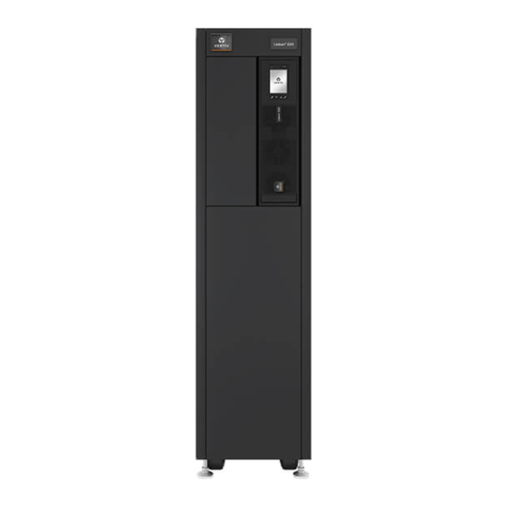
1 PRODUCT DESCRIPTION The Liebert® EXS™ uninterruptible power system (UPS) is an intelligent, online UPS with sine wave output. The UPS offers reliable, high-quality AC power to small-scale computer centers, networks, communication systems, automatic control systems, and similar sensitive electronic equipment. 1.1 Model Configurations Table 1.1 Model Configurations Model Rating... - Page 8 Figure 1.1 UPS Front and Rear View Vertiv | Liebert® EXS™ Installer/User Guide...
-
Page 9: Rear-Panel Components
1.3 Rear-panel Components Figure 1.2 Rear-panel Connectors Item Description REPO port USB port RS-232 port Parallel/LBS ports 1 Product Description... -
Page 10: Major Internal Components And Operating Principle
See Table 7.3 on page 55, for approximate run times. Batteries NOTE: To maintain battery design life, operate the UPS in an ambient temperature of 68°F to 77°F (20°C to 25°C). Maintenance Breaker electrically isolates the UPS and internal batteries for maintenance. Bypass Vertiv | Liebert® EXS™ Installer/User Guide... -
Page 11: Ups States And Operating Modes
Figure 1.3 UPS Operating-principle Item Description Bypass input Maintenance byass breaker Bypass input breaker Static switch Rectifier input Rectifier input breaker Rectifier Battery charger Battery Inverter Automatic inverter switch Output breaker UPS output 1.5 UPS States and Operating Modes NOTE: See Table 3.2 on page 32, for description of the run-indicator and alarm-indicator LEDs mentioned in this section. -
Page 12: Normal Mode
(green) is On, the alarm indicator is OFF, and the buzzer is silent. Figure 1.4 Normal-mode Operation Item Description Bypass input Maintenance byass breaker Bypass input breaker Static switch Rectifier input Rectifier input breaker Rectifier Battery charger Battery Inverter Automatic inverter switch Output breaker UPS output Vertiv | Liebert® EXS™ Installer/User Guide... - Page 13 Item Description Mains/Utility input (by-pass input) Rectifier/PFC Inverter Battery charger Battery Bypass static switch UPS output 1 Product Description...
-
Page 14: Battery Mode
(yellow) is On, and the buzzer beeps once each second. The LCD "Current" screen displays "On Battery." Figure 1.5 Battery-mode Operation Item Description Bypass input Maintenance byass breaker Bypass input breaker Static switch Rectifier input Rectifier input breaker Rectifier Battery charger Battery Inverter Automatic inverter switch Output breaker UPS output Vertiv | Liebert® EXS™ Installer/User Guide... -
Page 15: Bypass Mode
1.5.3 Bypass Mode Bypass mode supplies power to the load from the bypass source if an overload or fault occurs during normal operation. On the front-panel display, the run indicator (green) is On, the alarm indicator (yellow) is On, and the buzzer beeps once each second. The LCD "Current" screen displays "On Bypass." Figure 1.6 Bypass-mode Operation Item Description... -
Page 16: Auto Restart Mode
When enabled, which is the default setting, Auto Restart mode automatically re-starts the UPS after a shut-down that resulted from depleted batteries after an extended power outage. A built-in 10-second delay after utility power is restored allows other equipment to start first and stabilize before the UPS restarts. Vertiv | Liebert® EXS™ Installer/User Guide... -
Page 17: Eco Mode-Single Ups
1.5.5 Eco Mode—Single UPS The UPS ships in Eco mode as the factory-default setting. Eco mode reduces power consumption and provides UPS efficiency approaching 99% by powering the load via bypass if the bypass voltage is normal or by powering the load via the inverter when the bypass voltage is outside the specified range. NOTE: During Eco mode, if a bypass-failure or abnormal-bypass-voltage notification appears when the output is not overloaded, the UPS will transfer to Normal Mode. -
Page 18: Fault State
UPS shuts down and stops output power. During a Fault state, the front- panel display alarm indicator (red) is On, the buzzer beeps continuously, and fault information displays on the LCD screen. Vertiv | Liebert® EXS™ Installer/User Guide... -
Page 19: Maintenance Bypass Mode
UPS may shut down without notice and shut-off output power to the load. NOTE: The UPS has no user-serviceable parts. If the UPS malfunctions and requires service, visit http://www.VertivCo.com/en-us/support/ or contact your local Vertiv representative. Figure 1.8 Maintenance-bypass Operation... - Page 20 Item Description Inverter Automatic inverter switch Output breaker UPS output Vertiv | Liebert® EXS™ Installer/User Guide...
-
Page 21: Installation And Commissioning
2 INSTALLATION AND COMMISSIONING NOTE: These are general installation procedures and methods. Because each site is different, consider the site conditions and requirements when planning and conducting the installation. 2.1 Pre-installation Preparation Before beginning the installation, consider the environmental requirements, service clearances, and external protective devices when planning the final location of the UPS system. -
Page 22: Installation Tools
18-mm (23/32-in.) open wrench or adjustable wrench (Crescent wrench) • 16-mm (5/8-in.) wrench or socket • 13-mm (1/2-in.) wrench or socket • 10-mm (3/8-in.) wrench or socket • #1, #2, and #3 Phillips-head screwdrivers • Torque wrench Vertiv | Liebert® EXS™ Installer/User Guide... -
Page 23: Storage
2.1.4 Storage If you do not install the UPS immediately, you must store it indoors and protect it from excessive moisture, heat, and other harsh conditions. Store the batteries in a dry, well-ventilated environment with a temperature range of 68°F ~ 77°F (20°C ~ 25°C). NOTICE Risk of failure to properly charge batteries can damage the batteries and void the warranty. - Page 24 The UPS includes an overcurrent-protection device for the internal battery. UPS Output The UPS includes output overcurrent protection in all modes of operation. If the customer-provided output-distribution panel is not within sight of the UPS, the distribution panel must include a main breaker. Vertiv | Liebert® EXS™ Installer/User Guide...
-
Page 25: Equipment Handling And Unpacking
Upon receipt, check the items received against the order and shipping manifest. If any parts are missing, contact your local Vertiv representative or visit http://www.VertivCo.com/en-us/support/. The UPS ships on a pallet and is equipped with casters that permit two or more people to roll it off the pallet for installation. -
Page 26: Removing The Ups From The Shipping Pallet
6. Place the ramp onto the pallet at the front of the UPS, and gently roll the UPS down the ramp to the floor then into the installation position, see Figure 2.3 above. 7. Lower the leveling feet to fix the UPS in the location. Vertiv | Liebert® EXS™ Installer/User Guide... -
Page 27: Connecting Power Cables
2.3 Connecting Power Cables WARNING! Risk of electrical shock. Can cause equipment damage, injury and death. Before beginning installation, verify that all external overcurrent protection devices are open (Off), and that they are locked-out and tagged appropriately to prevent activation during the installation. After the power cables are connected, the terminal block’s protective cover must be reinstalled to remove the electric shock hazard. - Page 28 Table 2.2 on the previous page 6. Replace the wiring access cover plate and secure it. Figure 2.4 Single- and Dual-input Configuration Wiring Diagram Item Description Ground busbar AC-output terminals AC-input terminals Vertiv | Liebert® EXS™ Installer/User Guide...
-
Page 29: Connecting I/O Cables-Dual-Input Configuration
2.3.2 Connecting I/O Cables—Dual-input Configuration Dual input configuration for the UPS requires that both input feeds be from the same solid N-G bonded source. Prepare to connect the UPS power cables to the I/O terminal block on the UPS rear panel, see Figure 2.4 on the previous page: •... -
Page 30: Communication Connections
Provides dry-contact alarm information, including signals for: On Battery, On Bypass, Low Battery, Summary Liebert® IS-Relay Alarm, UPS Fault and On UPS for communication to a remote-monitoring system or network-connected Vertiv Card or third-party shut-down software. The card also accepts input signals to shut-down the UPS during any operating mode. -
Page 31: Repo Connection
2.4.2 REPO Connection Table 2.5 below, describes the pin-out of the REPO port, J14, used for N.O. or N.C. connection. Table 2.5 REPO port (J14) Pin Descriptions J14 Pin # Pin Name Description +5VDC REPO Power Supply, 5 VDC, 100mA REPO Coil N.C. -
Page 32: Connecting Usb Communication Cables
To connect the serial port communication cable, connect one end of the DB-9 serial-port communication cable to the DB-9 serial port on the rear panel of the UPS. Connect the other end to the computer’s DB-9 port. The port uses the RS-232 protocol. Vertiv | Liebert® EXS™ Installer/User Guide... - Page 33 Table 2.6 DB9F Pinout Description Pin No. Function TX (Send data) RX (Receive data) Common 2 Installation and Commissioning...
- Page 34 This page intentionally left blank Vertiv | Liebert® EXS™ Installer/User Guide...
-
Page 35: Operation And Display Panel
3 OPERATION AND DISPLAY PANEL The operation/display panel includes LED indicators, function keys, and an LCD interface to configure and control UPS operation. Figure 3.1 UPS Front-panel Display Item Description Run indicator LED, see LED Indicators on page 32. Alarm indicator LED, see LED Indicators on page 32. -
Page 36: Led Indicators
Table 3.2 LED Functions Indicator LED color LED state Indicates: UPS has output Run indicator Green Blinking Inverter is starting UPS has no output Yellow Alarm occurs Alarm indicator Fault occurs No alarm, no fault Vertiv | Liebert® EXS™ Installer/User Guide... -
Page 37: Audible Alarm (Buzzer)
3.2 Audible Alarm (Buzzer) An audible alarm accompanies various events during UPS operations. Table 3.3 below, describes the sounds and their meaning. To silence an alarm, see Silencing the Audible Alarm on page 41. Table 3.3 Audible-alarm Descriptions Sound Indicates: Continuous beep Generated when a UPS fault appears, such as a fuse or hardware failure. -
Page 38: Start-Up And Ups Mimic Screens
3.3.1 Start-up and UPS Mimic Screens At start-up, the UPS executes a system test and displays the Vertiv logo screen for 10 to 15 seconds, shown in Figure 3.1 on page 31. After the test completes, an overview screen shows status information, the active (green) power path, and the non-working power path (gray), see Figure 3.4 below. - Page 39 Status Screen The status screen displays voltages, currents, frequencies, and parameters on individual tabs for input, bypass, battery, output, and load status. To view the UPS status information: At the main menu, select the Status icon, and press Enter. 2. Use the arrow buttons to move the cursor left/right and select a tab, then press Enter to display the status information for the selected tab.
- Page 40 At the main menu, select the Log icon, and press Enter. 2. Use the arrow buttons to move the cursor left/right and select a tab, then press Enter to display the log for the selected tab. Figure 3.9 Current and History Log Tabs Vertiv | Liebert® EXS™ Installer/User Guide...
-
Page 41: Editing Display And Operation Settings
About Page The About screen offers tabs that list information about the product and the network. To view the product and network information: At the main menu, select the Settings icon, and press Enter. 2. Use the arrow buttons to move the cursor left/right and select a tab, then press Enter to display the information for the selected tab. - Page 42 Run Mode Normal, ECO Mode Normal ECO Voltage Range ±10% ±10% NOTE: ECO options appear only when in ECO mode ECO Frequency Range ±1.0Hz, ±2.0Hz, ±3.0Hz ±3.0Hz ECO Requalification Time 5, 15, 30 minutes Vertiv | Liebert® EXS™ Installer/User Guide...
-
Page 43: Changing The Password
Table 3.5 Settings Available at the Display Panel (continued) Settings Parameter range Default setting Shared Battery Disable, Enable Disable Local Battery total AH 9 - 36 Low Battery Time 2 – 30 minutes Battery Replaced Time YYYY-MM-DD HH:MM:SS 2000-01-01 00:00:00 Battery Test Interval Disable, 8, 12, 16, 20, 26 weeks Disable... -
Page 44: Selecting The Display Language
3. Use the arrow buttons to select the Monitor tab, then press Enter. 4. Use the down arrow to highlight Date or Time, then press Enter. 5. Use the up/down arrows to select the date/time, then press Enter to confirm. Vertiv | Liebert® EXS™ Installer/User Guide... -
Page 45: Operating The Ups
4 OPERATING THE UPS 4.1 Silencing the Audible Alarm If the audible alarm is enabled, it may sound during UPS operation. To silence the alarm, press and hold the ESC button for 3 seconds. The button is located on the front-panel display, see Operation and Display Panel on page 31. - Page 46 MBB (maintenance-bypass breaker) Ground busbar AC-output terminals AC-input terminals Breakers, see Figure 4.2 below. Ventilation holes Parallel/LBS port USB port REPO ports Figure 4.2 Rear-panel Breaker Layout Item Description MIB (output breaker) RIB (rectifier-input breaker) BIB (bypass-input breaker) Vertiv | Liebert® EXS™ Installer/User Guide...
-
Page 47: Ups Start-Up
4.2 UPS Start-up Perform start-up only after the UPS installation is complete, all UPS wiring is complete, and all exterior access panels that were removed for installation are replaced on the UPS. The start-up procedure starts the UPS in Normal Mode providing clean and protected AC power to the connected equipment. -
Page 48: Transferring From Normal (Inverter) To Bypass Mode
Use the up/down arrows to select no or yes, or press the ESC to cancel. b. Press Enter to confirm the action. Figure 4.4 Turn off inv—Bypass power in normal range Figure 4.5 Output shutdown—Bypass power outside normal range Vertiv | Liebert® EXS™ Installer/User Guide... -
Page 49: Transferring From Bypass To Normal (Inverter) Mode
4.4 Transferring from Bypass to Normal (Inverter) Mode To transfer to the inverter (normal operation) or turn on the UPS when the UPS is on internal bypass mode: Press and hold the power button for 2 seconds. • If the UPS is configured for normal operation, the option to turn-on the local inverter displays, see Figure 4.6 below. -
Page 50: Transferring To Maintenance-Bypass Mode
4.5 Transferring to Maintenance-bypass Mode The transfer procedure puts the UPS in maintenance-bypass mode for safe servicing by a Vertiv service technician. To transfer from normal operation to maintenance-bypass mode: Press and hold the power button for 2 seconds. •... -
Page 51: Remote Emergency Power-Off (Repo)
8. Select the operation Turn on UPS a. Select Turn on UPS. b. Press Enter to confirm the action. c. Press Enter again. 9. Locate the front-left panel set aside or on top the UPS, and replace it on the UPS. 4.7 Remote Emergency Power-off (REPO) The UPS is equipped with a remote emergency power-off (REPO) connector for normally-open (N.O.) or normally-closed (N.C.) systems. ... - Page 52 This page intentionally left blank Vertiv | Liebert® EXS™ Installer/User Guide...
-
Page 53: Maintenance
Vertiv representative. Battery Safety If the battery kit is damaged in any way or shows signs of leakage, contact Vertiv technical support immediately. Handle, transport, and recycle batteries in accordance with local regulations. WARNING! Risk of electrical shock. Can cause personal injury and death. When connected together, battery-terminal voltage is potentially lethal. - Page 54 Disposing of the waste lead-acid battery in a landfill or other waste dump can result in serious environment pollution and violates national and local laws. Vertiv has a service network and recycle system to assist in complying with laws governing waste battery disposal. Visit http://www.VertivCo.com/en-us/support/ for information about recycling the waste battery.
-
Page 55: Optional Accessories
6 OPTIONAL ACCESSORIES Table 6.1 Options List Option Part Number Description ITA2-PARACBL1M Parallel communication cable, 3 feet (1 meter) long ITA2-PARACBL3M Parallel communication cable, 9.8 feet (3 meters) long Parallel Communication Cable ITA2-PARACBL4M Parallel communication cable, 13 feet (4 meters) long ITA2-PARACBL10M Parallel communication cable, 32.8 feet (10 meters) long NOTE: One (1) parallel communication cable is required for each UPS in the parallel system. - Page 56 This page intentionally left blank Vertiv | Liebert® EXS™ Installer/User Guide...
-
Page 57: Specifications
7 SPECIFICATIONS Table 7.1 Specifications Liebert® EXS™ Model Item Description 10 kVA/kW Rated Voltage 208/120VAC or 220/127VAC; 3 Phase, 4W+Gnd Voltage Range 96-144VAC (L-N) Rated Frequency 60 Hz Input Frequency Range 40-70Hz Power Factor ≥0.99 at full load; ≥0.98 at half load Current Distortion THDi ≤5% Rated Power... - Page 58 36 x 48 x 60 (914.4 x 1219.2 x 1524) Weight, lbs (kg) Unit 437 (198.2) 627 (284.4) 893 (405.1) 1,093 (495.8) Shipping 487 (220.9) 677 (307.1) 1,011 (458.6) 1,211 (549.3) Color Black-Gray (RAL 7021) Vertiv | Liebert® EXS™ Installer/User Guide...
- Page 59 Table 7.3 Battery Run Time in Minutes—10-kVA Models Load Level 100% Battery- string 10kW 7.5kW 2.5kW Qty. Run times shown are approximate. They are based on new, fully-charged batteries at a temperature of 77°F (25°C) with 100% resistive UPS loading. Different loading will change the actual run times. Run times listed may vary by ±5% due to manufacturing variances of the batteries.
- Page 60 This page intentionally left blank Vertiv | Liebert® EXS™ Installer/User Guide...
-
Page 61: Appendices
The battery has reached End Of Discharge due to a Check the upstream input breaker(s) to ensure they are Battery EOD prolonged utility power outage and depletion of all closed and wait for input power to return or Contact Vertiv battery power Technical Support Battery low... - Page 62 Check the upstream input breaker(s) to ensure they are Battery to utility The load is powered by bypass (utility) power due to closed and wait for input power to return or Contact Vertiv transition depletion of battery power or battery failure...
- Page 63 Call a qualified electrician to verify the input ground Input PE lost conductor (PE) is missing or has been disconnected connection or Contact Vertiv Technical Support Input phase Call a qualified electrician to verify the input phase rotation The AC rectifier input phase rotation is reversed.
- Page 64 UPS has shut down due to activation of the REPO Check REPO circuit to reset it and manually restart the REPO circuit Restore factory The UPS was manually initiated to rest all settings to None required defaults the factory defaults from the display Vertiv | Liebert® EXS™ Installer/User Guide...
- Page 65 Internal temperatures have exceeded threshold Verify the ventilation openings are not block or Contact to overtemp settings and the UPS has shutdown Vertiv Technical Support The UPS model identification is not correct for the System fault Contact VertivTechnical Support firmware in the unit...
- Page 66 This page intentionally left blank Vertiv | Liebert® EXS™ Installer/User Guide...
- Page 67 Vertiv | Liebert® EXS™ Installer/User Guide...
- Page 68 VertivCo.com | Vertiv Headquarters, 1050 Dearborn Drive, Columbus, OH, 43085, USA © 2018 Vertiv Co. All rights reserved. Vertiv and the Vertiv logo are trademarks or registered trademarks of Vertiv Co. All other names and logos referred to are trade names, trademarks or registered trademarks of their respective owners. While every precaution has been taken to ensure accuracy and completeness herein, Vertiv Co.
Need help?
Do you have a question about the Liebert EXS and is the answer not in the manual?
Questions and answers