Vertiv Liebert EXS Installer/User Manual
15-40 kva, 60 hz, 208/220 v, three-phase ups
Hide thumbs
Also See for Liebert EXS:
- User manual (121 pages) ,
- Installer/user manual (68 pages) ,
- Quick start manual (22 pages)
Table of Contents
Advertisement
Quick Links
Advertisement
Table of Contents

Subscribe to Our Youtube Channel
Related Manuals for Vertiv Liebert EXS


Summary of Contents for Vertiv Liebert EXS
- Page 1 Liebert® EXS Installer/User Guide 15-40 kVA, 60 Hz, 208/220 V, Three-phase UPS...
- Page 2 The products covered by this instruction manual are manufactured and/or sold by Vertiv. This document is the property of Vertiv and contains confidential and proprietary information owned by Vertiv. Any copying, use, or disclosure of it without the written permission of Vertiv is strictly prohibited.
-
Page 3: Table Of Contents
3.4 Communication Connections 3.4.1 Liebert® intelliSlot™ ports 3.4.2 REPO connection 3.4.3 Connecting USB communication cables 3.4.4 Dry contact input and output connections 3.4.5 External device interface terminal connection ports 4 Operation and Display Panel Proprietary and Confidential ©2023 Vertiv Group Corp. - Page 4 6.4.7 Completely powering down the UPS 6.4.8 Procedures for complete UPS shutdown while maintaining power to load 6.5 LBS System 6.5.1 Overview 6.5.2 Cabinet installation 6.5.3 Connecting power cables 6.5.4 Connecting LBS cables 6.5.5 LBS parameters setting Proprietary and Confidential ©2023 Vertiv Group Corp.
- Page 5 Vertiv™ Liebert® EXS Installer/User Guide 6.5.6 LBS system commissioning 7 Maintenance 7.1 Cleaning the UPS 7.2 Routine Maintenance 7.2.1 Battery safety 8 Specifications Appendices Appendix A: Technical Support and Contacts Appendix B: UPS Prompts and Alarms Proprietary and Confidential ©2023 Vertiv Group Corp.
- Page 6 Vertiv™ Liebert® EXS Installer/User Guide This page intentionally left blank Proprietary and Confidential ©2023 Vertiv Group Corp.
-
Page 7: Important Safety Instructions
Where conductive dusts, corrosive gases, salts, or flammable gases are not present. • Away from heat sources or strong electromagnetic interferences. 1.2 Disclaimer Vertiv disclaims all responsibility and/or liability for any defects or malfunction caused by the following actions: • Application range or operating environment outside the specifications. •... -
Page 8: Safety Precaution
When operating Vertiv products, the operation personnel must observe the safety rules in the industry, the general safety points and special safety instructions provided by Vertiv. - Page 9 The specified upstream breakers are required to obtain the conditional short circuit current rating, Icc at 30 kA symmetrical rms. The specified upstream breakers should comply with a UL248 series standard. 1 Important Safety Instructions Proprietary and Confidential ©2023 Vertiv Group Corp.
- Page 10 WARNING! When the internal fuse of the UPS is damaged, it must be replaced with fuse of the same electric parameters from the designated manufacturer, and operated by qualified personnel. Proprietary and Confidential ©2023 Vertiv Group Corp. 1 Important Safety Instructions...
-
Page 11: Product Description
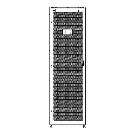
Vertiv™ Liebert® EXS Installer/User Guide 2 Product Description The Vertiv™ Liebert® EXS uninterruptible power system (UPS) is an intelligent, online UPS with sine wave output. The UPS offers reliable, high quality AC power to small scale computer centers, networks, communication systems, automatic control systems, and similar sensitive electronic equipment. - Page 12 Vertiv™ Liebert® EXS Installer/User Guide Figure 2.1 UPS Front and Side View Item Description Front view Right side view Right side view with optional power output distribution (POD) Proprietary and Confidential ©2023 Vertiv Group Corp. 2 Product Description...
-
Page 13: Inside Front Panel Components
Bypass input breaker (BIB) Maintenance bypass breaker (MBB) Vertiv™ Liebert® IntelliSlot™ ports Rectifier input breaker (RIB) Dry contact inputs Remote emergency power off (REPO) port Dry contact outputs Parallel/LBS ports 2 Product Description Proprietary and Confidential ©2023 Vertiv Group Corp. -
Page 14: Rear Panel Components
Vertiv™ Liebert® EXS Installer/User Guide 2.4 Rear Panel Components The Vertiv™ Liebert® EXS may include an optional power output distribution (POD) unit. Figure 2.3 Optional POD on Rear of UPS Item Description Proprietary and Confidential ©2023 Vertiv Group Corp. 2 Product Description... -
Page 15: Major Internal Components And Operating Principle
NOTE: To maintain battery design life, operate the UPS in an ambient temperature of 68 °F to 77 °F (20 °C to 25 °C). Maintenance bypass Breaker electrically isolates the UPS and internal batteries for maintenance. 2 Product Description Proprietary and Confidential ©2023 Vertiv Group Corp. -
Page 16: Ups States And Operating Modes
Maintenance isolation breaker (MIB) UPS output 2.6 UPS States and Operating Modes NOTE: See Table 4.2 on page 32, for description of the run indicator and alarm indicator LEDs mentioned in this section. Proprietary and Confidential ©2023 Vertiv Group Corp. 2 Product Description... -
Page 17: Normal Mode
Bypass input Maintenance byass breaker (MBB) Bypass input breaker (BIB) Static switch Rectifier input Rectifier input breaker (RIB) Rectifier Battery charger Battery Inverter Automatic inverter switch Maintenance isolation breaker (MIB) UPS output 2 Product Description Proprietary and Confidential ©2023 Vertiv Group Corp. -
Page 18: Battery Mode
Bypass input Maintenance bypass breaker (MBB) Bypass input breaker (BIB) Static switch Rectifier input Rectifier input breaker (RIB) Rectifier Battery charger Battery Inverter Automatic inverter switch Maintenance isolation breaker (MIB) UPS output Proprietary and Confidential ©2023 Vertiv Group Corp. 2 Product Description... -
Page 19: Bypass Mode
Bypass input Maintenance byass breaker (MBB) Bypass input breaker (BIB) Static switch Rectifier input Rectifier input breaker (RIB) Rectifier Battery charger Battery Inverter Automatic inverter switch Maintenance isolation breaker (MIB) UPS output 2 Product Description Proprietary and Confidential ©2023 Vertiv Group Corp. -
Page 20: Maintenance Bypass Mode
NOTE: The UPS has no user serviceable parts. If the UPS malfunctions and requires service, visit http://www.Vertiv.com/en-us/support/ or contact your local Vertiv representative. Figure 2.8 Maintenance Bypass Operation Item... -
Page 21: Auto Restart Mode
UPS will shutdown the bypass. Figure 2.9 Eco Mode Operation Item Description Bypass input Maintenance byass breaker (MBB) Bypass input breaker (BIB) 2 Product Description Proprietary and Confidential ©2023 Vertiv Group Corp. -
Page 22: Fault State
When the UPS is in battery mode (with no bypass utility), and the inverter fails or over temperature occurs, the UPS shuts down and stops output power. During a fault state, the front panel display alarm indicator (red) is On, the buzzer beeps continuously, and fault information displays on the LCD screen. Proprietary and Confidential ©2023 Vertiv Group Corp. 2 Product Description... -
Page 23: Installation And Commissioning
8.1 on page 59. 3.1.2 Clearance required for installation, maintenance, and operation Internal fans provide forced air cooling for the UPS. Cooling air enters through the front panel and hot air is exhausted through the back. 3 Installation and Commissioning Proprietary and Confidential ©2023 Vertiv Group Corp. - Page 24 If a top fan is installed and there is no POD, rear clearance is not required. Figure 3.1 Installation and Maintenance Clearances Item Description No side clearance required UPS (top view) No side clearance required Wall or other solid surface Proprietary and Confidential ©2023 Vertiv Group Corp. 3 Installation and Commissioning...
-
Page 25: Installation Tools
Table 3.2 on page 22. Dual input system protection In a dual input system, install separate protective devices for the utility and bypass at the utility input power distribution. 3 Installation and Commissioning Proprietary and Confidential ©2023 Vertiv Group Corp. -
Page 26: Equipment Handling And Unpacking
Maintain minimum tilt from vertical at all times. Slots at the base of the module cabinets are for forklift use. Forklift slots support the unit only if the forks are completely beneath the unit. Proprietary and Confidential ©2023 Vertiv Group Corp. 3 Installation and Commissioning... -
Page 27: Removing The Ups From The Shipping Pallet
Vertiv™ Liebert® EXS Installer/User Guide Upon receipt, check the items received against the order and shipping manifest. If any parts are missing or has noticeable damage, please notate this on the proof of delivery and contact your local Vertiv representative or visit http://www.Vertiv.com/en-us/support/. - Page 28 0 AWG (53.5 mm 3/0 AWG (85.3 mm 4/0 AWG (108.6 mm Manufacturer Part# Thomas and Betts: 54209 Thomas and Betts: 54211 Thomas and Betts: 54212 Recommended Torque 177 lb-in./14.7 lb-ft./20 Nm Proprietary and Confidential ©2023 Vertiv Group Corp. 3 Installation and Commissioning...
-
Page 29: Connecting I/O Cables
• Remove the wiring access cover plate to gain access to the input and output bus bar. NOTE: The Vertiv™ Liebert® EXS unit ships as a factory configured single input system. 3 Installation and Commissioning Proprietary and Confidential ©2023 Vertiv Group Corp. - Page 30 EBC connection . The quick installation guide is included with your battery cabinet and is available on the Vertiv™ Liebert® EXS product page at www.Vertiv.com. 8. Torque all customer side connections per recommendations in Table 3.3 on page 22, and Table 3.6 on the previous page.
- Page 31 Vertiv™ Liebert® EXS Installer/User Guide Figure 3.3 Connection Terminal Access and Locations Item Description Wiring access cover plate 15-30 K 40 K 3 Installation and Commissioning Proprietary and Confidential ©2023 Vertiv Group Corp.
-
Page 32: Communication Connections
Card Vertiv™ Liebert® IS-UNITY-SNMP™ Communicates via SNMP protocol to Vertiv montiring/shut down applications or any third party network management system. Card Vertiv™ Liebert® Communicates with upto two third party platforms including SNMP, Modbus, BACnet, and YDN-23 protocols to network connected IS-UNITY-DP Card Vertiv montiring/shut down applications or third party shut down software. -
Page 33: Repo Connection
Provides dry contact alarm information, including signals for: On Battery, On Bypass, Low Battery, Summary Alarm, UPS Fault and IS-RELAY Card On UPS for communication to a remote monitoring system or network connected Vertiv or third party shut down software. 3.4.2 REPO connection The Table 3.9 below, describes the pin out of the REPO port, J14, used for N.O. -
Page 34: Connecting Usb Communication Cables
3.4.3 Connecting USB communication cables The UPS includes a standard, USB Type-A port is provided for service and troubleshooting by Vertiv's service technicians. 3.4.4 Dry contact input and output connections The UPS contains 5 sets of configurable input contacts and 2 sets of configurable output contacts. Figure 2.2 on page 7, shows the dry contact location inside the front panel, and Figure 3.6 on the facing page, shows the connection details. - Page 35 Main Input Abnormal Output #2 N.O. • On Maintenance Bypass Summary Alarm • Load Shed Signal 1 • Load Shed Signal 2 Output #2 Gnd • Internal MBB Closed 3 Installation and Commissioning Proprietary and Confidential ©2023 Vertiv Group Corp.
-
Page 36: External Device Interface Terminal Connection Ports
However, the UPS includes all required back feed protection circuitry to comply with safety agency requirements. The capacity rating for J17 is 250 VAC, 5 A. Proprietary and Confidential ©2023 Vertiv Group Corp. 3 Installation and Commissioning... -
Page 37: Operation And Display Panel
Move to previous page, increase value, and move left. Down Move to next page, decrease value, and move right. Escape Go back. Power Power on the UPS, power off the UPS, and transfer to bypass mode. 4 Operation and Display Panel Proprietary and Confidential ©2023 Vertiv Group Corp. -
Page 38: Led Indicators
One 0.5 second beep every 1.5 seconds Generated when the UPS reaches low battery reserve. One 0.5 second beep every 1 second Generated when the UPS output is overloaded. Proprietary and Confidential ©2023 Vertiv Group Corp. 4 Operation and Display Panel... -
Page 39: Lcd Menu And Screens
4.3.1 Startup and UPS mimic screens At startup, the UPS executes a system test and displays the Vertiv logo screen for 10 to 15 seconds as shown in Figure 4.1 on page 31. After the test completes, an overview screen shows status information, the active (green) power path, and the non- working power path (gray). - Page 40 Product and network information. See About page page 37. Maintain Service only, proprietary password protected page for use only by Vertiv service representatives. Status screen The status screen displays voltages, currents, frequencies, and parameters on individual tabs for input, bypass, battery, output, and load status.
- Page 41 NOTE: To adjust the settings, you must enter a password. See Editing Display and Operation Settings page 38, for details on entering the password and editing the setting parameters. Figure 4.7 Monitor and System Tabs on the Settings Submenu 4 Operation and Display Panel Proprietary and Confidential ©2023 Vertiv Group Corp.
- Page 42 2. Use the arrow buttons to move the cursor left/right and select a tab, then press Enter to display the log for the selected tab. Figure 4.9 Current and History Log Tabs Proprietary and Confidential ©2023 Vertiv Group Corp. 4 Operation and Display Panel...
- Page 43 2. Use the arrow buttons to move the cursor left/right and select a tab, then press Enter to display the information for the selected tab. Figure 4.10 About Screen Tabs 4 Operation and Display Panel Proprietary and Confidential ©2023 Vertiv Group Corp.
-
Page 44: Editing Display And Operation Settings
1200 bps, 2400 bps, 4800 bps, 9600 bps, 19200 bps 9600 bps UPS Comm Address Card Slot Protocol YDN23, Velocity Velocity Change Settings 0–9, must be six digits in length 111111 Password Proprietary and Confidential ©2023 Vertiv Group Corp. 4 Operation and Display Panel... -
Page 45: Changing The Password
4. Use the down arrow to highlight Language, then press Enter. 5. Use the up/down arrows to select the language, then press Enter. All the LCD elements display in the selected language. 4 Operation and Display Panel Proprietary and Confidential ©2023 Vertiv Group Corp. -
Page 46: Setting The Date And Time
3. Use the arrow buttons to select the Monitor tab, then press Enter. 4. Use the down arrow to highlight Date or Time, then press Enter. 5. Use the up/down arrows to select the date/time, then press Enter to confirm. Proprietary and Confidential ©2023 Vertiv Group Corp. 4 Operation and Display Panel... -
Page 47: Operating The Ups
9. After the system checks are complete and/or operating parameters are set, press the power button at the front panel display, then use the up/down arrow buttons to confirm Turn on local INV. See Figure 5.1 on the next page. 5 Operating the UPS Proprietary and Confidential ©2023 Vertiv Group Corp. -
Page 48: Transferring From Normal (Inverter) To Bypass Mode
Use the up/down arrows to select no or yes, or press the ESC to cancel. b. Press Enter to confirm the action. Figure 5.2 Turn Off INV—Bypass Power in Normal Range Proprietary and Confidential ©2023 Vertiv Group Corp. 5 Operating the UPS... -
Page 49: Transferring From Bypass To Normal (Inverter) Mode
Use the up/down arrows to select no or yes, or press the ESC to cancel. b. Press Enter to confirm the action. Figure 5.4 Turn On Local INV 5 Operating the UPS Proprietary and Confidential ©2023 Vertiv Group Corp. -
Page 50: Transferring To Maintenance Bypass Mode
Figure 5.5 Transfer with Interrupt 5.5 Transferring to Maintenance Bypass Mode The transfer procedure puts the UPS in maintenance bypass mode for safe servicing by a Vertiv service technician. To transfer from normal operation to maintenance bypass mode: Press and hold the Power button for 2 seconds. -
Page 51: Repo
The UPS is equipped with a REPO connector for N.O. or N.C. systems. See REPO connection on page 27, for connection details. Consult national and local wiring codes to determine if additional REPO is required for the external UPS rectifier and bypass feeds. 5 Operating the UPS Proprietary and Confidential ©2023 Vertiv Group Corp. - Page 52 Vertiv™ Liebert® EXS Installer/User Guide This page intentionally left blank Proprietary and Confidential ©2023 Vertiv Group Corp. 5 Operating the UPS...
-
Page 53: Parallel System And Lbs System
UPS should follow the installation procedure for a single UPS module with the additional requirements detailed in this section. WARNING! To achieve normal operation of the parallel system, Vertiv service personnel must execute the CAN resistance operation. Failure to do so could result in system fault. -
Page 54: Cabinet Installation
PARALLEL1 port to the PARALLEL2 port of another module. Repeat this step for all the other parallel cables. The ring connection ensures the reliability of the control of the parallel system. Make sure that the cables are securely connected before starting the system. Proprietary and Confidential ©2023 Vertiv Group Corp. 6 Parallel System and LBS System... -
Page 55: Repo
Figure 6.3 EPO Circuit Diagram NOTE: In Figure 6.3 above, the upper one is normally open type, and the lower one is normally closed type. 6 Parallel System and LBS System Proprietary and Confidential ©2023 Vertiv Group Corp. -
Page 56: Operation Procedures For Parallel System
6.4.2 Parallel system parameters setting NOTE: The parameters of parallel system must be set by Vertiv engineer through Vertiv setting software. 6.4.3 Power on procedures for parallel system WARNING! During the parallel power on, confirm that the external output MCB of each UPS has been closed, and that all the inverter output of the UPSs is connected parallelly. -
Page 57: Maintenance Bypass Procedures
WARNING! The parts of UPS circuits also have hazardous voltage, though the rectifier input switch, bypass input switch and battery switch are disconnected. Therefore, the UPS maintenance is applicable to qualified personnel only. 6 Parallel System and LBS System Proprietary and Confidential ©2023 Vertiv Group Corp. -
Page 58: Isolating One Ups Module From Parallel System
6.4.5 Isolating one UPS module from parallel system WARNING! These procedures shall only be carried out by service personnel of Vertiv or under their guidance. WARNING! Before operation, confirm that the system capacity has redundancy to avoid system shutdown due to overload. -
Page 59: Inserting One Isolated Ups Module In Parallel System
6.4.6 Inserting one isolated UPS module in parallel system WARNING! These procedures shall only be carried out by service personnel of Vertiv or under their guidance. The following procedures are used to reintegrate a UPS module that has been previously isolated from the parallel system: If the UPS is equipped with internal batteries, ensure that the external battery terminals are well connected. -
Page 60: Procedures For Complete Ups Shutdown While Maintaining Power To Load
Refer to Figure 6.4 below and Figure 6.5 on the facing page for details. Figure 6.4 LBS System (UPS Module) Proprietary and Confidential ©2023 Vertiv Group Corp. 6 Parallel System and LBS System... -
Page 61: Connecting Power Cables
Connect the shielded and double insulated LBS optional cables (5 m, 10 m, and 15 m) between the LBS port of the two UPS systems as shown in Figure 6.6 below and Figure 6.7 on the next page. Figure 6.6 Connection of Typical LBS System (UPS Module) 6 Parallel System and LBS System Proprietary and Confidential ©2023 Vertiv Group Corp. -
Page 62: Lbs Parameters Setting
Vertiv™ Liebert® EXS Installer/User Guide Figure 6.7 Connection of Typical LBS System (Parallel System) 6.5.5 LBS parameters setting NOTE: The parameters of LBS parameters must be set by Vertiv engineer through Vertiv setting software. 6.5.6 LBS system commissioning Refer to Operation Procedures for Parallel System on page 50 for details. -
Page 63: Maintenance
7.2 Routine Maintenance There are no user serviceable parts in the UPS. Attempting to service the unit yourself can void the warranty. Any routine maintenance other than cleaning, must be performed by a Vertiv service technician. Visit http://www.Vertiv.com/en-us/support/, or contact Vertiv representative. -
Page 64: Battery Safety
Vertiv™ Liebert® EXS Installer/User Guide 7.2.1 Battery safety If the battery kit is damaged in any way or shows signs of leakage, contact Vertiv technical support immediately. Handle, transport, and recycle batteries in accordance with local regulations. CAUTION: Do not dispose of the battery in a fire. The battery may explode. -
Page 65: Specifications
110% to 125% 10 Minutes Bypass Overload Capabilities 125% to 150% 1 Minutes >150% (impact load) No less than 200 ms 1000% 100 ms AC-AC Efficiency Up to 93.4% online mode, 98.7% ECO mode 8 Specifications Proprietary and Confidential ©2023 Vertiv Group Corp. - Page 66 Operation of this equipment in a residential area is likely to cause harmful interference in such case the user is required to correct the interference at his own expense. Proprietary and Confidential ©2023 Vertiv Group Corp. 8 Specifications...
- Page 67 15 kW 12 kW 10 kW 8 kW 6 kW 5 kW 2 kW 11.5 13.5 19.5 25.5 31.5 90.5 204.5 32.5 45.5 69.5 193.5 428.5 51.5 66.5 117.5 148.5 317.5 672.5 8 Specifications Proprietary and Confidential ©2023 Vertiv Group Corp.
- Page 68 15 kW 12 kW 10 kW 8 kW 6 kW 5 kW 2 kW 15.5 18.5 36.5 48.5 70.5 257.5 41.5 47.5 64.5 96.5 123.5 171.5 584.5 71.5 80.5 136.5 162.5 906.5 Proprietary and Confidential ©2023 Vertiv Group Corp. 8 Specifications...
-
Page 69: Appendices
24x7 dispatch of technicians for all products. 1-800-543-2378 Liebert® Thermal Management Products 1-800-543-2378 Liebert® Channel Products 1-800-222-5877 Liebert® AC and DC Power Products 1-800-543-2378 A.2 Locations United States Vertiv Headquarters 505 N Cleveland Ave Appendices Proprietary and Confidential ©2023 Vertiv Group Corp. - Page 70 Vertiv™ Liebert® EXS Installer/User Guide Westerville, OH 43082 Europe Via Leonardo Da Vinci 8 Zona Industriale Tognana 35028 Piove Di Sacco (PD) Italy Asia 7/F, Dah Sing Financial Centre 3108 Gloucester Road, Wanchai Hong Kong Proprietary and Confidential ©2023 Vertiv Group Corp. Appendices...
-
Page 71: Appendix B: Ups Prompts And Alarms
Appears when the power button is pressed on a unit in a parallel system. Select one option to confirm operation. Turn ON PARA INV Turn OFF local INV Appears when the power button is pressed on a unit in a parallel system. Select one option to confirm operation. Turn OFF PARA INV Proprietary and Confidential ©2023 Vertiv Group Corp. - Page 72 Bypass backfeed A bypass short circuit has been detected while in battery mode. Contact Vertiv Technical Support. Bypass Input The bypass switch is opened. None required Breaker Open Proprietary and Confidential ©2023 Vertiv Group Corp.
- Page 73 The UPS remains on inverter power due to exceeding the preset Excess ECO Auto number of transfers within a 1 hour period while in ECO mode Check input power or contact Vertiv Technical Support. Transfers operation. External MBB The external maintenance bypass switch is closed.
- Page 74 Intelligent ECO mode enabled. None required Enabled Internal MBB Closed The maintenance bypass switch is closed. The UPS is being serviced, the load is not protected. Internal MBB Open The maintenance switch is opened. None required Proprietary and Confidential ©2023 Vertiv Group Corp.
- Page 75 Verify the parallel system settings, remove unauthorized Exceeded system settings. loads, or contact Vertiv Technical Support. Power button is pressed on one UPS, and select the parallel system MMS Inv. Manual Off None required for unified shutdown. Proprietary and Confidential ©2023 Vertiv Group Corp.
- Page 76 EEPROM operation failed during DSP configuration, or DSP parameter Contact Vertiv Technical Support. Fail issued by MON failed. Power Hardware The model information set at the host is inconsistent with the actual Contact Vertiv Technical Support. Mismatch situation. Proprietary and Confidential ©2023 Vertiv Group Corp.
- Page 77 Testing Mode Testing mode enabled. None required Enabled Check event log for reason contact Vertiv Technical Turn On Fail The inverter failed to turn on when the Inverter Manual On is pressed. Support. Proprietary and Confidential ©2023 Vertiv Group Corp.
- Page 78 Vertiv™ Liebert® EXS Installer/User Guide This page intentionally left blank Proprietary and Confidential ©2023 Vertiv Group Corp.
- Page 79 Vertiv™ Liebert® EXS Installer/User Guide...
- Page 80 Vertiv.com | Vertiv Headquarters, 505 N Cleveland Ave, Westerville, OH 43082 USA ©2023 Vertiv Group Corp. All rights reserved. Vertiv™ and the Vertiv logo are trademarks or registered trademarks of Vertiv Group Corp. All other names and logos referred to are trade names, trademarks or registered trademarks of their respective owners. While every precaution has been taken to ensure accuracy and completeness here, Vertiv Group Corp.
Need help?
Do you have a question about the Liebert EXS and is the answer not in the manual?
Questions and answers