GW Instek LCR-800 Series User Manual
Hide thumbs
Also See for LCR-800 Series:
- User manual (40 pages) ,
- User manual (91 pages) ,
- User manual (42 pages)
Table of Contents
Advertisement
LCR-800 Series User Manual
CONTENTS
1.
INTRODUCTION..................................................... 1
2.
PRECAUTIONS BEFORE OPERATION.......................
2-1.Unpacking the instrument......................................
2-2.Checking the Line Voltage......................................
2-3.Environment.......................................................
2-4.Equipment Installation, and Operation.....................
3.
PANEL DESCRIPTION..............................................
4.
OPERATION...........................................................
4-1.Connects to DUT...................................................
4-2.Start-Up..............................................................
4-3.Zeroing.............................................................
4-4.Menu Functions...................................................
4-5.Measurement Condition.........................................
SPECIFICATIONS................................................... 35
5.
6.
MESSAGE CODE..................................................... 42
7.
MAINTENANCE....................................................... 43
8.
8-1. BIN Functions for Components Sorting.....................
8-2. BIN Setting Conditions:.........................................
8-3. BIN Range Setting: Component Sorting Range..............
9.
OPTION 2 (RS-232, for LCR-816/817/819 only)............... 61
i
PAGE
2
2
2
3
3
4
8
8
8
8
11
18
44
44
46
52
Advertisement
Table of Contents

Related Manuals for GW Instek LCR-800 Series


Summary of Contents for GW Instek LCR-800 Series
-
Page 1: Table Of Contents
LCR-800 Series User Manual CONTENTS PAGE INTRODUCTION……………………………………..……... 1 PRECAUTIONS BEFORE OPERATION…….……………. 2-1.Unpacking the instrument………………….……………. 2-2.Checking the Line Voltage…………………..…………… 2-3.Environment……………………………………..……….. 2-4.Equipment Installation, and Operation………………… PANEL DESCRIPTION…...……………………..………….. OPERATION…………….………………………………...…. 4-1.Connects to DUT….………………..………….……..…... 4-2.Start-Up………..……………………………..…………. 4-3.Zeroing……………………………………………………. 4-4.Menu Functions.…..……………………………………… 4-5.Measurement Condition…..……………………………... SPECIFICATIONS…………………………………………... 35 MESSAGE CODE.…………………………………………..42 MAINTENANCE..…………………………………………... - Page 2 LCR-800 Series User Manual SAFETY TERMS AND SYMBOLS These terms may appear in this manual or on the product: WARNING: Warning statements identify condition or practices that could result in injury or loss of life. CAUTION: Caution statements identify conditions or practices that could result in damage to this product or other property.
- Page 3 LCR-800 Series User Manual FOR UNITED KINGDOM ONLY NOTE: This lead / appliance must only be wired by competent persons WARNING: THIS APPLIANCE MUST BE EARTHED IMPORTANT: The wires in this lead are coloured in accordance with the following code:...
- Page 4 LCR-800 Series User Manual EC Declaration of Conformity GOOD WILL INSTRUMENT CO., LTD. No. 95-11, Pao-Chung Rd., Hsin-Tien City, Taipei Hsien, Taiwan declares that the below mentioned product LCR-817/819/827/829/816/826 are herewith confirmed to comply with the requirements set out in the Council...
-
Page 5: Introduction
LCR-800 Series User Manual 1. INTRODUCTION The precise LCR meter series are automatic, user programmable instruments that provide high reliability and great precision for measuring a wide variety of impedance parameters. The frequency range of LCR-819/829 covers from 12Hz to 100kHz, LCR-817/827 from 12Hz to 10kHz, and LCR-816/826 from 100Hz to 2kHz. -
Page 6: Precautions Before Operation
LCR-800 Series User Manual 2. PRECAUTIONS BEFORE OPERATION 2-1. Unpacking the instrument The product has been fully inspected and tested before shipping from the factory. Upon receiving the instrument, please unpack and inspect it to check if there are any damages caused during transportation. If any damage is found, notify the bearer and/or the dealer immediately. -
Page 7: 2-3.Environment
LCR-800 Series User Manual 2-3. Environment The normal ambient temperature range of the LCR Meters is from 10° to 50°C. To operate the instrument over this specific temperature range may cause damage to the circuits. Do not use the LCR Meters in a place where strong magnetic or electric field exists as it may disturb the measurement. -
Page 8: Panel Description
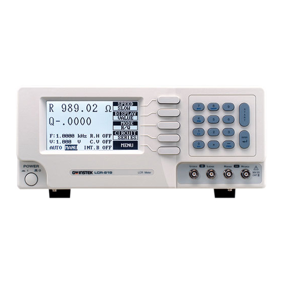
LCR-800 Series User Manual 3. PANEL DESCRIPTION (1). Power Switch Turns AC Power on or off. (2). Function key F1 Soft key functions as indicated on the adjacent LCD monitor. (3). Function key F2 Soft key functions as indicated on the adjacent LCD monitor. - Page 9 LCR-800 Series User Manual (10). Compound key For making numerical entries as labeled. Selects the “INTERNAL BIAS” mode or “EXTERNAL BIAS” mode. (If this key function is switched to “INTERNAL BIAS” mode, the bottom of LCD monitor will display the “INT.B” message. If the external DC bias is selected, the bottom of LCD monitor will display the “EXT.B”...
- Page 10 LCR-800 Series User Manual This line can display the measured Quality Factor or Dissipation or ESR or EPR. (23). Instrument status or indicates measurement results based on entered test limits. (24). Test conditions (25). Input terminals BNC connectors, connects to device under test (DUT).
- Page 11 LCR-800 Series User Manual FRONT PANEL...
-
Page 12: Operation
LCR-800 Series User Manual 4. OPERATION 4-1. Connects to DUT The LCR Meters utilize the structure of four wires measurement which allows accurate, easy, and stable measurements and avoids mutual inductance and interference from measurement signals, noise and other factors inherent with other types of connections. - Page 13 LCR-800 Series User Manual After the BAR at the bottom of LCD monitor is filled to the full, the zeroing process is done. If the zeroing process is successful, a message of “OK” will appear on the LCD monitor. If failed, a message of “FAIL” will appear on the LCD monitor.
- Page 14 LCR-800 Series User Manual SPEED L 1.2345H SLOW DISPLAY Q 0.6789 VALUE MODE TESTING CIRCUIT Press menu SERIES F : 1.000 kHz R.H OFF V : 1.000 V C.V OFF MENU AUTO MANU INT.B OFF Press F1 key to the zeroing CAP.
-
Page 15: 4-4.Menu Functions
LCR-800 Series User Manual 4-4. Menu Functions All the LCR Meters’ programmable functions are controlled by the easy to use menu displays. User can enter the menu mode by selecting the MENU key that calls up four top level menus, OFFSET, SORT, SETTING and CALBRAT. - Page 16 LCR-800 Series User Manual Primary Secondary Display Display SPEED L 1.2345H SLOW DISPLAY Q 0.6789 Press F3 key VALUE successively in order MODE to select the different measurement mode TESTING CIRCUIT (L/Q, C/D, C/Q, R/Q) SERIES F : 1.000 kHz R.H OFF...
- Page 17 LCR-800 Series User Manual Unless for special reason, always select “Series” for capacitors and inductors. This has traditionally been standard practice. For very small capacitance or inductance, select a higher test frequency for better accuracy. For very large capacitance or inductance, select a lower test frequency for better accuracy. For dc resistance, select a lower test frequency to minimize ac effects.
- Page 18 LCR-800 Series User Manual The measured results of the LCR Meters can be shown on the LCD monitor in three ways: VALUE, DELTA%, or DELTA. User can press F2 key to select the appropriate item for measurement. VALUE The LCD monitor will display the measured value of both the primary and secondary parameter, shown with decimal and units.
- Page 19 LCR-800 Series User Manual DELTA% The “DELTA%” shows the percent deviation of the measured L, C, or R value from a stored NOMINAL VALUE. The sign of deviation is indicated. DELTA The LCR difference is similar to the DELTA% except that the deviation is shown in suitable units (ohms, henries, etc).
- Page 20 LCR-800 Series User Manual Steps of “Nominal Value” input (Figure 4-6): Press MENU key. Press F2 key to select “SORT” menu. Press F1 key to select “Nominal Value” (the “NOM.VAL” is indicated on the adjacent LCD monitor). Input the nominal value via the numeral keys (5 digits with decimal maximum).
- Page 21 LCR-800 Series User Manual SPEED L 1.2345H SLOW DISPLAY Q 0.6789 VALUE MODE TESTING CIRCUIT Press menu SERIES F : 1.000 kHz R.H OFF V : 1.000 V C.V OFF MENU AUTO MANU INT.B OFF CAP. R/L OFFSET Press F2 key...
-
Page 22: 4-5.Measurement Condition
LCR-800 Series User Manual Press F1 key to select the three different measurement speed. (SLOW, MEDIUM, or FAST) SPEED L 1.2345H SLOW DISPLAY Q 0.6789 VALUE MODE TESTING CIRCUIT SERIES F : 1.000 kHz R.H OFF V : 1.000 V C.V OFF... - Page 23 LCR-800 Series User Manual Press the numerical 7 key Press the numerical 8 key to to select either internal or turn either internal or external external bias voltage bias voltage on or off. BIAS ON/OFF FREQ SPEED L 1.2345H SLOW DISPLAY Q 0.6789...
- Page 24 LCR-800 Series User Manual Steps of “BIAS” voltage selection (Figure 4-8, please note that the models of LCR-816 and 826 do not have this function): Press compound key 7 to selects the “INTERNAL BIAS” or “EXTERNAL BIAS” on the main menu. (If this key function is switched to “INTERNAL BIAS”, the bottom of LCD monitor will display the “INT.B”...
- Page 25 LCR-800 Series User Manual BIAS ON/OFF FREQ Press - key to input test Press enter key to confirm the frequency inputs. SPEED L 1.2345H SLOW DISPLAY Q 0.6789 VALUE MODE TESTING CIRCUIT SERIES F : 1.000 kHz R.H OFF V : 1.000 V C.V OFF...
- Page 26 LCR-800 Series User Manual 4-5-3. D/Q in PPM (parts per million) If the value of D or Q is less than 0.0100, user can select DQ in PPM to improve the resolution by a factor of 100. The units of D and Q in PPM are dimensionless and expressed as a decimal ratio with the multiplier of 1000000.
- Page 27 LCR-800 Series User Manual SPEED L 1.2345H SLOW DISPLAY Q 0.6789 VALUE MODE TESTING CIRCUIT Press menu SERIES F : 1.000 kHz R.H OFF V : 1.000 V C.V OFF MENU AUTO MANU INT.B OFF Test Voltage CAP. R/L OFFSET...
- Page 28 LCR-800 Series User Manual 4-5-6. Range Hold If a DUT is removed from the test cable or fixture during the “Continuous” mode, the feature of “Range Hold” can avoid range switching. Due to the test time can be reduced, “Range Hold” is a useful utility for repetitive devices measurement.
- Page 29 LCR-800 Series User Manual SPEED L 1.2345H SLOW DISPLAY Q 0.6789 VALUE MODE TESTING CIRCUIT Press menu SERIES F : 1.000 kHz R.H OFF V : 1.000 V C.V OFF MENU AUTO MANU INT.B OFF CAP. R/L OFFSET OFFSET SET SORT...
- Page 30 LCR-800 Series User Manual 4-5-8. Memory The LCR Meters have two memory functions: Recall and Store. The current measurement conditions can be saved into the memory unit or recalled a previously saved measurement conditions set from the LCR Meters memory.
- Page 31 LCR-800 Series User Manual SPEED L 1.2345H SLOW DISPLAY Q 0.6789 VALUE MODE TESTING CIRCUIT Press menu SERIES F : 1.000 kHz R.H OFF V : 1.000 V C.V OFF MENU AUTO MANU INT.B OFF CAP. R/L OFFSET OFFSET SET SORT...
- Page 32 LCR-800 Series User Manual Press compound key 1 to select Press compound key 2 to select the memory recall function the memory store function MOMORY (1)RECALL:(2)STORE VOLT VOLTAGE = 1.000 V 1.000 AVGE AVERAGE = 1 EXIT Input number of desired memory block for memory recall function...
- Page 33 LCR-800 Series User Manual 4-5-9. Handler Interface(Only for LCR-826/827/829) HANDLER FUNCTION INTERFACE Signal Name Pin NO. Start Measurement(I) /I_E_TRIG End of test(O) /O_EOM Data acquisition over , DUT removal OK.(O) /O_INDEX RLC FAIL(O) /O_P_HI /O_P_LO /O_P_OVER No-Go , D or Q Fail...
- Page 34 LCR-800 Series User Manual High /BIN1-/BIN9 /AUX_BIN /OUT_OF_BIN /PHI 0.5V +5V +24V /PLO Control Signals /INDEX /EOM * R408 R427 Pull-high Resistor need to be changed. Handler Interface Typical Electrical Characteristics Input Current (Low) Input Note Pull-high Voltage Comparison Signals...
- Page 35 LCR-800 Series User Manual Measurement Complete signal: /O_INDEX: This signal will go the low level when analog measurement is completed and will go the high level when next trigger is active. The handler can then remove the DUT from the fixture and replace it with another DUT during the time when /O_INDEX is at low level.
- Page 36 LCR-800 Series User Manual...
- Page 37 LCR-800 Series User Manual 4-5-10. Handler Interface Timing(only for LCR-826/827/829)
- Page 38 LCR-800 Series User Manual /O_BIN_1-_BIN_13,/O_P_OVER,/O_S_OVER,/O_S_REJ,/O_P_HI,/O_P_LO * DATA: Time Minimum Maximum Value Value T1 Trigger Pulse Width 5 us T2 Measurement Start 140 us Delay Time T3 /EOM Delay Time 5 us After Data Output Calculation and 6 ms binning Time...
-
Page 39: Specifications
LCR-800 Series User Manual 5. SPECIFICATIONS Measurement Parameters: Inductance (L , Capacitance (C ), Resistance (R ), Dissipation (D), Quality Factors (Q), Equivalent Series Resistance (ESR) and Equivalent Parallel Resistance (EPR). Measurement Models: Four kinds of measurement model can be selected. Two measurement parameters measured and displayed simultaneously. - Page 40 LCR-800 Series User Manual Accuracy: R, L, C: 0.05% (Basic) D, Q: 0.0005 (Basic) *LCR-816/826/827/829 is one fold less accuracy than LCR-817/819. (LCR-816/826: 0.2%, LCR-827/829: 0.1%, LCR-817/819: 0.05%) Test Frequency: There are 503 test frequencies between 12Hz and 100kHz that can be selected by using keypad for LCR-819/829.
- Page 41 LCR-800 Series User Manual Measurement Modes: Two modes are available: AUTO and MANUAL. “AUTO” mode is measuring continuously, updating the display after each measurement. “MANUAL” mode is activated by the START keypad, the measured result is holding on the LCD monitor until next measurement started.
- Page 42 LCR-800 Series User Manual Operation Environment: Indoor use, Altitude up to 2000M Installation Category II Pollution Degree Operating temperature: 10 50 , < 85% relative humidity Storage temperature: 20 AC Power Source: AC 100 240V, 50Hz 60Hz Power Consumption: 45 Watts maximum...
- Page 43 LCR-800 Series User Manual The Error value of LCR-817/819 (Double the error value for LCR-827/829, 4 times the error value for LCR-816/826) The formula for primary readout accuracy of C, R, and L. C: 0.03% + 0.02% [ (1+Ka) or (X/Ymax )
- Page 44 LCR-800 Series User Manual Kc: Frequency & RMS Voltage factor (refer to Table A) X: X is value of the component being tested. Y: Y is range constant (refer to Table B) Rx and Cx are value of the component being tested.
- Page 45 LCR-800 Series User Manual Table A: (for range 4)-Kc Voltage 0.03 V 0.1 0.1 V 0.25 0.25 V 1 1 V 1.265 Frequency 0.012 F 0.03 0.030 F 0.1 0.1 F 0.25 0.25 F 1 1 F 3 3 F 6...
-
Page 46: Message Code
LCR-800 Series User Manual 6. MESSAGE CODE This section describes the message code for the LCR Meters. OVER-01 Cause: 1. If the impedance of “Device-under-test” is small than the existing measurement range of the LCR Meters, the “OVER-01” message will be displayed on the LCD monitor. -
Page 47: Maintenance
LCR-800 Series User Manual 7. MAINTENANCE This section includes the basic maintenance information for the LCR Meters. 7-1. Cleaning Remove the AC input power (disconnect and remove the power cord) from the LCR Meters before attempting to clean the instrument. -
Page 48: Option 1 (Bin Function For Lcr-826/827/829 Only)
LCR-800 Series User Manual 8. OPTION 1 BIN Functions, only for LCR-826/827/829 8-1. BIN FUNTIONS for Components Sorting: Proceed BIN FUNTIONS steps Figure 8-1 : Press MENU key. Press F2 key to select “SORT” function. Press F2 key to select “OPTION1 ” function. - Page 49 LCR-800 Series User Manual SPEED C 13.450uF SLOW DISPLAY D .1652 VALUE MODE TESTING CIRCUIT Press menu SERIES F :1.0000 kHz R.H OFF V :1.000 C.V OFF MENU AUTO MANU INT.B OFF CAP. C/D OFFSET Press F2 key OFFSET to the sort...
-
Page 50: Bin Setting Conditions
LCR-800 Series User Manual MODE setting Press F1.F2 key to select the white inverted characters “MODE”. Press F3 key to select C/D or C/R or L/Q or R/Q shown as Figure 8-2 below. For further detailed description, please refer to 4-4-1. - Page 51 LCR-800 Series User Manual Press F3 key to select FAST, SLOW or MEDI shown as Figure 8-4 below. For further details, please refer to 4-4-5. Figure 8-4 SET BIN BIN SUM Press F1. F2 MODE:C/D CIRCUIT:SER. key to the :SLOW DISPLAY:BIN...
- Page 52 LCR-800 Series User Manual Press ↵ ↵ ↵ ↵ key shown as Figure 8-6 below. For further details, please refer to 4-5-2. Figure 8-5 SET BIN BIN SUM Press F1.F2 MODE:C/D CIRCUIT:SER. key to the F SPEED:SLOW DISPLAY:BIN Press F3 key...
- Page 53 LCR-800 Series User Manual Press F3 or F4 key to select INT or ENT shown as Figure 8-8 below. For further details, please refer to 4-5-1. Figure 8-8 SET BIN BIN SUM Press F2 key MODE:C/D CIRCUIT:SER. to the SPEED:SLOW DISPLAY:BIN INT.B...
- Page 54 LCR-800 Series User Manual RANGE setting: Press F1/F2 key to select the white inverted characters “RANGE”. PressF3 or F4 key to select up or down value within 1~4 range shown as Figure 8-10 below. SET BIN BIN SUM Press F2 key MODE:C/D CIRCUIT:SER.
- Page 55 LCR-800 Series User Manual DELAY setting: Press F1/F2 key to select the white inverted characters “DELAY”. Key-in Delay value(0~99999ms) through panel keyboard. Press ↵ ↵ ↵ ↵ key. Please refer to Figure 8-12 below. Figure 8-12 SET BIN BIN SUM...
-
Page 56: Bin Range Setting: Component Sorting Range
LCR-800 Series User Manual BIN clear setting by pressing F1 key. Press F1 key to maintain setting, Press F2 key to delete the setting. SET BIN BIN SUM MODE:C/D CIRCUIT:SER. SPEED:SLOW DISPLAY:BIN Press F3 key to the bin setting F:1.0000kHz MANU V:1.000 V... - Page 57 LCR-800 Series User Manual Press F1 key BIN1 for clear SORT BY C setting TOt_Bin:13 C_Nom.Val: 15.000pF Press F3 key SORT to sort C or D Max:16.500pF+:10.0% Min:13.500pF-:10.0% NEXT D_Max:1.000 D_Min:.0010 EXIT Press F1 key BIN1 for non-clear SORT BY C TOt_Bin:13 C_Nom.Val: 15.000pF...
- Page 58 LCR-800 Series User Manual Press F1/F2 key to select the white inverted characters “C_Nom.Val”. Key-in Nominal Value through panel keyboard. Press ↵ ↵ ↵ ↵ key. Please refer to Figure 8-16 below. Press F1.F2 key to the BIN1 C_Nom.Val SORT BY C TOt_Bin:13 C_Nom.Val...
- Page 59 LCR-800 Series User Manual After the value is input, it will proceed conversion of Max automatically. Figure 8-18 Press F1.F2 key to the BIN1 SORT BY C TOt_Bin:13 C_Nom.Val: 15.000pF Press F3 key Max:16.500pF :10.0% to delete the values input Min:13.500pF -:10.0%...
- Page 60 LCR-800 Series User Manual Press F1.F2 key to the BIN1 SORT BY C TOt_Bin:13 C_Nom.Val: 15.000pF Press F3 key Max:16.500pF +:10.0% to delete the values input Min:13.500pF :10.0% NEXT in error D_Max:1.0000 D_Min:0.00010 EXIT Figure 8-20 D_Max setting Press F1/F2 key to select the white inverted characters “D_Max”.
- Page 61 LCR-800 Series User Manual...
- Page 62 LCR-800 Series User Manual The other BIN setting: When the BIN 1 setting is finished, press F4 key to continue the BIN 2 setting until all the Tot BIN setting is completed (BIN1~BIN13 the most), please refer to Figure 8-22.
- Page 63 LCR-800 Series User Manual PressF1.F2 BIN SUM SET BIN key to the MODE:C/D CIRCUIT:SER BIN SUM SPEED:SLOW DISPLAY:BIN Press F3 key to the test result F :1.0000kHz MANU V :1.000 V INT.B OFF RANGE:1 C.V : OFF EXIT DELAY:00000mS AVG : 1...
- Page 64 LCR-800 Series User Manual SORT BY C NOM_VAL:15.000pF D_MIN: .0010 D_MAX: 1.000 Press F2 to TEST RESULT next page NEXT FAIL_ITEM TOTAL PAGE PHI ( C >MAX ) PLO ( C <MIN ) SREJ( D TOTAL CLR. PASS_ITEM BIN 1 - BIN 13...
-
Page 65: Option 2 (Rs-232, For Lcr-816/817/819 Only)
LCR-800 Series User Manual 9. OPTION 2 (RS-232, for LCR-816/817/819) 9-1. On-line Procedure Power on the LCR METER. Power on the RS232 function of LCR METER. With the steps as follows (Figure 1): ! Press MENU key. ! Press F2 key to select “SORT” function. - Page 66 LCR-800 Series User Manual RS232 INTERFACE:ON Press F1 key to the RS232 Figure 9-1 EXIT Figure 9-2...
- Page 67 LCR-800 Series User Manual Figure 9-3 Figure 9-4 5) After online, the picture of LCR Meter will be switched to “RS232 ONLINE”, please refer to Figure 9-5. RS232 ONLINE...
- Page 68 LCR-800 Series User Manual Figure 9-5 9-2. RS232 VIEW Software Operation 1) File Press Exit Figure 9-6 , or press Power to leave the program. Figure 9-6...
- Page 69 LCR-800 Series User Manual 2) Option Settings Port: There are three Ports available for selection including Com1, Com2 and Com3. The default value is Com1. Baudrate: After online, there are five Baudrates available for selection including 9600, 19200, 38400, 57600 and 115200.
- Page 70 LCR-800 Series User Manual File_Num: Set 4 codes of file numbers from 0001 to 9999. When the test results data reaches to the number of 10000 can be stored with a file number. Test Result File_Name File_Num Filename 1-10000 LCR_ 0001 LCR_0001.Txt...
- Page 71 LCR-800 Series User Manual result data. Please refer to Figure 9-9 and 9-10. Figure 9-9 Figure 9-10...
- Page 72 LCR-800 Series User Manual 9-3. The configuration of cable Use the cable between DCE and DTE. 9 PIN D-SUB FEMALE to Computer (D-SUB1) 9 PIN D-SUB FEMALE to LCR Meter (D-SUB2) D-SUB 1 D-SUB 2 Receive Data Transmit Data Transmit Data...
Need help?
Do you have a question about the LCR-800 Series and is the answer not in the manual?
Questions and answers