
Related Manuals for GW Instek LCR Series


Summary of Contents for GW Instek LCR Series
- Page 1 LCR Meter LCR-8230/8220/8210/8205 USER MANUAL Rev. 1.00 ISO-9001 CERTIFIED MANUFACTURER...
- Page 2 This manual contains proprietary information, which is protected by copyright. All rights are reserved. No part of this manual may be photocopied, reproduced or translated to another language without prior written consent of Good Will company. The information in this manual was correct at the time of printing. However, Good Will continues to improve products and reserves the rights to change specification, equipment, and maintenance procedures at any time without notice.
-
Page 3: Table Of Contents
TABLE OF CONTENTS Table of Contents SAFETY INSTRUCTIONS ........... 5 GETTING STARTED ............10 LCR-8200 Series Overview ..........11 Appearance ..............16 Set Up ................19 MEASURE (METER MODE) ..........23 Setting comparator ............44 Setting bin sorting ............50 Setting FILE .............. - Page 4 LCR-8000 Series User Manual Command error code ............. 168 Command List ............... 169 APPENDIX ..............220 Preset ................221 Specifications ..............223 Dimensions ..............230 Declaration of Conformity ..........231 Measurement Basics ............. 232...
-
Page 5: Safety Instructions
SAFETY INSTRUCTIONS AFETY INSTRUCTIONS This chapter contains important safety instructions that you must follow during operation and storage. Read the following before any operation to ensure your safety and to keep the instrument in the best possible condition. Safety Symbols These safety symbols may appear in this manual or on the instrument. - Page 6 LCR-8000 Series User Manual Do not dispose electronic equipment as unsorted municipal waste. Please use a separate collection facility or contact the supplier from which this instrument was purchased. Safety Guidelines AC voltage input is strictly prohibited. General Guideline Do not place any heavy object on the ...
- Page 7 SAFETY INSTRUCTIONS (Note) EN 61010-1:2010 specifies the measurement categories and their requirements as follows. The LCR-8200 Series doesn’t fall under category II, III or IV. Measurement category IV is for measurement performed at the source of low-voltage installation. Measurement category III is for measurement ...
- Page 8 LCR-8000 Series User Manual (Note) EN 61010-1:2010 specifies the pollution degrees and their requirements as follows. The LCR-8200 SERIES falls under degree 2. n refers to “addition of foreign matter, Pollutio solid, liquid, or gaseous (ionized gases), that may produce a reduction of dielectric strength or surface resistivity”.
- Page 9 SAFETY INSTRUCTIONS Power cord for the United Kingdom When using the unit in the United Kingdom, make sure the power cord meets the following safety instructions. NOTE: This lead/appliance must only be wired by competent persons WARNING: THIS APPLIANCE MUST BE EARTHED IMPORTANT: The wires in this lead are coloured in accordance with the following code Green/ Yellow:...
- Page 10 LCR-8000 Series User Manual ETTING STARTED This chapter describes the LCR-8200 SERIES in a nutshell, including accessories, package contents, its main features and front / rear panel introduction. LCR-8200 Series Overview ..........11 Series lineup ..............11 Characteristics ..............12 Accessories................ 14 Package Contents ..............
-
Page 11: Getting Started
GETTING STARTED LCR-8200 Series Overview Series lineup The LCR-8200 series consists of 4 models as list below. Model name Basic accuracy Test speed Interface LCR-8230/8220/ RS-232/USB/LAN ±0.08% 400 times/s 8210/8005 GPIB/Handler Model name Measurement frequency LCR-8230 DC, 10~30MHz LCR-8220 DC, 10~20MHz LCR-8210 DC, 10~10MHz LCR-8205... -
Page 12: Characteristics
LCR-8000 Series User Manual Characteristics Thank you for using LCR-8200 SERIES LCR Meter as your testing instrument. This Manual contains the detailed installation steps. To ensure personnel safety and to protect your equipment and data, please check if the following accessories are fully supplied before starting the installation. - Page 13 GETTING STARTED Open circuit/short circuit/load calibration function Meter mode, multi step list mode, sweep mode Up to four component parameters can be selected in the electric meter mode. The induction and DCR values can be measured and displayed simultaneously Up to 48 sets of multistep list programs can be ...
-
Page 14: Accessories
LCR-8000 Series User Manual Accessories Standard Part number Description Accessories 01CR-82H000GT LCR Meter 82CR-82H00E01 User Manual CD 82GW1SAFE0M01 Safety Instruction Sheet Region dependent Power Cord LCR-06B Test Fixture(Kelvin Clip) Optional Part number Description Accessories LCR-05A Test Fixture(DIP) LCR-07 Test Fixture(Clip) LCR-08A Test Fixture(SMD) LCR-10... -
Page 15: Package Contents
GETTING STARTED Package Contents Check the contents before using the instrument. Opening the box Main unit Power cord x1 (region Contents (single unit) dependent) Test Fixture (Kelvin Clip) User manual CD Safety instruction sheet ... -
Page 16: Appearance
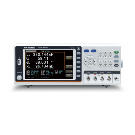
LCR-8000 Series User Manual Appearance Front Panel This key is used to turn the device Power instrument on/off. For executing the function indicated Function for the position corresponding to the Function key. Soft keys for use to select corresponding option which located on the right of the LCD screen. - Page 17 GETTING STARTED For control the Bias unit and for DC BIAS executing on/off. The key will be locked to prevent from Key Lock controlling the push key and the computer by both sides. To use the keypad again, press this key again. Press this button to return the cursor to the top left corner of the currently displayed page or cancel current...
-
Page 18: Rear Panel
LCR-8000 Series User Manual Rear Panel Trigger input port TRIGGER USB port (Type B) This port is used for remote control. Power Socket: Power Cord Socket AC 100~240V, 50/60Hz, 65VA max LAN port GPIB port GPIB RS-232 port RS232 Handler I/O port Handler I/O... -
Page 19: Set Up
GETTING STARTED Set Up Tilting the Stand Lifting the instrument, starting from the front stand. Horizontal position Tilt stand position Carry position... -
Page 20: Power Up
LCR-8000 Series User Manual Power UP 1. Insert the AC power cord into the power Steps socket. 2. Press the power button to turn the LCR-8200 series on. 3. The power button will Press down and the LCR-8200 series will start to boot up. -
Page 21: Connect To The Test Terminal
GETTING STARTED Connect to the test terminal Please use the test fixture to connect to the test Background terminal for testing. Please follow the procedure below to connect. Please insert the test fixture into the terminal of Steps the test equipment correctly. 1. - Page 22 LCR-8000 Series User Manual Avoid wrong connection, which would lead to Note incorrect reading value. In order to ensure the accuracy of the instrument, please use the LCR-8200 optional accessories test cable for test. Before connecting the test leads, make sure the Warning test leads are not connected to any component to avoid personal injury or damage to the...
-
Page 23: Measure (Meter Mode)
MEASURE (METER MODE) EASURE (METER MODE) In this chapter you will learn about all the measurement-related settings. All the measurement setting items can be found on the [MEAS DISPLAY] [MEASURE MODE SETUP] page. Measure display area description ........24 Setting parameter .............. 25 Setting frequency............... -
Page 24: Measure Display Area Description
LCR-8000 Series User Manual Measure display area description The measurement display is a Meter mode that provides a single condition for numerical measurements. SWEEP Sweep mode page. Provides the Available measurement value to graphic parameter curve function. LIST SET List setting page. LIST RUN List run test page. -
Page 25: Setting Parameter
MEASURE (METER MODE) Setting parameter 1. Press the Measure button to enter Steps [MEAS DISPLAY] page. 2. Use arrow keys to move the cursor and select Parameter 1~4 item on the [MEAS DISPLAY] page. 3. Use option key on the right of the LCD screen to select a parameter for this measurement item. - Page 26 LCR-8000 Series User Manual Resistance Reactance Absolute value of admittance Conductivity Susceptance Up to four component parameters can be selected Note in the meter mode. The inductance and DCR values can be measured and displayed simultaneously.
-
Page 27: Setting Frequency
MEASURE (METER MODE) Setting frequency The frequency range is 10Hz~5MHz/10MHz/20MHz/30MHz, and the resolution is set at 6 digits.. 1. Press the Measure button to enter Steps [MEAS DISPLAY] page. 2. Use arrow keys to move cursor and select FREQ item on the [MEAS DISPLAY] page. - Page 28 LCR-8000 Series User Manual Decrease the second digit of the frequency value Decrease the first digit of the frequency value...
-
Page 29: Setting Speed
MEASURE (METER MODE) Setting speed LCR-8200 Series offers 5 test speeds (SLOW2, SLOW, MED., FAST and MAX.). The slower the test, the more accurate and stable the test result. 1. Press the Measure button to enter Steps [MEAS DISPLAY] page. 2. -
Page 30: Setting Trigger Mode
LCR-8000 Series User Manual Setting trigger mode LCR-8200 Series offers REPEAT and SINGLE mode. 1. Press the Setup button to enter [MEAS Steps SETUP] page. 2. Use arrow keys to move cursor and select TRIGGER item on the [MEAS SETUP] page. - Page 31 MEASURE (METER MODE) Manual mode: The device performs a measurement once the Trigger button is pressed. Handler mode: When a negative edge pulse is received from the handler interface on the rear panel, the device performs a measurement cycle. TRIGGER Input mode: When a ...
-
Page 32: Setting Measurement Level/Alc/Ro
LCR-8000 Series User Manual Setting measurement level/ALC/RO LCR-8200 Series test signal voltage/current level can be set as the effective value (RMS value) of a sine wave of the test frequency from the unit’s internal oscillator. The voltage range is 10mV- 2Vrms and current range is 100uA-20mArms. - Page 33 MEASURE (METER MODE) 1. Press the Measure button to enter [MEAS Steps DISPLAY] page. 2. Use arrow keys to move cursor and select LEVEL item on the [MEAS DISPLAY] page. 3. Use option key on the right of the LCD screen to adjust the level value or use the numeric keypad to enter the test level and select ALC/RO for this measurement item.
-
Page 34: Setting Dc Bias
LCR-8000 Series User Manual Setting DC bias LCR-8200 Series offers DC BIAS ±12V. When input is above the instrument voltage range will be displayed “Out of range!”. Steps Press the Measure button to enter [MEAS DISPLAY] page. 2. Use arrow keys to move cursor and select BIAS item on the [MEAS DISPLAY] page. - Page 35 MEASURE (METER MODE) Increase 1V of the DC Bias value Available parameter Increase 0.1V of the DC Bias value Decrease 0.1V of the DC Bias value Decrease 1V of the DC Bias value ...
-
Page 36: Setting Measurement Ac Range
LCR-8000 Series User Manual Setting measurement AC range The range recommendation is set to [Auto] for better measurement accuracy. The actual measured range will be displayed in the lower left corner of the screen. When set to [HOLD], faster measurement speeds can be achieved. However, when the range is selected incorrectly, it will result in inaccurate or incorrect values. -
Page 37: Setting Measurement Dc Range
MEASURE (METER MODE) Setting measurement DC range The range recommendation is set to [Auto] for better measurement accuracy. The actual measured range will be displayed in the lower center of the screen. When set to [HOLD], faster measurement speeds can be achieved. However, when the range is selected incorrectly, it will result in inaccurate or incorrect values. -
Page 38: Setting Trigger Delay Timer
LCR-8000 Series User Manual Setting trigger delay timer LCR-8200 Series can set the delay time before each test by setting trigger delay timer. The delay time range is 0ms~5000ms. 1. Press the Setup button to enter Steps [MEASURE MODE SETUP] page. 2. -
Page 39: Setting Ac/Dc Delay Timer
MEASURE (METER MODE) Setting AC/DC delay timer LCR-8200 Series can set the AC/DC delay time when Rdc parameter enable . The inductance and Rdc values can be measured and displayed simultaneously. When the inductance is measured by Rdc, a current flows through the generated magnetic field. -
Page 40: Setting Average Count
LCR-8000 Series User Manual Setting average count This function is to perform multiple measurements and take an average result from multiple measurements as the final display value. The stability and reliability of the measurement results can be improved by utilizing this function. The number of measurements can be set from 1 to 64. -
Page 41: Setting Display Vm/Im Mode
MEASURE (METER MODE) Setting display Vm/Im mode The test signal voltage and test signal current of the AC and the test signal voltage and test signal current of the DC on the test object. Turn on the Vm/Im display to help understand the setting status of ALC and RO. -
Page 42: Setting Beep Mode
LCR-8000 Series User Manual Setting beep mode When the comparison function setting is turned on, the value judgment result will be indicated by color, and the buzzer function can be set to use the sound to know the measurement result. 1. -
Page 43: Setting Statistics Mode
MEASURE (METER MODE) Setting statistics mode When the comparison function setting is on, the statistics function can be turned on to calculate the measurement quantity of PASS and FAIL. 1. Press the Setup button to enter Steps [MEASURE MODE SETUP] page. 2. -
Page 44: Setting Comparator
LCR-8000 Series User Manual Setting comparator In this section, user will learn how to set up comparator and bin sorting. The device can perform comparator function for 1~4 parameter simultaneously or separately. Choose to set the bin condition for each parameter, which can be divided into 2~9 classes. Bin methods include equalization, sequence, tolerance and random;... - Page 45 MEASURE (METER MODE) 4. Use arrow keys to select COMP Set up comp MODE. mode VALUE The measured values are compared. Available options Select this mode, the NOMINAL field does not need to be set, just set the UPPER and LOWER upper and lower limits.
- Page 46 LCR-8000 Series User Manual △ The difference between the measured value and the NOMINAL value is compared. Absolute value (Δ) = measure value – nominal value Select this mode, the NOMINAL value and UPPER and LOWER upper and lower limits must be set. △% The difference between the measured value and the NOMINAL value is...
- Page 47 MEASURE (METER MODE) 1. Use arrow keys to move cursor and Set up select NOMINAL or UPPER and nominal/upper/lo LOWER. 2. Use key pad to input value and unit. NOMINAL Compare nominal values. Set only Available options in the △ and △% modes. UPPER Comparison of upper limit LOWER...
- Page 48 LCR-8000 Series User Manual △ Display the difference between the measured value and the NOMINAL value △% Display the difference between the measured value and the NOMINAL value is compared with the percentage of the NOMINAL value. 4. Press the Measure button to enter Comparator [MEAS DISPLAY] page.
- Page 49 MEASURE (METER MODE) 6. Press the Measure button to enter Comparator [MEAS DISPLAY] page. Comparator result display result is Pass in green color or Fail in red color.
-
Page 50: Setting Bin Sorting
LCR-8000 Series User Manual Setting bin sorting Choose to set the bin condition for each parameter, which can be divided into 2~9 classes. Bin methods include equalization, sequence, tolerance and random; limit value modes include measured values, tolerance values, and tolerance %. 1. - Page 51 MEASURE (METER MODE) Set up parameter 3. Use arrow keys to select PARAMETER item. 4. Use option key on the right of the LCD screen to select a desired item. The MEAS DISPLAY has selected parameters to have display options. Turn off the bin function.
- Page 52 LCR-8000 Series User Manual 7. Use arrow keys to move cursor and Set up bin select BIN NUMBER item. number 8. Use key pad to input bin number value.(2~9) 9. Use arrow keys to move cursor and Set up bin select BIN METHOD item.
- Page 53 MEASURE (METER MODE) Equal Sort by equally average. Set the Available options high/low value. Sequential Sort by order. Set each value. Tolerance Sort by order. Set each value. Random Sort by user. Set each range value.
- Page 54 LCR-8000 Series User Manual Set up limit mode 11. Use arrow keys to move cursor and select LIMIT MODE. 12. Use option key on the right of the LCD screen to select a desired item. VALUE The measured values are compared. Available options Select this mode, the NOMINAL field does not need to be set, just set the...
- Page 55 MEASURE (METER MODE) △ The difference between the measured value and the NOMINAL value is compared. Absolute value (Δ) = measure value – nominal value Select this mode, the NOMINAL value and UPPER and LOWER upper and lower limits must be set. △% The difference between the measured value and the NOMINAL value is...
-
Page 56: Setting File
LCR-8000 Series User Manual Setting FILE The parameter can be saved in the flash Memory of the instrument. The meter mode allows the user to access 99 setup groups. 1. Press the Measure button to enter Steps [MEASURE DISPLAY] page. 2. - Page 57 MEASURE (METER MODE) load the files in the temporary files RECALL Available parameter for testing Open an empty file and setting the file name Save the test file in the RAM to SAVE AS another file. Delete the file, the file which is DELETE being used (red) cannot delete.
-
Page 58: Setting Usb Disk
LCR-8000 Series User Manual Setting USB disk USB disk can store test setup files and LCD screen images and SWEEP measurement curves and magnitude data. Available types and file formats: USB disk type: Flash disk only. Format: FAT32 / exFAT. Max memory size: 128GB. - Page 59 MEASURE (METER MODE) Save screen Save LCD screen images to USB disk. Available options Path> USB:\LCR8200\SCREEN\SCNxxxx.BMP File USB file management. management Path> USB:\LCR8200\METER Format USB Format the USB disk(FAT32) drive...
-
Page 60: Sweep (Graph Mode)
LCR-8000 Series User Manual WEEP (GRAPH MODE) In this chapter you will learn about all the sweep- related settings. All the sweep items can be found on the [SWEEP DISPLAY] [SWEEP MODE SETUP] page. Sweep display area description ........61 Setting type ............... -
Page 61: Sweep Display Area Description
SWEEP (GRAPH MODE) Sweep display area description The sweep display is a sweep graph mode that provides a sweep range condition for graph measurements. Available Measure meter mode page. MEASURE parameter LIST SET List setting page. LIST RUN List run test page. CORR. -
Page 62: Setting Type
LCR-8000 Series User Manual Setting type Sweep type has 3 kinds, which are frequency, Vac and Iac, respectively. 1. Press the Measure button to enter Steps [MEAS DISPLAY] page, and then press the SWEEP function button on the right side of the LCD to enter the [SWEEP DISPLAY] page. -
Page 63: Setting X-Axis
SWEEP (GRAPH MODE) Setting X-axis The X-axis scale shows 2 modes LINEAR and LOG. 1. Press the Measure button to enter Steps [MEAS DISPLAY] page, and then press the SWEEP function button on the right side of the LCD to enter the [SWEEP DISPLAY] page. -
Page 64: Setting Start
LCR-8000 Series User Manual Setting start Sweep test condition start value. (frequency, Vac, Iac) 1. Press the Measure button to enter Steps [MEAS DISPLAY] page, and then press the SWEEP function button on the right side of the LCD to enter the [SWEEP DISPLAY] page. -
Page 65: Setting Stop
SWEEP (GRAPH MODE) Setting stop Sweep test condition stop value. (frequency, Vac, Iac) 1. Press the Measure button to enter Steps [MEAS DISPLAY] page, and then press the SWEEP function button on the right side of the LCD to enter the [SWEEP DISPLAY] page. -
Page 66: Setting Level/Freq
LCR-8000 Series User Manual Setting level/freq When performing a frequency sweep test, you need to set the test voltage/current (Vac/Iac). If you are performing a voltage/current scan test, you need to set the test frequency. The voltage range is 10mV-2Vrms and current range is 0.1mA-20mArms. 2Vrms can only be used at <= 1MHz. -
Page 67: Setting Bias
SWEEP (GRAPH MODE) Setting bias LCR-8200 Series offers DC BIAS ±12V. BIAS has a set value, when the trigger test starts, DC BIAS will automatically turn on the output, and the DC BIAS button indicator will light up; at the end of the test, DC BIAS will automatically turn off and the light will be off. -
Page 68: Setting Trig
LCR-8000 Series User Manual Setting trig Trig mode has REPEAT and SINGLE mode. Press the Trigger button to start the sweep test once. 1. Press the Measure button to enter Steps [MEAS DISPLAY] page, and then press the SWEEP function button on the right side of the LCD to enter the [SWEEP DISPLAY] page. - Page 69 SWEEP (GRAPH MODE) sweep test once the Trigger button is pressed. Handler mode: When a negative edge pulse is received from the handler interface on the rear panel, the device performs a sweep test cycle. TRIGGER Input mode: When a ...
-
Page 70: Setting Speed
LCR-8000 Series User Manual Setting speed 3 test speeds ( SLOW, MED., FAST). The slower the test, the more accurate and stable the test result. 1. Press the Measure button to enter Steps [MEAS DISPLAY] page, and then press the SWEEP function button on the right side of the LCD to enter the [SWEEP DISPLAY] page. -
Page 71: Setting Scale
SWEEP (GRAPH MODE) Setting scale The scale of the Y-axis is displayed with the setting of trace A or trace B. 1. Press the Measure button to enter Steps [MEAS DISPLAY] page, and then press the SWEEP function button on the right side of the LCD to enter the [SWEEP DISPLAY] page. -
Page 72: Setting Func
LCR-8000 Series User Manual Setting func Select the combination of parameters to be sweep test. Func1-16: Z-Deg, Y-Deg, R-X, G-B, Z-Cs, Z-Cp, Z-Ls, Z-Lp, Cs-Rs, Cp-Rp, Cp-G, Cs-D, Ls-Rs, Lp-Rp, Lp-G, Ls-Q. FUNC selection If you do not have the desired test parameters, you can go to the PARA item of TRACE A/B and select the required test parameters. -
Page 73: Setting Para
SWEEP (GRAPH MODE) Setting para Select test parameters of trace A or trace B. 1. Press the Measure button to enter Steps [MEAS DISPLAY] page, and then press the SWEEP function button on the right side of the LCD to enter the [SWEEP DISPLAY] page. -
Page 74: Setting Y-Axis
LCR-8000 Series User Manual Setting Y-axis The Y-axis scale shows 2 modes LINEAR and LOG of trace A or trace B. 1. Press the Measure button to enter Steps [MEAS DISPLAY] page, and then press the SWEEP function button on the right side of the LCD to enter the [SWEEP DISPLAY] page. -
Page 75: Setting Ref
SWEEP (GRAPH MODE) Setting ref Set the Y-axis reference point scale for trace A or B. This parameter can be set by selecting LINEAR in Y-axis. 1. Press the Measure button to enter Steps [MEAS DISPLAY] page, and then press the SWEEP function button on the right side of the LCD to enter the [SWEEP DISPLAY] page. -
Page 76: Setting Pos
LCR-8000 Series User Manual Setting pos Move the graphic of trace A or trace B. 1. Press the Measure button to enter Steps [MEAS DISPLAY] page, and then press the SWEEP function button on the right side of the LCD to enter the [SWEEP DISPLAY] page. -
Page 77: Setting Div/Decade
SWEEP (GRAPH MODE) Setting div/decade The scale of the Y-axis is displayed with the setting of trace A or trace B. 1. Press the Measure button to enter Steps [MEAS DISPLAY] page, and then press the SWEEP function button on the right side of the LCD to enter the [SWEEP DISPLAY] page. -
Page 78: Setting Sweep Delay
LCR-8000 Series User Manual Setting sweep delay Set the sweep test the delay time between each test point and point. The delay time range is 0ms~5000ms. 1. Press the Measure button to enter Steps [MEAS DISPLAY] page, and then press the SWEEP function button on the right side of the LCD to enter the [SWEEP DISPLAY] page, and press the Setup button to enter [SWEEP... -
Page 79: Setting Output Impedance
SWEEP (GRAPH MODE) Setting output impedance The output impedance can be set to 25Ω or 100Ω. The varied signal source output impedance will lead to the varied current or the difference of measuring value. If selecting <25Ω>, then the voltage range is 10mV~1Vrms and the current range is 400µA~40mArms. -
Page 80: Setting Keep Previous Trace
LCR-8000 Series User Manual Setting keep previous trace Save sweep graph for part alignment or adjustment. 1. Press the Measure button to enter Steps [MEAS DISPLAY] page, and then press the SWEEP function button on the right side of the LCD to enter the [SWEEP DISPLAY] page, and press the Setup button to enter [SWEEP MODE SETUP] page. - Page 81 SWEEP (GRAPH MODE) Save sweep graph turn off Available parameter Save sweep graph turn on Multiple parts are compared to the measurement Function Description curve, this function can be turned on, and the parts are measured in order to understand the difference.
-
Page 82: Setting Trace A/B Color
LCR-8000 Series User Manual Setting trace A/B color Set the display color of trace A or trace B. 1. Press the Measure button to enter Steps [MEAS DISPLAY] page, and then press the SWEEP function button on the right side of the LCD to enter the [SWEEP DISPLAY] page, and press the Setup button to enter [SWEEP MODE SETUP] page. -
Page 83: Setting Usb Disk
SWEEP (GRAPH MODE) Setting USB disk USB disk can store test setup files and LCD screen images and SWEEP measurement curves and magnitude data. Available types and file formats: USB disk type: Flash disk only. Format: FAT32 / exFAT. Max memory size: 128GB. 1. - Page 84 LCR-8000 Series User Manual Save screen Save LCD screen images to USB disk. Available options Path> USB:\LCR8200\SCREEN\SCNxxxx.B Save sweep Save sweep graph to USB disk. graphic Path> USB:\LCR8200\SWEEP\SWPxxxx.BMP Save sweep Save sweep measure data to USB disk. data Path> USB:\LCR8200\SWEEP\SWPxxxx.CSV Format USB Format the USB disk(FAT32) drive...
-
Page 85: List (Multi Step Mode)
LIST (MULTI STEP MODE) IST (MULTI STEP MODE) In this chapter you will learn about all the list- related settings. All the list setting items can be found on the[LIST SET] [LIST MODE SETUP] [LIST RUN] page. LIST SET/LIST RUN display area description ....86 Setting step ............... -
Page 86: [List Run] Page
LCR-8000 Series User Manual LIST SET/LIST RUN display area description The list measurement display is a multi-step mode that provides simultaneous multi-condition measurement for the part. Meter mode page MEASURE Available parameter Sweep mode page. SWEEP List run test page LIST RUN Correction page CORR. -
Page 87: Setting Step
LIST (MULTI STEP MODE) Setting step LIST SET has 15 steps to set. 1. Press the Measure button to enter Steps [MEAS DISPLAY] page, and then press the LIST SET function button on the right side of the LCD to enter the [LIST SET] page. - Page 88 LCR-8000 Series User Manual Copy the cursor where the step is COPY Available added to the next step. parameter Copy setp1 to setp2. Insert a blank step in the cursor step to INSERT the next step. Insert blank step in the next step of step1.
-
Page 89: Setting Parameter
LIST (MULTI STEP MODE) Setting parameter 1. Press the Measure button to enter Steps [MEAS DISPLAY] page, and then press the LIST SET function button on the right side of the LCD to enter the [LIST SET] page. 2. Use arrow keys to move cursor and select PARAMETER item on the [LIST SET] page. - Page 90 LCR-8000 Series User Manual θ Phase angle of impedance(radian) Quality Factor, (Q = 1/D) Dissipation Factor , Loss coefficient (tanδ) Resistance Reactance Absolute value of admittance Conductivity Susceptance...
-
Page 91: Setting Frequency
LIST (MULTI STEP MODE) Setting frequency The frequency range is 10Hz~5MHz/10MHz/20MHz/30MHz, and the resolution is set at 6 digits.. 1. Press the Measure button to enter Steps [MEAS DISPLAY] page, and then press the LIST SET function button on the right side of the LCD to enter the [LIST SET] page. -
Page 92: Setting Level
LCR-8000 Series User Manual Setting level Test signal voltage/current level can be set (RMS value). The voltage range is 10mV-2Vrms and current range is 0.1mA- 20mArms. 2Vrms can only be used at <= 1MHz.. 1. Press the Measure button to enter Steps [MEAS DISPLAY] page, and then press the LIST SET function button... -
Page 93: Setting Dc Bias
LIST (MULTI STEP MODE) Setting DC bias DC BIAS range is -12V~+12V. When input is above the instrument voltage range will be displayed “Out of range!”. The test step has DC BIAS. When this step is tested, the instrument will automatically execute the DC BIAS output, and the DC Bias button will light up and will automatically turn off at the end of the step. -
Page 94: Setting Speed
LCR-8000 Series User Manual Setting speed 5 test speeds (SLOW2, SLOW, MED., FAST and MAX.). The slower the test, the more accurate and stable the test result. 1. Press the Measure button to enter Steps [MEAS DISPLAY] page, and then press the LIST SET function button on the right side of the LCD to enter the [LIST SET] page. -
Page 95: Setting Delay
LIST (MULTI STEP MODE) Setting delay Set the delay time before each test step. The delay time range is 0ms~5000ms. 1. Press the Measure button to enter Steps [MEAS DISPLAY] page, and then press the LIST SET function button on the right side of the LCD to enter the [LIST SET] page. -
Page 96: Setting Comp Mode
LCR-8000 Series User Manual Setting comp mode The comparison function settings of 1 to 15 steps can be performed separately. The comparison mode has measured values, tolerance values and tolerance %. 1. Press the Measure button to enter Steps [MEAS DISPLAY] page, and then press the LIST SET function button on the right side of the LCD to enter the [LIST SET] page. - Page 97 LIST (MULTI STEP MODE) VALUE The measured values are compared. Available options Select this mode, the NOMINAL field does not need to be set, just set the UPPER and LOWER upper and lower limits. △ The difference between the measured value and the NOMINAL value is compared.
- Page 98 LCR-8000 Series User Manual △% The difference between the measured value and the NOMINAL value is compared with the percentage of the NOMINAL value. Deviation percentages (Δ%) = Absolute value (Δ)/nominal value × 100% Select this mode, the NOMINAL value and UPPER and LOWER upper and lower limits must be set.
- Page 99 LIST (MULTI STEP MODE) UPPER Comparison of upper limit LOWER Comparison of lower limit 6. Press the LIST RUN function button on Comparator the right side of the LCD to enter [LIST result display RUN] page and press the Trigger button to run test.
-
Page 100: Setting Trigger Mode
LCR-8000 Series User Manual Setting trigger mode List test step offers REPEAT and SINGLE and AUTO mode. When the part is tested manually, it is traditionally necessary to connect the object to be tested, and then press the TRIGGER button or use the foot switch to start the measurement. - Page 101 LIST (MULTI STEP MODE) REPEAT The repeat trigger mode is an internal Available continuous test. Press the Trigger parameter button to start all the steps of the LIST test, and repeat all the steps until the STOP function button on the right side of the LCD is pressed.
- Page 102 LCR-8000 Series User Manual Off" Reduce the waiting trigger time, with FAIL RETEST setting, suitable for manual testing. The mode status is displayed in the middle of the LCD.
-
Page 103: Setting Trigger Delay
LIST (MULTI STEP MODE) Setting trigger delay Set the trigger delay time before each list test. The delay time range is 0ms~5000ms. 1. Press the Measure button to enter Steps [MEAS DISPLAY] page, and press the LIST SET function button on the right side of the LCD to enter the [LIST SET] page, and then press the Setup button to enter [LIST MODE SETUP]... -
Page 104: Setting Output Impedance
LCR-8000 Series User Manual Setting OUTPUT IMPEDANCE The output impedance can be set to 25Ω or 100Ω. The varied signal source output impedance will lead to the varied current or the difference of measuring value. If selecting <25Ω>, then the voltage range is 10mV~1Vrms and the current range is 400µA~40mArms. -
Page 105: Setting Alc
LIST (MULTI STEP MODE) Setting ALC The ALC (automatic level control) feature adjusts the voltage across the DUT or the current through the DUT to match the voltage/current level setting. Using this feature, you can try to ensure a constant signal level (voltage or current) is applied to the DUT. -
Page 106: Setting Beep When
LCR-8000 Series User Manual Setting beep when When the comparison function setting is turned on, the value judgment result will be indicated by color, and the buzzer function can be set to use the sound to know the list test result. 1. -
Page 107: Setting Range Hold
LIST (MULTI STEP MODE) Setting range hold When RANGE HOLD is set to OFF, the instrument will use the automatic range to measure to get the correct amount. When RANGE HOLD is set to ON, use the correct part for the first measurement. -
Page 108: Setting Fail Reset
LCR-8000 Series User Manual Setting fail reset Using the AUTO mode for part testing saves time and accuracy, but sometimes the measurement results are wrong due to poor contact! You can use the FAIL RETEST function to re-measure when the contact is poor, so as to avoid the problem. -
Page 109: Setting Statistics
LIST (MULTI STEP MODE) Setting statistics When the comparison function setting is on, the statistics function can be turned on to calculate the measurement quantity of PASS and FAIL. 1. Press the Measure button to enter Steps [MEAS DISPLAY] page, and press the LIST SET function button on the right side of the LCD to enter the [LIST SET] page, and then press the Setup... -
Page 110: Setting Bin Sorting
LCR-8000 Series User Manual Setting bin sorting Choose to set the bin condition for each parameter, which can be divided into 2~9 classes. Bin methods include equalization, sequence, tolerance and random; limit value modes include measured values, tolerance values, and tolerance %. 1. - Page 111 LIST (MULTI STEP MODE) Set up parameter 4. Use arrow keys to select PARAMETER item. 5. Use the SELECT option button on the right side of the LCD screen. Select the steps you want to perform the sorting. 6. Use arrow keys to move cursor and Set up bin select BIN NUMBER item.
- Page 112 LCR-8000 Series User Manual 8. Use arrow keys to move cursor and Set up bin select BIN METHOD item. method 9. Use option key on the right of the LCD screen to select a desired item. Equal Sort by equally average. Set the Available options high/low value.
- Page 113 LIST (MULTI STEP MODE) Tolerance Sort by order. Set each value. Random Sort by user. Set each range value. 10. Use arrow keys to move cursor and Set up limit select LIMIT MODE. mode 11. Use option key on the right of the LCD screen to select a desired item.
- Page 114 LCR-8000 Series User Manual VALUE The measured values are compared. Available options Select this mode, the NOMINAL field does not need to be set, just set the UPPER and LOWER upper and lower limits. △ The difference between the measured value and the NOMINAL value is compared.
- Page 115 LIST (MULTI STEP MODE) △% The difference between the measured value and the NOMINAL value is compared with the percentage of the NOMINAL value. Deviation percentages (Δ%) = Absolute value (Δ)/nominal value × 100% Select this mode, the NOMINAL value and UPPER and LOWER upper and lower limits must be set.
-
Page 116: Setting File
LCR-8000 Series User Manual Setting FILE The list setup can be saved in the flash Memory of the instrument. The list mode allows the user to access 48 setup groups. 1. Press the Measure button to enter Steps [MEAS DISPLAY] page, and then press the LIST SET function button on the right side of the LCD to enter the [LIST SET] page. - Page 117 LIST (MULTI STEP MODE) load the files in the temporary files RECALL Available parameter for testing Open an empty file and setting the file name Save the test file in the RAM to SAVE AS another file. Delete the file, the file which is DELETE being used (red) cannot delete.
-
Page 118: Setting Usb Disk
LCR-8000 Series User Manual Setting USB disk USB disk can store list setup files and LCD screen images. Available types and file formats: USB disk type: Flash disk only. Format: FAT32 / exFAT. Max memory size: 128GB. 1. Insert a USB disk for using as data Steps recoding. - Page 119 LIST (MULTI STEP MODE) Save screen Save LCD screen images to USB disk. Available options Path> USB:\LCR8200\SCREEN\SCNxxxx.B File USB file management. management Path> USB:\LCR8200\LIST Format USB Format the USB disk(FAT32) drive...
-
Page 120: Correction (Open/Short)
LCR-8000 Series User Manual ORRECTION (OPEN/SHORT) In this chapter you will learn about all the correction settings. Correction process ............121 Setting open ..............123 Setting short ..............125 Setting HF load ............... 127 Setting spot load ............. 129 Setting cable length ............131 Setting fixture compensation.......... -
Page 121: Correction Process
CORRECTION (OPEN/SHORT) Correction process Prior to each measurement, the user needs to correction the fixture or test cable to eliminate stray capacitance and series impedance that may be generated by the fixture or test cable. Application when using LCR-8200 or changing a fixture in a new environment. Please check the test unit and the test fixture used for correct correction. - Page 122 LCR-8000 Series User Manual The HF LOAD correction is not necessarily Note performed. Please refer to the test fixture using the operating manual and correct it according to the conditions. 7. Connect the STD-LOAD to the test fixture, and then perform HF LOAD correction. The SPOT LOAD correction is not necessarily Note performed.
-
Page 123: Setting Open
CORRECTION (OPEN/SHORT) Setting open For normal measurements, it is recommended that this item be executed. OPEN correction capability cancels errors due to the stray admittance in the test fixture. 1. Press the Measure button to enter Steps [MEAS DISPLAY] page, and then press the CORR. - Page 124 LCR-8000 Series User Manual The open correction is quite sensitive to noise - Note both noise originating externally and induced noise. Therefore, if open correction fails, you should check the following points before starting the correction process again: Check that the test fixture or the test cables are properly connected.
-
Page 125: Setting Short
CORRECTION (OPEN/SHORT) Setting short For normal measurements, it is recommended that this item be executed. The short correction compensates for any residual impedances, such as the impedance of the cables and the DUT connection points. 1. Press the Measure button to enter Steps [MEAS DISPLAY] page, and then press the CORR. - Page 126 LCR-8000 Series User Manual If short correction fails, you should check the Note following points before starting the correction process again: Check that the test fixture or the test cables are properly connected. Check that the test fixture or the test cables are properly shorted together with the shorting bar.
-
Page 127: Setting Hf Load
CORRECTION (OPEN/SHORT) Setting HF load This item does not necessarily need to be implemented. Some test fixtures have a standard LOAD, which can be performed with reference to the fixture instructions and requirements to perform LOAD (PHASE) compensation. 1. Press the Measure button to enter Steps [MEAS DISPLAY] page, and then press the CORR. - Page 128 LCR-8000 Series User Manual If HF load correction fails, you should check the Note following points before starting the correction process again: Check that the test fixture or the test cables are properly connected. Check that the test fixture or the test cables are properly shorted together with the STD- LOAD.
-
Page 129: Setting Spot Load
CORRECTION (OPEN/SHORT) Setting spot load This item does not necessarily need to be implemented. If the OPEN/SHOR/LOAD compensation cannot make the measurement correct, you can perform SPOT LOAD compensation to let the instrument know the correct value through learning. Use the part with the known value as the standard value which will be recognized by the instrument during the test, the instrument will then shows this value in the test status. - Page 130 LCR-8000 Series User Manual If SPOT LOAD correction fails, you should check Note the following points before starting the correction process again: Check that the test fixture or the test cables are properly connected. Check that the test fixture or the test cables are properly shorted together with the part.
-
Page 131: Setting Cable Length
CORRECTION (OPEN/SHORT) Setting cable length When using a wired test fixture, set the length according to the line length to compensate when OPEN/SHOT correction. 1. Press the Measure button to enter Steps [MEAS DISPLAY] page, and then press the CORR. function button on the right side of the LCD to enter the [CORRECTION] page. -
Page 132: Setting Fixture Compensation
LCR-8000 Series User Manual Setting fixture compensation If use a dedicated test fixture, select the corresponding option to do OPEN/SHORT/LOAD correction, which can increase the measurement accuracy. 1. Press the Measure button to enter Steps [MEAS DISPLAY] page, and then press the CORR. -
Page 133: Setting Spot No
CORRECTION (OPEN/SHORT) Setting spot no. The SPOT LOAD compensation point can be set to a maximum of 16 points. If the test frequency and measurement parameters are not the same, you need to increase the SPOT set point. 1. Press the Measure button to enter Steps [MEAS DISPLAY] page, and then press the CORR. -
Page 134: Setting Frequency
LCR-8000 Series User Manual Setting frequency Set whether each SPOT LOAD point is turned on. To use it, set the measurement frequency. 1. Press the Measure button to enter Steps [MEAS DISPLAY] page, and then press the CORR. function button on the right side of the LCD to enter the [CORRECTION] page. -
Page 135: Setting Load Function
CORRECTION (OPEN/SHORT) Setting load function SPOT LOAD needs to set the real and imaginary values of the test part measurement parameters to obtain the correct phase angle and other calculation data. 1. Press the Measure button to enter Steps [MEAS DISPLAY] page, and then press the CORR. - Page 136 LCR-8000 Series User Manual Load function: <G-B>、<R-X>、<Cp-Rp>、<Cp- Note D>、<Cs-Rs>、<Cs-D>、<Lp-Rp>、<Lp-Q>、 <Ls-Rs>、<Ls-Q>、<Y-Deg>、<Z-Deg> Impedance is defined as, where the real part of impedance is the resistance R and the imaginary part is the reactance X...
-
Page 137: Setting Reference
CORRECTION (OPEN/SHORT) Setting reference Input the real part and imaginary part value with the part . 1. Press the Measure button to enter Steps [MEAS DISPLAY] page, and then press the CORR. function button on the right side of the LCD to enter the [CORRECTION] page. -
Page 138: Measure Load
LCR-8000 Series User Manual Measure load The short correction compensates for any residual impedances, such as the impedance of the cables and the DUT connection points. 1. Press the Measure button to enter Steps [MEAS DISPLAY] page, and then press the CORR. function button on the right side of the LCD to enter the [CORRECTION] page. -
Page 139: System Configuration
SYSTEM CONFIGURATION YSTEM CONFIGURATION In this section, user will learn how to set the parameters on SYSTEM CONFIG page. Setting GPIB address ............140 Setting RS232 BAUD RATE ..........141 Setting RS232 EOI ............142 Setting LAN PORT ............143 Setting HANDLER INTERFACE ........ -
Page 140: Setting Gpib Address
LCR-8000 Series User Manual Setting GPIB address Set up the GPIB port address 1-30. 1. Press System button at the top right of Steps the LCD screen to enter the [SYSTEM CONFIG] setting page. 2. Use up and down arrow keys to select GPIB ADDRESS on this setting page. -
Page 141: Setting Rs232 Baud Rate
SYSTEM CONFIGURATION Setting RS232 BAUD RATE Set the RS-232 port baud rate. The USB port is the same baud rate used in VCP mode. 1. Press System button at the top right of Steps the LCD screen to enter the [SYSTEM CONFIG] setting page. -
Page 142: Setting Rs232 Eoi
LCR-8000 Series User Manual Setting RS232 EOI Set RS-232 command and return value the end of identify (EOI). 1. Press System button at the top right of Steps the LCD screen to enter the [SYSTEM CONFIG] setting page. 2. Use up and down arrow keys to select RS232 BAUD RATE on this setting page. -
Page 143: Setting Lan Port
SYSTEM CONFIGURATION Setting LAN PORT Set LAN port setting. 1. Press System button at the top right of Steps the LCD screen to enter the [SYSTEM CONFIG] setting page. 2. Use up and down arrow keys to select LAN SETUP on this setting page. 3. - Page 144 LCR-8000 Series User Manual AUTO Automatically obtains the IP address Available parameter MANUAL Manually configures the IP address RESTART Reset the Ethernet card when new settings have been ready AUTO setting 5. The network line is inserted into the LAN port behind the machine, and the instrument reads the IP settings by automatically.
-
Page 145: Setting Handler Interface
SYSTEM CONFIGURATION Setting HANDLER INTERFACE Set the handle interface to open and close state. Requires Handler I/O output, need to enable setting. Without I/O output, the interface circuit can be closed, which can save measurement processing time about 1-2ms. 1. Press System button at the top right of Steps the LCD screen to enter the [SYSTEM CONFIG] setting page. -
Page 146: Setting Key Beep
LCR-8000 Series User Manual Setting KEY BEEP Set the response sound when the keypad is operated 1. Press System button at the top right of the Steps LCD screen to enter the [SYSTEM CONFIG] setting page. 2. Use up and down arrow keys to select KEY BEEP on this setting page. -
Page 147: Remote Control
REMOTE CONTROL EMOTE CONTROL This chapter describes basic configuration of remote control. Handler Overview ............148 Terminal type..............148 Terminal diagrams ............149 Universal terminal ............150 Meter mode (BIN off) terminal ........151 List mode (BIN off) terminal .......... 151 Meter/List mode (BIN on) terminal ....... -
Page 148: Handler Overview
LCR-8000 Series User Manual Handler Overview The device provides a full-featured handler interface that includes output signals of OK/NG and EOM, input signals of TRIG (activated by external trigger). Through this interface, the device can be easily controlled with the control components of user's system to complete automatic control functions. -
Page 149: Terminal Diagrams
REMOTE CONTROL Terminal diagrams... -
Page 150: Universal Terminal
LCR-8000 Series User Manual Universal terminal Pin# Name Logic Description Negative, External trigger signal, pulse /EXT_TRIG I Edge width ≥ 100μs Negative, ‘’End of all measurement’’ /EOM Level signal Negative, /PASS Level Pass signal of comparator Negative, /FAIL Fail signal of comparator Level Signal Trig Return... -
Page 151: Meter Mode (Bin Off) Terminal
REMOTE CONTROL Meter mode (BIN off) terminal Pin# Name Logic Description Negative, /PARA-1OK O Comparator result Level Negative, Comparator result /PARA-2OK O Level Negative, /PARA-3OK O Comparator result Level Negative, /PARA-4OK O Comparator result Level Negative, Comparator result /PARA-1NG O Level Negative, /PARA-2NG O... -
Page 152: Meter/List Mode (Bin On) Terminal
LCR-8000 Series User Manual Level Negative, Comparator result /STEP-2NG O Level Negative, Comparator result /STEP-3NG O Level Negative, Comparator result /STEP-4NG O Level Meter/List mode (BIN on) terminal Pin# Name Logic Description Negative, Bin judgment result /BIN1 Level Negative, Bin judgment result /BIN2 Level Negative,... -
Page 153: Electrical Parameters
REMOTE CONTROL Electrical parameters Please set the Handler Interface ON in SYSTEM menu to enable remote control and set the dip switch to on (both switches are pulling down). The internal power output is 5V and 100mA at maximum. - Page 154 LCR-8000 Series User Manual Connection method for input circuit Input signal: effective in Negative, Edge Note PIN1 (trigger) + PIN5 (gnd) Start testing after short circuit, the shorting time must be greater than 100uS.
- Page 155 REMOTE CONTROL Connection method for output circuit Output signal: effective in Negative, Level Maximum voltage: 30VDC Note Maximum current: 30mA The other output pins are photo coupler circuit, output signal is low level. The output is as a high resistance floating circuit when it without action.
-
Page 156: Timing Chart
LCR-8000 Series User Manual To avoid damaging the interface, the voltage of power supply voltage can’t exceed the power Note requirements. To avoid damaging the interface, please connect cable after the device is powered off. Timing Chart... -
Page 157: Configure Interface
REMOTE CONTROL Configure Interface The device uses the GPIB/ LAN/ RS-232/ USB Overview interface to communicate with the computer to complete all devices’ functions. With standard SCPI commands, users can easily create various acquisition systems which are suitable for themselves. GPIB Interface The computer and the measuring instrument are connected with GPIB (General-Purpose Interface Bus) cable, and the Test Piece will... -
Page 158: Configure Gpib Interface
LCR-8000 Series User Manual Configure GPIB Interface 24-pin block GPIB Pin Assignments Pin Definition Pin Definition Dataline1 Dataline5 Dataline2 Dataline6 Dataline3 Dataline7 Dataline4 Dataline8 Ground NRFD Ground NDAC Ground Ground Ground Ground Shield Signal ground LAN Interface 10/100 Base T Ethernet, 8 pins The instrument will be connected to the LAN (Local Area Network) ports. -
Page 159: Rs-232C Interface
REMOTE CONTROL RS-232C Interface The RS-232 serial interface can be connected to the serial interface of a controller (PC or IPC) through a DB9 cable. Use a GWINSTEK (null modem) DB-9 cable. Cable length should not exceed 2 meters. Note ... -
Page 160: Usb Interface
LCR-8000 Series User Manual USB Interface The device is equipped with built-in USB-232 interface which can directly virtualize the USB port as an RS232 port in the computer. This virtual port can perform the same functions as RS232 and use the same settings as the RS232 port. -
Page 161: Install Usb Driver
REMOTE CONTROL Install USB Driver The USB driver needs to be installed when using Background the USB port for remote control. The USB interface creates a virtual COM port when connected to a Install the USB VCP Driver (zadig-2.4.exe) from lnstall the USB the CD. - Page 162 LCR-8000 Series User Manual The Zadig software will detect the LCR-8200, select CDC, and press “Install Driver” to install the driver. Successful installation. The LCR-8200 and the COM port that it is assigned to will now appear under the Ports (COM &...
-
Page 163: External Trigger Input
REMOTE CONTROL Please use the CD comes with the device to install. Click on the directory: USB VCP Drive Note To avoid electrical shock, turn off the power when plugging and unplugging the DB9 cable. If the driver installation is completed correctly, ... -
Page 164: Command Overview
LCR-8000 Series User Manual OMMAND OVERVIEW The Command overview chapter lists all programming commands in functional order as well as alphabetical order. The command syntax section shows you the basic syntax rules you have to apply when using commands. Command Syntax ............165 Command error code ............. -
Page 165: Command Syntax
COMMAND OVERVIEW Command Syntax IEEE488.2 Partial compatibility Compatible Standard SCPI, 1994 Partial compatibility SCPI (Standard Commands for Programmable Command Instruments) commands follow a tree-like Structure structure, organized into nodes. Each level of the command tree is a node. Each keyword in a SCPI command represents each node in the command tree. - Page 166 LCR-8000 Series User Manual Query A query is a simple or compound command followed by a question mark (?). A parameter (data) is returned. Example :INPut:CFACtor? Commands and queries have two different Command Forms forms, long and short. The command syntax is written with the short form of the command in capitals and the remainder (long form) in lower case.
- Page 167 COMMAND OVERVIEW Command header Parameter 1 Space Type Description Example Common Input Parameters <Boolean> Boolean logic 0, 1 <NR1> integers 0, 1, 2, 3 <NR2> decimal numbers 0.1, 3.14, 8.5 <NR3> floating point with 4.5e-1, 8.25e+1 exponent <NRf> any of NR1, 2, 3 1, 1.5, 4.5e-1 [MIN] For commands, this will set the setting...
-
Page 168: Command Error Code
LCR-8000 Series User Manual Command error code -100 // Command error -102 // Syntax error -108 // Parameter not allow (Too much parameters) -109 // Missing parameter -113 // Undefined header (query a command only command or query command missing '?') -121 // Invalid character in number -128 // Numeric data not allowed -131 // Invalid suffix... -
Page 169: Command List
COMMAND OVERVIEW Command List Command :STATus:OPERation:CONDition? ............176 :STATus:OPERation:EVENt? ..............176 :STATus:OPERation:ENABle <NR1> ............ 176 :STATus:OPERation:ENABle? ............... 176 :STATus:QUEStionable:CONDition? ............ 176 :STATus:QUEStionable:EVENt? ............177 :STATus:QUEStionable:ENABle <NR1> ..........177 :STATus:QUEStionable:ENABle? ............177 *CLS ....................... 177 *ESE <NR1> ..................177 *ESE? ..................... 177 *ESR? ..................... -
Page 170: Commands
LCR-8000 Series User Manual Measure Subsystem :MEASure:PARAmeter {OFF|RDC|LS|LP|CS|CP|Q|D|RS|RP|Z|DEG|RAD|R|X|Y|G|B|E|U} ..181 :MEASure:PARAmeter? ................. 181 : MEASure : FREQuency < frequency NR3/disc> ........181 :MEASure:FREQuency? ................. 181 :MEASure:SPEEd {MAXimum|FAST|MEDium|SLOW|SLOW2|0|1|2|3|4}182 :MEASure:SPEEd?.................. 182 :MEASure:BEEPer {OFF|PASS|OK|FAIL|NG|0|1|2] ....... 182 :MEASure:BEEPer? ................182 :MEASure:VOLTage:AC <voltage NR3/disc> ........182 :MEASure:VOLTage:AC? ............... - Page 171 COMMAND OVERVIEW :MEASure:COMParator:MODE <ABSolute|DEViation|PERCent|0|1|2>188 :MEASure:COMParator:NOMinal <nominal value NR3> ....188 :MEASure:COMParator:NOMinal? ............188 :MEASure:COMParator:UPPER <upper limit NR3> ......189 :MEASure:COMParator:UPPER? ............189 :MEASure:COMParator:LOWER <LOWER limit NR3> ......189 :MEASure:COMParator:DISPlay <ABSolute|DEViation|PERCent|0|1|2>189 :MEASure:COMParator:DISPlay? ............189 :MEASure:BIN:PARAmeter {OFF|RDC|LS|LP|CS|CP|Q|D|RS|RP|Z|DEG|RAD|R|X|Y|G|B|E|U} ..190 :MEASure:BIN:PARAmeter? ..............190 :MEASure:BIN:NUMBer {2|3|4|5|6|7|8|9|MAXium|MINimum}...
- Page 172 LCR-8000 Series User Manual List Subsystem :LIST:STEP{1|2|3|4|…|14|15} ..............195 :LIST:STEP? .................... 195 :LIST:PARAmeter {OFF|RDC|LS|LP|CS|CP|Q|D|RS|RP|Z|DEG|RAD|R|X|Y|G|B} ....195 :LIST:PARAmeter? ................. 195 :LIST:FREQuency <frequencyNR3/disc> ..........195 :LIST:FREQuency? ................. 195 :LIST:VOLTage<voltage NR3/disc > ............. 196 :LIST:VOLTage? ..................196 :LIST:CURRent <current NR3/disc > ............ 196 :LIST:CURRent? ..................
- Page 173 COMMAND OVERVIEW :LIST:TRIGger:DELay <delay time NR3/disc> ........201 :LIST:TRIGger:DELay? ................201 :LIST:OIMPedance {100|25} ..............202 :LIST:OIMPedance? ................202 :LIST:ALC {OFF|ON|0|1} ............... 202 :LIST:BEEPer {OFF|PASS|OK|FAIL|NG|0|1|2] ........202 :LIST:BEEPer? ..................202 :LIST:RANGe {AUTO|HOLD|0|1} ............202 :LIST:RANGe? ..................202 :LIST:RETest {OFF|STEP|ALL|0|1|2} ............. 203 :LIST:RETest? ..................
- Page 174 LCR-8000 Series User Manual Sweep Subsystem :SWEep:TYPE {FREQuency|VAC|IAC} ........... 206 :SWEep:TYPE? ..................206 :SWEep:XAXis {LOGarithm|LINear} ............. 206 :SWEep:XAXis? ..................206 :SWEep:XAXis:DATA? ................206 :SWEep:STARt <startNR3/disc> ............207 :SWEep:STARt? ..................207 :SWEep:STOP <stopNR3/disc> ............207 :SWEep:STOP?..................207 : SWEep:FREQuency <frequencyNR3/disc> ........... 208 :SWEep:FREQuency? ................
- Page 175 COMMAND OVERVIEW :SWEep:TRACA:YAXis {LOGarithm|LINear} ........213 :SWEep:TRACA:YAXis? ................213 :SWEep:TRACA:REFerence <value NR3> ..........213 :SWEep:TRACA:REFerence? ..............213 :SWEep:TRACA:POSition {-10 ~ 16|MAXimun|MINimum} ....214 :SWEep:TRACA:POSition? ..............214 :SWEep:TRACA:DIVision <value NR3/disc> ........214 :SWEep:TRACA:DIVision? ..............214 :SWEep:TRACA:DECade {1~12} ............214 :SWEep:TRACA:DECade? ..............214 :SWEep:TRACA:MAXimun? ..............
-
Page 176: Status:operation:condition
LCR-8000 Series User Manual Commands :STATus:OPERation:CONDition? Function: It queries the status of Operation Status Register. Description: Return data 0~65535 (Format is in <NR1>) :STATus:OPERation:EVENt? Function: It queries the status of Operation Event Register. Description: Return data 0~65535 (Format is in <NR1>) :STATus:OPERation:ENABle <NR1>... -
Page 177: Status:questionable:event
COMMAND OVERVIEW :STATus:QUEStionable:EVENt? Function: It queries the status of Questionable Event Register. Description: Return data 0~65535 (Format is in <NR1>) :STATus:QUEStionable:ENABle <NR1> :STATus:QUEStionable:ENABle? Function: It sets or queries the status Questionable Enable Register. Description: Set parameter 0~65535 <NR1> Set syntax :STATus:QUEStionable:ENABle 65535 Query syntax :STATus:QUEStionable:ENABle? Return data 0~65535 (Format is in <NR1>) *CLS... -
Page 178: Esr
LCR-8000 Series User Manual *ESR? Function: It queries the status of Standard Event Status Register, clean the Register after executed. Description: Return data <NR1> *IDN? Function: It queries the identification of the instrument. Description: Return data <field1>,<field2>,<field3>,<field4> <field1>manufacturer <field2>model number <field3>serial number or 0 <field4>firmware revision *OPC... -
Page 179: Rst
COMMAND OVERVIEW *RST Function: It aborts all pending operations, and sets 8230 to meter mode with initial setups. Description: Initial Setups Parameters:Ls,Q,Z,θdeg FREQuency:1kHz LEVEL:1Vac SPEED:MED. TRIGger:REPEAT *SRE <NR1> *SRE? Function: It sets or queries the status of Service Request Enable Register. -
Page 180: Tst
LCR-8000 Series User Manual *TST Function:The response to this query is always 0. *TRG *TRG? :TRIGger :TRIGger? Function:It executes Trigger action. If using *TRG? and :TRIGger, it executes Trigger action and returms test data. :DISPlay:PAGE{MEASure|SWEep|CORRection|LSET|LRUN|LCOR Rection|SYSTem} :DISPlay:PAGE? Function: It sets or queries the page currently displayed on the LCD screen. -
Page 181: Measure Subsystem
COMMAND OVERVIEW MEASure Subsystem :MEASure:PARAmeter {OFF|RDC|LS|LP|CS|CP|Q|D|RS|RP|Z|DEG|RAD|R|X|Y|G|B|E|U} :MEASure:PARAmeter? Function: It sets or queries the measurement parameter (max.4 items) at present. Description: Set parameter OFF, RDC(DC Resistance), Ls(Series Inductance), Lp(Parallel Inductance), Cs (Series Capacitance), Cp (Parallel Capacitance), Q (Quality Factor), D (Dissipation Factor), Rs (Series Resistance) Rp(Parallel Resistance), Z(Impedance), θd(Angle), θr(Diameter), R(Resistance), X(Reactance), Y (Admittance), G (Conductivity), B (Susceptance). -
Page 182: Measure:speed
LCR-8000 Series User Manual :MEASure:FREQuency MINimum Query syntax :MEASure:FREQuency? Return data 1.000000E+03 (Format is in <NR3>) :MEASure:SPEEd {MAXimum|FAST|MEDium|SLOW|SLOW2|0|1|2|3|4} :MEASure:SPEEd? Function: It sets or queries the SPEED. Description: Set parameter MAXimum/0, FAST/1, MEDium/2, SLOW/3,SLOW2/4 Set syntax :MEASure:SPEEd 1 :MEASure:SPEEd FAST Query syntax :MEASure:SPEEd? Return data FAST (Format is in <disc>) :MEASure:BEEPer {OFF|PASS|OK|FAIL|NG|0|1|2] :MEASure:BEEPer? -
Page 183: Measure:current:ac
COMMAND OVERVIEW RO (output impedance) is setting 25Ω, the setup value of AC voltage is {0.01~1|MAXimum|MINimum}. Set syntax :MEASure:VOLTage:AC 1 :MEASure:VOLTage:AC 1M :MEASure:VOLTage:AC 1MV :MEASure:VOLTage:AC 1E-3 :MEASure:VOLTage:AC MAXimum :MEASure:VOLTage:AC MINimum Query syntax :MEASure:VOLTage:AC? Return data 1.000000E+00 (Format is in <NR3>) When the Level setup is current mode, the data returns 9.9E37. -
Page 184: Measure:alc {Off|On|0|1
LCR-8000 Series User Manual :MEASure:ALC {OFF|ON|0|1} :MEASure:ALC? Function: It sets or queries the ALC. Description: Query syntax :MEASure: ALC? Return data When the setup is OFF, it returns 0. When the setup is ON, it returns 1. :MEASure:SMONitor {0|1|OFF |ON} :MEASure:SMONitor? Function:... -
Page 185: Measure:average
COMMAND OVERVIEW :MEASure:AVERage <average NR1> :MEASure:AVERage? Function: It sets or queries the AVERAGE. Description: Set parameter The value of the Average is {0~64} Set syntax :MEASure:AVERageage 10 Query syntax :MEASure:AVERageage? Return data 10 (Format is in <NR1>) :MEASure:FONT {SMALl|LARGe} :MEASure:FONT? Function:... -
Page 186: Measure:delay
LCR-8000 Series User Manual :MEASure:DELay <delay time NR3/disc> :MEASure:DELay? Function: It sets or queries the AC/DC DELAY. Description: Set parameter The value of delay time i s { 0.0~5|MAXimum|MINimum}. Set syntax :MEASure:DELay 0.5 :MEASure:DELay 500M :MEASure:DELay 500MS :MEASure:DELay 5E-3 :MEASure:DELay MAXimum :MEASure:DELayMINimum Query syntax :MEASure:DELay? Return data 0.500 (Format is in <NR2>) -
Page 187: Measure:range:ac {1|2|3|4|Auto|Hold
COMMAND OVERVIEW :MEASure:RANGe:AC {1|2|3|4|AUTO|HOLD} Function: It sets or queries the AC RANGE. Description: Set parameter {1|2|3|4| AUTO | HOLD } Set syntax :MEASure:RANGe:AC 3 :MEASure:RANGe:AC AUTO Query syntax :MEASure:RANGe:AC Return data 3 (Format is in <NR1>) :MEASure:OIMPedance {100|25} :MEASure:OIMPedance? Function: It sets or queries the RO. Description:... -
Page 188: Measure:comparator:state {Off|On|0|1
LCR-8000 Series User Manual :MEASure:COMParator:STATe {OFF|ON|0|1} :MEASure:COMParator:STATe? Function: It sets or queries the COMP enabled/disabled. Description:: MEASure:COMParator:STATe? Return data When the setup is OFF, it returns 0. When the setup is ON, it returns 1. :MEASure:COMParator:MODE <ABSolute|DEViation|PERCent|0|1|2> Function: It sets or queries the COMP MODE. Description:... -
Page 189: Measure:comparator:upper
COMMAND OVERVIEW :MEASure:COMParator:UPPER <upper limit NR3> :MEASure:COMParator:UPPER? Function: It sets or queries the UPPER. Description: Set syntax :MEASure:COMParator:UPPER 1 :MEASure:COMParator:UPPER1000M :MEASure:COMParator:UPPER 1E+00 Query syntax :MEASure:COMParator:UPPER? Return data 1.000000E+00 (Format is in <NR3>) :MEASure:COMParator:LOWER <LOWER limit NR3> Function: It sets or queries the LOWER. Description:... -
Page 190: Measure:bin:parameter
LCR-8000 Series User Manual :MEASure:BIN:PARAmeter {OFF|RDC|LS|LP|CS|CP|Q|D|RS|RP|Z|DEG|RAD|R|X|Y|G|B|E|U} :MEASure:BIN:PARAmeter? Function: It sets or queries the BIN Parameter. Description: Set syntax :MEASure:BIN:PARAmeter Z(only allow the parameter which is being used under the meter mode.) Query syntax :MEASure:PARAmeter? Return data Z(Format is in <disc>) :MEASure:BIN:NUMBer {2|3|4|5|6|7|8|9|MAXium|MINimum} :MEASure:BIN:NUMBer? Function:... -
Page 191: Measure:bin:mode
COMMAND OVERVIEW :MEASure:BIN:MODE <ABSolute|DEViation|PERCent|0|1|2> :MEASure:BIN:MODE? Function: It sets or queries the BIN MODE. Description: Set parameter ABSolute,0|DEViation,1|PERCent,2 Set syntax :MEASure:BIN:MODE DEViation Query syntax :MEASure:BIN:MODE:MODE? Return data DEV(Format is in <disc>) :MEASure:BIN:NOMinal <nominal value NR3 > :MEASure:BIN:NOMinal? Function: It sets or queries the BIN NOMINAL. Description:... -
Page 192: Measure:fil E:load
LCR-8000 Series User Manual :MEASure:FIL E:LOAD ? Function: It queries the meter mode's filename which is being using. Description: Query syntax :MEASure:FILE:LOAD ? Return data ABC :FETCh? Function: Read the measured value Description: Query syntax FETC? Return data Meter Mode Read Data format under Meter Mode <para 1 data>,<para 2 data>,<para 3 data>,<para 4 data>,<status>,<bin number>,<para 1 compare... -
Page 193: Correction:open
COMMAND OVERVIEW be displayed when the bin function is disabled. -1 – bin out, not in the categorization number 1 ~ 9 – bin number, the categorization result is 1~9. para compare status 1-4 Measuring comparison result: If any parameter comparison function is enabled, then the comparison result will be displayed for all of the parameters. -
Page 194: Correction:short
LCR-8000 Series User Manual :CORRection:SHORt :CORRection:SHORt? Function: It sets or queries to do short correction. Description: Query syntax :CORRection:SHORt? Return data When correction fail, it returns 0. When correction passes, it returns 1. :CORRection:OPEN:STATe {OFF|ON|0|1} :CORRection:OPEN:STATe? Function: It sets or queries the status of open correction. Description:... -
Page 195: List Subsystem
COMMAND OVERVIEW LIST Subsystem :LIST:STEP{1|2|3|4|…|14|15} :LIST:STEP? Function: It sets or queries the step to edit. Description: Set parameter step number1~15 Set syntax :LIST:STEP 1 Query syntax :LIST:STEP? Return data 1(Format is in <NR1>) :LIST:PARAmeter {OFF|RDC|LS|LP|CS|CP|Q|D|RS|RP|Z|DEG|RAD|R|X|Y|G|B} :LIST:PARAmeter? Function: It sets or queries the measurement parameter of list mode. -
Page 196: List:voltage
LCR-8000 Series User Manual :LIST:FREQuency 1KHZ :LIST:FREQuency 1E3 :LIST:FREQuency MAXimum :LIST:FREQuencyMINimum Query syntax :LIST:FREQuency? Return data 1.000000E+03(Format is in <NR3) :LIST:VOLTage<voltage NR3/disc > :LIST:VOLTage? Function: It sets or queries the measurement voltage of list mode. Description: Set parameter When RO(output impedance) is 100Ω, the setup range of AC voltage is {0.01~2|MAXimum|MINimum}. -
Page 197: List:speed {Maximum|Fast|Medium|Slow|Slow2|0|1|2|3|4
COMMAND OVERVIEW current is {0.0002~0.04|MAXimum|MINimum}. The range of DC current is {0.0002~0.04|MAXimum|MINimum}. Set syntax :LIST:CURRent 1 :LIST:CURRent 1M :LIST:CURRent 1MA :LIST:CURRent 1E-3 :LIST:CURRent MAXimum :LIST:CURRentMINimum Query syntax :LIST:CURRent? Return data 1.000000E+00 (Format is in <NR3>) When the Level setup is current mode, the data returns 9.9E37. :LIST:SPEEd {MAXimum|FAST|MEDium|SLOW|SLOW2|0|1|2|3|4} :LIST:SPEEd? Function:... -
Page 198: List:comparator:mode
LCR-8000 Series User Manual :LIST:DELayMINimum Query syntax :LIST:DELay? Return data 0.500 (Format is in <NR2>) :LIST:COMParator:MODE <ABSolute|DEViation|PERCent|0|1|2> Function: It sets or queries the COMP MODE of list mode. Description: Set parameter ABSolute,0|DEViation,1|PERCent,2 Set syntax :MEASure:COMParator:MODE PERCent Query syntax :LIST:COMParator:MODE? Return data PERC (Format is in <disc>) :LIST:COMParator:NOMinal <nominal value NR3 >... -
Page 199: List:comparator:lower
COMMAND OVERVIEW :LIST:COMParator:LOWER <LOWER limit NR3> :LIST:COMParator:LOWER? Function: It sets or queries the LOWER of list mode. Description: Set syntax :LIST:COMParator: LOWER -1 :LIST:COMParator: LOWER -1000M :LIST:COMParator: LOWER -1E+00 Query syntax :LIST:COMParator: LOWER ? Return data -1.000000E+00 (Format is in <NR3>) :LIST:BIN:PARAmeter {OFF|RDC|LS|LP|CS|CP|Q|D|RS|RP|Z|DEG|RAD|R|X|Y|G|B|} :LIST:BIN:PARAmeter? -
Page 200: List:bin:method
LCR-8000 Series User Manual :LIST:BIN:METHod {EQUal|SEQuential|TOLerance|RANDom|0|1|2|3} :LIST:BIN:METHod? Function: It sets or queries the BIN METHOD of list mode. Description: Set parameter EQUal,0| SEQuential,1|TOLerance,2 |RANDom,3 Set syntax :LIST:BIN:METHod SEQ Query syntax :LIST:BIN:METHod? Return data SEQ (Format is in <disc>) :LIST:BIN:MODE <ABSolute|DEViation|PERCent|0|1|2> :LIST:BIN:MODE? Function:... -
Page 201: List:bin:limit
COMMAND OVERVIEW :LIST:BIN:LIMit <nominal value NR3 > :LIST:BIN:LIMit? Function: It sets or queries the BIN LIMIT of list mode. Description: Set syntax :LIST:BIN :BIN:LIMit 0.001,100M,1k,1000k Query syntax :LIST:BIN:BIN:LIMit? Return data +1.000000E-03, +1.000000E-01, +1.000000E+03, +1.000000E+06 (Format is in <NR3>) :LIST:TRIGger:MODE {REPeat|SINGle|AUTO} :LIST:TRIGger:MODE? Function:... -
Page 202: List:oimpedance {100|25
LCR-8000 Series User Manual :LIST:OIMPedance {100|25} :LIST:OIMPedance? Function: It sets or queries the RO of list mode. Description: Query syntax :LIST:OIMPedance? Return data 100|25 (Format is in <NR1>) :LIST:ALC {OFF|ON|0|1} Function: It sets or queries the ALC of list mode. Description:... -
Page 203: List:retest {Off|Step|All|0|1|2
COMMAND OVERVIEW the most suitable test range is set automatically. Set syntax :LIST:RANGe AUTO :LIST:RANGe 1 Query syntax :LIST:RANGe? Return data AUTO |HOLD (Format is in <disc>) :LIST:RETest {OFF|STEP|ALL|0|1|2} :LIST:RETest? Function: It sets or queries the FAIL RETEST of list mode. Description:... -
Page 204: Lcorrection:short
LCR-8000 Series User Manual Query syntax : LCORrection:OPEN? Return data When correction fail, it returns 0. When correction passes, it returns 1. :LCORrection:SHORt :LCORrection:SHORt? Function: It sets or queries to do the short correction of list mode. Description: Query syntax :LCORrection:SHORt? Return data When correction fail, it returns 0. -
Page 205: Lcorrection:cable {0|0.75|1|2
COMMAND OVERVIEW :LCORrection:CABLe {0|0.75|1|2} :LCORrection:CABLe? Function: It sets or queries the status of cable length correction. Description: Query syntax :LCORrection:CABLe? Return data 0|0.75|1|2 :LIST:FILE:LOAD <filename> Function: It loads the list file. Description: Set syntax :MEASure:FILE:LOAD ABC.(Load the file “ABC”) :LIST:FILE:LOAD? Function:... -
Page 206: Sweep Subsystem
LCR-8000 Series User Manual SWEep Subsystem :SWEep:TYPE {FREQuency|VAC|IAC} :SWEep:TYPE? Function: It sets or queries the sweep type. Description: Set parameter FREQuency | VAC(voltage) |IAC(current) Set syntax :SWEep:TYPE FREQuency Query syntax :LIST:RETest? Return data FREQ | VAC | IAC (Format is in <disc>) :SWEep:XAXis {LOGarithm|LINear} :SWEep:XAXis? Function:... -
Page 207: Sweep:start
COMMAND OVERVIEW :SWEep:STARt <startNR3/disc> :SWEep:STARt? Function: It sets or queries the START. Description: Set parameter The start value of frequency is {10.0~30000000.0|MAXimum|MINimum}. The start value of voltage AC RO 100Ω is {0.01~2|MAXimum|MINimum}. The start value of voltage AC RO 25Ω is {0.01~1|MAXimum|MINimum}. -
Page 208: Sweep:frequency
LCR-8000 Series User Manual { 0.0002~0.02 |MAXimum|MINimum}. The stop value of current AC RO 25Ω is { 0.0002~0.04 |MAXimum|MINimum}. Set syntax :SWEep:STARt 0.5 :SWEep:STARt 500M :SWEep:STARt 5E-3 :SWEep:STARt MAXimum :SWEep:STARt MINimum Query syntax :SWEep:STARt? Return data +5.000000E-01(Format is in <NR3>) : SWEep:FREQuency <frequencyNR3/disc>... -
Page 209: Sweep:voltage
COMMAND OVERVIEW :SWEep:VOLTage <voltage NR3/disc> :SWEep:VOLTage? Function: It sets or queries the LEVEL to voltage mode, when the TYPE setup is FREQ. Description: Set parameter The value of voltage AC RO 100Ω is {0.01~2|MAXimum|MINimum}. The value of voltage AC RO 25Ω is {0.01~1|MAXimum|MINimum}. -
Page 210: Sweep:trigger:mode
LCR-8000 Series User Manual :SWEep:CURRent MAXimum :SWEep:CURRentMINimum Query syntax :SWEep:CURRent? Return data 1.000000E+03(Format is in <NR3>) When the LEVEL setup is not current mode, the data returns 9.9E37. : SWEep:TRIGger:MODE <REPeat|SINGle|0|1> :SWEep:TRIGger:MODE? Function: It sets or queries the sweep trigger mode. Description:... -
Page 211: Sweep:trace {A|B
COMMAND OVERVIEW :SWEep:TRACe {A|B} :SWEep:TRACe? Function: It sets or queries which trace is in use. Description: Set syntax :SWEep:TRACe A Querysyntax :SWEep:TRACe? Return data A | B (Format is in <disc>) :SWEep:FUNCtion {LS|LP|CS|CP|Q|D|RS|RP|Z|DEG|RAD|R|X|Y|G|B,OFF|LS|LP|CS|CP |Q|D|RS|RP|Z|DEG|RAD|R|X|Y|G|B } :SWEep:FUNCtion? Function: It sets or queries the sweep function. Description :... -
Page 212: Sweep:delay
LCR-8000 Series User Manual :SWEep:DELay <delay timeNR3/disc> :SWEep:DELay? Function: It sets or queries the sweep delay between measurement points. Description: Set parameter The value of delay time is {0.0~5|MAXimum|MINimum}. Set syntax :SWEep:DELay 0.5 :SWEep:DELay 500M :SWEep:DELay 500MS :SWEep:DELay 5E-3 :SWEep:DELay MAXimum :SWEep:DELayMINimum Query syntax :SWEep:DELay? Return data 0.500 (Format is in <NR2>) -
Page 213: Sweep:traca:parameter
COMMAND OVERVIEW :SWEep:TRACA:PARAmeter {LS|LP|CS|CP|Q|D|RS|RP|Z|DEG|RAD|R|X|Y|G|B|} :SWEep:TRACA:PARAmeter? Function: It sets or queries the parameter of TRACE A Description : Set parameter The first parameter cannot be set to OFF. Set syntax :SWEep:TRACA:PARAmeter Z Query syntax :SWEep:TRACA:PARAmeter? Return data Z(Format is in <disc>) :SWEep:TRACA:YAXis {LOGarithm|LINear} :SWEep:TRACA:YAXis? Function:... -
Page 214: Sweep:traca:position {-10 ~ 16|Maximun|Minimum
LCR-8000 Series User Manual :SWEep:TRACA:POSition {-10 ~ 16|MAXimun|MINimum} :SWEep:TRACA:POSition? Function: It sets or queries the position of TRACE A. Description: Set parameter {-10 ~ 16|MAXimun|MINimum} Set syntax :SWEep:TRACA:POSition -3 Query syntax :SWEep:TRACA:POSition? Return data -3 (Format is in <NR1>) :SWEep:TRACA:DIVision <value NR3/disc> :SWEep:TRACA:DIVision? Function:... -
Page 215: Sweep:traca:maximun
COMMAND OVERVIEW :SWEep:TRACA:MAXimun? Function: It queries the maximum of TRACE A. Description: Query syntax : SWEep:TRACA:MAXimun? Return data +2.230924E+06,+3.221517E-03. :SWEep:TRACA:MINimum? Function: It queries the minimum of TRACE A. Description: Query syntax :SWEep:TRACA:MINimum? Return data +2.310130E+06,-3.446227E-03 (Format is in <NR3>). :SWEep:TRACA:RESult? Function:... -
Page 216: Sweep:tracb:yaxis {Logarithm|Linear
LCR-8000 Series User Manual :SWEep:TRACB:YAXis {LOGarithm|LINear} :SWEep:TRACB:YAXis? Function: It sets or queries the Y-AXIS of TRACE A. Description: Set parameter LOGarithm | LINear Set syntax :SWEep:TRACB:YAXis LOGarithm Query syntax :SWEep:TRACB:YAXis? Return data LOG | LIN (Format is in <disc>) :SWEep:TRACB:REFerence <value NR3> :SWEep:TRACB:REFerence? Function:... -
Page 217: Sweep:tracb:division
COMMAND OVERVIEW :SWEep:TRACB:DIVision <value NR3/disc> :SWEep:TRACB:DIVision? Function: It sets or queries the DIV of TRACE B. Description: Set parameter The numeric value can only be set to 1, 2, 5 and 10(when Y-axis setup is linear mode). Set syntax :SWEep:TRACB:DIVision 2k Query syntax :SWEep:TRACB:DIVision? Return data 2.000000E+03 (Format is in <NR3>) :SWEep:TRACB:DECade {1~12}... -
Page 218: Sweep:tracb:minimum
LCR-8000 Series User Manual :SWEep:TRACB:MINimum? Function: It queries the minimum of TRACE B and corresponding frequency | voltage | current. Description: Query syntax :SWEep:TRACB:MINimum? Return data +2.310130E+06,-3.446227E-03 (Format is in <NR3>).The first data is the corresponding frequency | voltage | current. -
Page 219: Sweep:analysis:result
COMMAND OVERVIEW :SWEep:ANALysis:RESult? Function: It queries all of the value data and corresponding frequency | voltage | current of TRACE A and TRACE B. Description: Query syntax :SWEep:ANALysis:RESult? Return data +1.000000E+03 , +2.212126E-04 , +1.398695E+00 , +1.035500E+03 , +2.209532E-04 , +1.446218E+00…(Format is in <NR3>). -
Page 220: Appendix
LCR-8000 Series User Manual PPENDIX Preset ................221 Specifications ..............223 General Specifications ............ 223 Specifications ..............224 Dimensions ..............230 Declaration of Conformity ..........231 Measurement Basics ............. 232 Resistance (R) and Conductance (G) ......233 Capacitance (C) ............... 235 Inductance (L) .............. -
Page 221: Preset
APPENDIX Preset The following are the default settings for the RESET on the Meter/Sweep/List setup page. METER MODE (Applicable to create a new meter file) MEAS DISPLAY Default Setting Parameter 1 Parameter 2 Parameter 3 Parameter 4 Frequency 1.0kHz Level/RO/ALC 1V/100Ω/OFF Speed TRIGER MODE... - Page 222 LCR-8000 Series User Manual FUNCTION Z-Deg TRACE A PARAMETER Y-AXIS LOG. REFERENCE POSITION +2 DECADE DECADE TRACE B PARAMETER Y-AXIS LINEAR REFERENCE POSITION DIVISION 20Deg SWEEP MODE SETUP Default Setting SWEEP DELAY 100Ω KEEP PREVIOUS TRACE TRACE A COLOR YELLOW TRACE B COLOR GREEN LIST MODE (Applicable to create a new meter file)
-
Page 223: Specifications
APPENDIX Specifications Below are the basic conditions required to operate the LCR-8200 series within specifications. Calibration: Yearly Reset adjustment: Perform correction before testing The specifications Apply when it warmed up for at least 60 minutes. General Specifications Specification Conditions: Temperature: 18˚C~28˚C Humidity:... -
Page 224: Specifications
LCR-8000 Series User Manual Average 1 to 64 V/I Monitor Vac, Iac, Vdc, Idc File Storage Meter: 99 sets, List: 48 sets Comparator Value, △, △% Handler PASS, FAIL and OK, NG or BIN 1-9 Buzzer OFF, Pass, Fail Trigger REPEAT, SINGLE Interface USB/GPIB/LAN/RS-232/Handler/USB... - Page 225 APPENDIX ± 0.00000 μS to 999.999kS G, B ± 0.000 ° to180.000° θ ± 0.00000 to 3.14159 θ ± 0.000 % to 999.999% Δ% 0.00mΩ to 99.9999MΩ Voltage Signal Level *f: Measure frequency [MHz] 10mV ~ 2Vrms (f≦ 1 MHz) Range 10mV ~ 1Vrms (f>...
- Page 226 LCR-8000 Series User Manual Signal Level DC 1V, 40mA max Accuracy ±1% Output Impedance 25Ω (nominal) DC Bias Range 0 to ± 12 V Resolution 1 mV Accuracy ±(0.3% ± 2mV) Measurement Speed Max: 2.5ms (>10kHz) Fast: 50ms (>20Hz) Medium: 100ms Slow: 300ms...
- Page 227 APPENDIX Accuracy Conditions of accuracy: All specifications apply at 23 ± 5 °C, and 60 minutes after the instrument has been turned on. Impedance measurement accuracy at 4-terminal test fixture (Typical at > 10 MHz) |Z| basic accuracy Chart...
- Page 228 LCR-8000 Series User Manual Ae accuracy If the test conditions are not normal standard, additional calculations are required. Ae = ±( Ab + Az + Av + Ad × Kc × Kt [%] Measurement Frequency:.………………………..…….F[Hz], Fm[MHz] Ab=0.08+(200/F-1) × 0.0222 …………………..……………..(F<200Hz) Ab=0.08 ……………………………………….……...(200Hz≤F≤500kHz) Ab=0.08+(Fm-0.5) x 0.0472 ……………………………….…(F>500kHz) Impedance Range [Ω] :.…………………..…………….F[Hz], Fm[MHz]...
- Page 229 APPENDIX Temperature [°C] Kt=4 ..................(8-18°C) Kt=1+(T-23)² x 0.0139 ..........(18-28°C) Kt=4 ..................(28-38°C) Measure parameter accuracy |Z|, |Y| ±Ae [%], Where Relative accuracy Ae= ±(Ab+Az+Av+Ad) × Kc × Kt [%] θ ±Ae/100 [rad] L, C, X, B ±Ae [%] ……………………………………………………………….(Dx≤0.1) ±Ae×√(1+Dx ) [%]….………………………………………………...(Dx>0.1) ±Ae [%]……………………………………..……………(Dx ≥...
-
Page 230: Dimensions
LCR-8000 Series User Manual Dimensions... -
Page 231: Declaration Of Conformity
APPENDIX Declaration of Conformity GOOD WILL INSTRUMENT CO., LTD. declare that the below mentioned product Type of Product: LCR meter Model Number: LCR-8230/ LCR-8220/ LCR-8210/ LCR-8205 satisfies all the technical relations application to the product within the scope of council: Directive: 2014/30/EU;... -
Page 232: Measurement Basics
LCR-8000 Series User Manual Measurement Basics To measure capacitance, inductance and resistance user can select series or parallel mode. C(Capacitance) : Series mode: Parallel mode: Parallel mode Series mode Equations: Equations: D = dissipation factor D = dissipation factor L(Inductance) : Series mode:... -
Page 233: Resistance (R) And Conductance (G)
APPENDIX R (Resistance) : Series mode: Parallel mode: Parallel mode Series mode Equations: Equations: Q = Quality Factor Q = Quality Factor Resistance (R) and Conductance (G) The resistance is a measure of the difficulty to pass an electric current through that conductor. - Page 234 LCR-8000 Series User Manual Conductance ( G): Measure Type:Parallel mode→ Gp(Conductance is measuring by parallel mode only.) Relevant Equations: ...
-
Page 235: Capacitance (C)
APPENDIX Capacitance (C) Capacitance (denoted by the letter C) is the ability of a body to store an electrical charge at a given potential difference between its plates. The SI unit of capacitance is the farad (symbol: F). Measure Type:Series mode→Cs / Parallel mode→Cp Relevant Equations:... -
Page 236: Inductance (L)
LCR-8000 Series User Manual Inductance (L) Inductance is the property of an electrical conductor by which a change in current through it induces an electromotive force (EMF) in both the conductor itself and in any nearby conductors by mutual inductance. In the SI system, the measurement unit for inductance is the Henry (with the unit symbol H). -
Page 237: Reactance (X) And Susceptance (B)
APPENDIX Reactance (X) and Susceptance (B) In AC circuit analysis, reactance is represented by the capital letter “X” which is the imaginary a part of complex impedance. Reactance is the opposition of a circuit element to a change in the current or voltage, due to that element's inductance or capacitance which is similar to the opposition of resistance to current in a DC circuit. - Page 238 LCR-8000 Series User Manual Susceptance (B): Measure Type:Parallel mode→ Bp (Reactance is measuring by parallel mode only.) Relevant Equations: ...
-
Page 239: Impedance (Z) And Admittance (Y)
APPENDIX Impedance (Z) and Admittance (Y) The impedance covers oppositions in AC circuits including resistance, inductance, and capacitance and is measured in units of Ohm (Ω). In electrical engineering, admittance covers both conductance and susceptance and is the reciprocal of impedance. It is measured in units of Siemens (S). - Page 240 LCR-8000 Series User Manual Admittance (Y): Relevant Equations: ...
-
Page 241: Quality Factor (Q) And Dissipation Factor (D)
APPENDIX Quality factor (Q) and Dissipation factor (D) The quality factor measures energies consumed by relative frequency. In general, the better a circuit's quality factor the better its selectivity. The dissipation factor is the reciprocal of quality factor. It is the signal angle loss by a capacitor (or inductor) and acting frequency at a fixed temperature. - Page 242 LCR-8000 Series User Manual Quality factor (Q): Relevant Equations: series values series values Dissipation factor (D): Relevant Equations: ...
-
Page 243: Phase Angle (Θ)
APPENDIX Phase angle (θ) This is the shift angle when measuring impedance (Z), admittance (Y), quality factor (Q) and dissipation factor (D). Relevant equations:... -
Page 244: Overall Impedance Measurement Theory
LCR-8000 Series User Manual Overall Impedance Measurement Theory The simplified model of the 8230 impedance measurement, Vs is the test signal voltage and RO is source resistance. If the current across the DUT is I when a test signal voltage V is applied, the DUT's impedance, Z, is expressed by Z = . - Page 245 APPENDIX Impedance, Z, can also be expressed as admittance, Y. Admittance is expressed in terms of impedance, Z, by Y = . For parallel connected circuits, it is better to use admittance, Y. G: Conductance B: Susceptance |Y|: Admittance...
- Page 246 LCR-8000 Series User Manual The 8230 measures a DUT's impedance, Z, which is a vector value, and gives the result using the following equivalent circuits.
- Page 247 APPENDIX Lp : Parallel Inductance Cp : Parallel Capacitance Ls : Series Inductance Cs : Series Capacitance Q : Quality factor D : Dissipation factor...
-
Page 248: Characteristics Example
LCR-8000 Series User Manual Characteristics Example As can be seen in the following figure, a component can have different effective parameter values dependent upon its operating condition. The measured values most useful in actual applications are obtained from precise measurement under the actual operating conditions. - Page 249 APPENDIX Lp-G Lp-D Lp-Q Large L Y-∠θ Ls-Rs Ls-D Ls-Q Small L |Z|-∠θ Measurement Characteristics Example Functions Cp-G Large R Y-∠θ Ls-Rs Small R |Z|-∠θ...
-
Page 250: High And Low Impedance Criteria
LCR-8000 Series User Manual High and low impedance criteria The following criteria can be used to roughly discriminate between low, middle, and high impedances by following figure. The medium Z range may be covered with an extension of either the low Z or high Z range.
Need help?
Do you have a question about the LCR Series and is the answer not in the manual?
Questions and answers